
|
Дозатор шприцевой Aitecs 2016 |
||||||
|
||||||
|
||||||
|
||||||
|
||||||
|
||||||
|
||||||
|
||||||
|
||||||
|
||||||
|
||||||
|
||||||
|
||||||
|
||||||
|
||||||
|
||||||
|
||||||
|
||||||
|
||||||
|
||||||
|
||||||
|
||||||
|
||||||
|
||||||
|
||||||
|
||||||
|
||||||
|
||||||
|
||||||
|
||||||
|
||||||
|
||||||
|
||||||
|
||||||
|
||||||
|
||||||
|
||||||
|
||||||
|
||||||
|
||||||
|


 После включения проигрывает контроль как обычно, но вместо картинки установки шприца пишет «Пожалуйста, обратитесь в сервисную службу». И больше никаких кнопок не слушает. В сервисный режим входит. Сервисники сказали, что лекарством служит установка новой даты технического обслуживания, но выход должен быть «плавным», т.е. сначала выйти в начало меню, а уже потом выключать. Пробовал несколько раз (и «плавно» и «резко») — не помогает.
  Loading…

Service Manual
Aitecs 2016
S Y R I N G E I N F U S I O N P U M P
BS049055EN-P01
Prior to servicing this pump, read this manual and the pump’s Operator’s Manual carefully to fully understand the pump’s functionality and to ensure safe and proper servicing.
|
CONTENTS |
|||
|
1. |
INTRODUCTION ………………………………………………………………………………………………………………. |
3 |
|
|
1.1. |
GENERAL INFORMATION ……………………………………………………………………………………….. |
3 |
|
|
1.2. |
GENERAL PRECAUTION………………………………………………………………………………………….. |
3 |
|
|
1.3. |
SERVICE CONTACT …………………………………………………………………………………………………. |
4 |
|
|
2. |
TECHNICAL DESCRIPTION……………………………………………………………………………………………… |
5 |
|
|
2.1. |
GENERAL …………………………………………………………………………………………………………………. |
5 |
|
|
3. |
SERVICE MENU……………………………………………………………………………………………………………….. |
7 |
|
|
3.1. |
MAINTENANCE MENU ……………………………………………………………………………………………. |
7 |
|
|
3.2. |
PROGRAM LOADING……………………………………………………………………………………………….. |
7 |
|
|
3.3. |
MOTOR PROGRAM LOADING …………………………………………………………………………………. |
8 |
|
|
3.4. |
CALIBRATION …………………………………………………………………………………………………………. |
8 |
|
|
3.5. |
TESTING…………………………………………………………………………………………………………………. |
10 |
|
|
4. RECOMMENDED ROUTINE MAINTENANCE AND TESTING ………………………………………… |
13 |
||
|
4.1. AC MAINS / BATTERY OPERATION CHECK …………………………………………………………. |
13 |
||
|
4.2. GENERAL CLEANING AND INSPECTION FOR DAMAGE ……………………………………… |
13 |
||
|
4.3. |
BATTERY TEST………………………………………………………………………………………………………. |
14 |
|
|
4.4. |
INFUSION RATE CHECK ………………………………………………………………………………………… |
14 |
|
|
4.5. OCCLUSION PRESSURE LEVEL CHECK………………………………………………………………… |
14 |
||
|
5. |
TROUBLE-SHOOTING ……………………………………………………………………………………………………. |
15 |
|
|
5.1. |
SAFETY WARNINGS ………………………………………………………………………………………………. |
15 |
|
|
5.2. PUMP HAS BEEN DROPPED OR DAMAGED ………………………………………………………….. |
15 |
||
|
5.3. PUMP HAS BEEN EXPOSED TO FLUIDS ………………………………………………………………… |
15 |
||
|
5.4. TROUBLE-SHOOTING BY FAULT SYMPTOM ……………………………………………………….. |
16 |
||
|
5.5. TROUBLE-SHOOTING BY FAILURE CODES ………………………………………………………….. |
18 |
||
|
6. |
REPAIR …………………………………………………………………………………………………………………………… |
23 |
|
|
6.1. ACCESS TO THE PUMP ………………………………………………………………………………………….. |
24 |
||
|
6.2. FRONT CASE AND SUB-ASSEMBLIES …………………………………………………………………… |
27 |
||
|
6.3. REAR CASE AND SUB-ASSEMBLIES……………………………………………………………………… |
40 |
||
|
6.4. |
TORQUE GUIDE ……………………………………………………………………………………………………… |
47 |
|
|
6.5. |
PART LIST ………………………………………………………………………………………………………………. |
49 |
|
|
7. ELECTRICAL SCHEMATIC DIAGRAMS, COMPONENT LOCATION DIAGRAMS ………….. |
52 |
||
|
7.1. ELECTRICAL BLOCK DIAGRAM OF THE SYRINGE PUMP……………………………………. |
52 |
||
|
7.2. ELECTRICAL SCHEMATIC DIAGRAM OF THE PUMP …………………………………………… |
53 |
||
|
7.3. MAIN ELECTRONIC BOARD COMPONENT LOCATION DIAGRAM ………………………. |
56 |
||
|
7.4. DRIVE UNIT BOARD COMPONENT LOCATION DIAGRAM…………………………………… |
57 |
||
|
7.5. POWER SUPPLY UNIT COMPONENT LOCATION DIAGRAM ………………………………… |
58 |
||
|
8. |
SPARE PARTS LISTING………………………………………………………………………………………………….. |
59 |
|
|
8.1. |
SPARE ACCESSORIES ……………………………………………………………………………………………. |
59 |
|
|
8.2. SPARE LABELS / PUBLICATIONS ………………………………………………………………………….. |
59 |
||
|
8.3. |
SPARE ELECTRICAL COMPONENTS……………………………………………………………………… |
60 |
|
|
8.4. |
SPARE MECHANICAL COMPONENTS …………………………………………………………………… |
60 |
|
|
ANNEX A ROUTINE MAINTENANCE & CHECKOUT PROCEDURE…………………………………… |
61 |
|
Aitecs 2016 Service Manual |
2 |
1.INTRODUCTION
1.1.GENERAL INFORMATION
The AITECS 2016 syringe pump is designed to accurately control the delivery of solution to the patient by means of a disposable syringe.
The AITECS 2016 syringe pump is compatible with a wide range of standard, single-use, disposable Luer-lock syringes, ranging from 5 ml to 60 ml in size.
This SERVICE MANUAL describes the theory of operation, how to check, troubleshoot and repair AITECS 2016 syringe infusion pump.
Ensure that you are fully familiar with this equipment by carefully studying the Operator’s Manual and this Service Manual prior to attempting any repairs or servicing.
1.2.GENERAL PRECAUTION
 Please read the general Operating Precautions described in the Operator’s Manual carefully prior to using this syringe pump.
 This pump contains static-sensitive components. Observe strict precautions for the protection of static sensitive components when attempting to repair and service the syringe pump.
 An explosion hazard exists if the syringe pump is used in the presence of flammable materials. Exercise care to locate the pump away from any such hazardous sources.
 An electrical shock hazard exists if the syringe pump casing is opened or removed. Refer all servicing to qualified service personnel.
 This syringe pump is protected against the effects of high energy radio frequency emissions and is designed to fail safe if extremely high levels of interference are encountered. Should false alarm condition be encountered, either remove the source of the interference or regulate the infusion by another appropriate means.
|
Aitecs 2016 Service Manual |
3 |
 If the syringe pump is dropped, subjected to excessive moisture, humidity or high temperature, or otherwise suspected to have been damaged, remove it from service for inspection by qualified service personnel.
1.3.SERVICE CONTACT
VILTECHMEDA, 125 Kalvarijų Str., 08221 Vilnius, Lithuania
E-mail: service@aitecs.com
Tel. : +370-52-737509
|
Aitecs 2016 Service Manual |
4 |
2.TECHNICAL DESCRIPTION
2.1.GENERAL
The Block Diagram of the syringe pump is given in the section 7.1. The Electrical Schematic Diagram is given in the section 7.2. The syringe pump is composed of the following elements:
—Keypad
—Syringe barrel sensor
—Syringe size sensor
—Main Electronic board (MEB)
—Pusher sensors unit
—Motor
—Encoder
—Pressure sensor
—Pusher home sensors
—Drive Unit board
—Switching power supply
—Battery unit
—IrDA unit
—Power supply unit
Below follows a description of these elements, refer the appropriate diagram for full understanding of the functionality:
2.1.1.Keypad
Keypad comprises of a 6 x 4 key matrix connected to the Main Electronic board at connector JP3. ON/OFF key, C key and BATTERY & MAINS LED’s are also located on the keypad.
2.1.2.Syringe barrel sensor
The syringe barrel sensor comprises photo interrupter D1. When the syringe is loaded, the shutter is drawn out of the slot of the photo interrupter D1, enabling its optical link. The LED of the photo interrupter is supplied with pulse-modulated current through pin 3 of JP4 connector of the Main Electronic board.
2.1.3.Syringe size sensor
The syringe size sensing is achieved using the linear potentiometer R1. The signal from the potentiometer slider is applied to the Main Electronic board via pin 2 of JP8 connector.
2.1.4.Pusher sensors unit
The plunger push-button sensors are composed of two photo interrupters D1, D2. The grippers latched sensor comprises photo interrupter D3. The LED’s of the photo interrupters are supplied with pulse-modulated current through pin 3 of JP8 connector of the Drive Unit board.
When the syringe is loaded, the shutter is outside the slot of D1 is and inside the slot of D2. When the syringe is loaded, the shutter controlling the photo interrupter D3 is outside of its slot.
|
Aitecs 2016 Service Manual |
5 |
2.1.5.Motor
A two-phase bipolar stepper motor with 1.8º step-angle is used in the pump drive. The motor is connected to the Drive Unit board via connector P6 and is driven in micro stepping mode. There are 200 steps to complete one full revolution of the motor shaft. The motor is connected to the lead screw by means of timing belt. The belt ratio is 1.6(6):1; as a result 333.3(3) motor steps move the drive carriage by 1.25 mm.
2.1.6.Encoder
Motor speed and direction is monitored by means of the encoder. It is composed of two photointerrupters D1, D2 and a 12 slot-encoding disk mounted on the lead screw. Quadrature signals (Tax1, Tax2) are transferred to the Drive Unit board via JP5 connector.
2.1.7.Pressure sensor
As a pressure sensor is used a strain gauge TZ1 mounted on a steel plate. When this plate is deflected by applied force on the plunger, a differential voltage is generated at gauge output. This signal, which magnitude is proportional to the applied force, is transferred to the Drive Unit board.
2.1.8.Pusher home sensor
The pusher home sensors are composed of two photo interrupters D1, D2. When the syringe pusher is in the right end position, the shutter is outside the slot of D1 is and inside the slot of D2.
2.1.9.Switching power supply
A 30W single output 12V, 2.5A medical type switching power supply is used in the pump.
2.1.10. Battery unit
The battery unit comprises the Ni-MH (7,2V x 2.5Ah) battery GB1 together with the battery monitoring circuit. The integrated circuit U1 monitors battery voltage, temperature and charge/discharge current. This data is used to calculate battery charge state and remaining working time when pump runs on battery. Data is transferred to the microcontroller via 1-Wire interface (pin 4 of the JP1 connector). R2 is a current sense resistor; R3 and C1 constitute a low pass filter for the current monitoring circuit. Thermistor R1 terminates battery charging if battery temperature exceeds the permissible value. The resettable fuse F1 protects against a short circuit of the battery.
2.1.11. IrDA unit
Serial infrared data communication is operating in accordance with the IrDA standard using modulator-demodulator U1 and transceiver U2. The transceiver is mounted on the rear of the PCB, in front of the window at the back of the pump. The window is covered with dark IRtransparent plastic.
|
Aitecs 2016 Service Manual |
6 |

3. SERVICE MENU
While keeping pressed the  key turn the pump on. Enter code 751 using the numerical
keypad. Press OK to confirm the code. The Service Menu will be displayed. Use the keys to select the required parameter.
3.1.MAINTENANCE MENU
Select the MAINTENANCE MENU from the Service menu and press the OK softkey. Use the
keys to select the required parameter. Press the OK softkey:
—to set DEFAULT PARAMETERS
—to modify the NEXT SERVICE DATE
—to view the selected LOG (event, use, key or service)
—to set ALARM PITCH
—to set ALERT PITCH
—to view serial number
Press the BACK softkey to return to Service menu.
3.2.PROGRAM LOADING
3.2.1.Loading main program
To perform a programming operation, the following is required:
—A2016 Firmware Upload Utility must be installed and configured on the computer that is being used.
—Either USB cable must be connected between the USB port of the computer and the USB connector in the rear of the pump.
While keeping pressed the  key, turn the pump on. The Loader USB message shall appear on the screen. The pump is ready for loading the program.
Programming sequence:
—Start A2016 Firmware Upload Utility application by clicking on the appropriate icon.
—Select USB interface.
—Click on Firmware  key in order to load program.
—Click on Firmware  key to start the programming operation.
When programming completed switch off the pump using the ON/OFF key. Having loaded new program it is necessary to set DEFAULT PARAMETERS and execute full testing (see Section 3.4.1).
3.2.2. Loading Bootstrap
In order to perform a programming operation, the following should be in place:
— A2016 Firmware Upload Utility should be installed and configured on the computer that is being used.
|
Aitecs 2016 Service Manual |
7 |
— Having opened the pump housing, Bootstrap Loader Unit should be connected between the Main Electronic board connector JP7 and the COM port of the computer. Bootstrap Loader Unit switch should be in ON position.
Switch on the pump. Press the Reset key on the Bootstrap Loader Unit. The pump is now ready to download a Bootstrap.
Programming sequence:
—Start A2016 Firmware Upload Utility application by clicking on the appropriate icon.
—Select which COM port is going to be used.
—Click on Bootloader  key in order to load Bootstrap.
—Click on Bootloader  key to start the programming operation.
After Bootstrap downloading process is completed, it is necessary to switch Bootstrap Loader Unit switch into OFF position and to press the Reset key.
Having loaded new bootloader it is necessary to set DEFAULT PARAMETERS and execute full testing (see Section 3.4.1).
3.3.MOTOR PROGRAM LOADING
To perform a programming operation, the following is required:
—A2016 Firmware Upload Utility must be installed and configured on the computer that is being used.
—Either USB cable must be connected between the USB port of the computer and the USB connector in the rear of the pump.
Select the MOTOR PROGRAM LOADING and press the OK softkey. The MOTOR PROGRAM UPGRADE message shall appear on the screen. The pump is ready for loading the motor program.
Programming sequence:
—Start A2016 Firmware Upload Utility application by clicking on the appropriate icon.
—Select USB interface.
—Click on Motor  key in order to load program.
—Click on Motor  key to start the programming operation.
When programming completed switch off the pump using the ON/OFF key. Having loaded new program it is necessary to set DEFAULT PARAMETERS and execute full testing (see Section 3.4.1).
3.4.CALIBRATION
Select the CALIBRATION from the Service menu and press the OK softkey. Select item to be calibrated using the  keys and press the OK softkey.
|
Aitecs 2016 Service Manual |
8 |
3.4.1. Syringe size calibration
The syringe size detection system stores the characteristics of the syringe clamp assembly, including the travel of the linear potentiometer in non-volatile memory.
Equipment:
—Spacer (gauge) SP0 (B8640027-04);
—Spacer (gauge) SP1 (B8640037-01);
—Spacer (gauge) SP2 (B8640037-02);
—Spacer (gauge) SP3 (B8640037-03).
Select the Syringe size from calibration menu and press the OK softkey. With the syringe clamp at the lowermost position press the OK softkey. One after another insert spacers from 0 to 3, each time closing the syringe clamp and pressing the OK softkey to acknowledge. Finally fix the syringe clamp at the uppermost position and again press the OK softkey.
3.4.2. Pusher button and pusher position calibration
Equipment:
—Calibration spacer (gauge) SP1 (B8640037-01).
Select the Pusher button & pusher position from calibration menu and press the OK softkey. Press the pusher lever if appropriate message appears. When display reads the Insert spacer SP1 and press OK message, insert the SP1 spacer and press the OK softkey. Syringe pusher shall move forward until it comes in contact with the spacer. When syringe pusher stops automatically and display reads a CONFIRM softkey, press the CONFIRM softkey.
3.4.3. Force (pressure) calibration
Equipment:
—Digitron pressure meter, model: 2022P (0-1500 mmHg);
—50 ml BD PLASTIPAK or 60 ml BD syringe with extension line.
Screws fastening rear case to front case must be unscrewed.
Select the Force sensor from calibration menu and press the OK softkey. Then follow directions on the display.
When the Is pusher free? message appears, make sure that pushing surface of the retainer is not in contact with any part of pump or extraneous object.
When Adjust readings… message appears check the value indicated at left bottom corner of screen and adjust it, if out of above indicated on the screen range, by means of potentiometer R30 on the Drive Unit.
Upon prompt of inserting syringe, fill syringe with 10-20 ml of water, and fit it to the pump. Connect pressure meter to the syringe by means of the extension line. Locate the pressure meter at the same height as the syringe and press the OK softkey.
After the pusher comes in contact with syringe plunger press the > softkey and keep it depressed, allowing the transmission to run until the pressure meter reads (120±1.5) cmHg. When approaching the target value, it is recommended to run transmission in short steps, pressing the > key momentarily. If you fail to stop movement timely and target value is overridden, calibration procedure must be repeated from the beginning.
When pressure is adjusted as required, press the OK softkey. Press the BACK softkey to exit.
|
Aitecs 2016 Service Manual |
9 |
NOTE. When calibrating force sensor after repairing or replacing drive or pusher, it is necessary to go through described above procedure three times, first and second time running transmission until pressure goes to 140-150 cmHg, and the last time – exactly as described.
3.4.4. Battery capacity calibration
Battery capacity calibration cycles the battery through a charge, discharge, re-charge sequence during which the fuel gauge within the Battery Unit will be updated with a measurement of the current capacity of the cells.
This calibration allows the fuel gauge to monitor accurately the charge in the pack. Over time the estimate of capacity may drift from the actual cell capacity, which generally decreases with time.
Recalibration will update the fuel gauge with the measured capacity of the cells.
Remove the battery pack lid to ensure a stable pack environment during calibration. It is recommended that the pack is removed from the battery compartment and placed behind the pump. Connect the pump without syringe to the mains.
Select the Battery Capacity from calibration menu and press the OK softkey. Press START softkey in the following window. Leave pump in calibration mode for up to 20 hours. The cycle should run passing automatically three phases one by one:
•Initial charge phase – up to 4 hours
•Measured discharge phase. Pack is discharged using typical load down to 1.1 V per cell to determine how much charge is available from the pack – up to 12 hours
•Final charge phase. Pack is fully recharged ready for use. Early in this phase the measured discharge value is transferred to the pack gas gauge to be stored as the new capacity (mAh).
During the course of calibration the battery related information is displayed on the pump screen. At the end the CALIBRATION COMPLETED message appears. Press the BACK softkey to exit.
3.5.TESTING
Select the TESTING from the Service menu and press the OK softkey. Select the item to be tested using the  keys and press the OK softkey.
3.5.1. Full testing
This section provides a complete pump test procedure. Follow each stage test and follow the instructions on the display use the NEXT softkey to move to the other test.
3.5.2. Program testing
This test is intended to calculate program and bootstrap CRC. Select the Program from testing menu and press the OK softkey. Software version, bootstrap version and calculated CRC values are indicated in the display. Press the BACK softkey to return to TESTING menu.
|
Aitecs 2016 Service Manual |
10 |
3.5.3. Drive sensors test
This test enables checking of the following sensors: pusher home, pusher button, grippers unlatch and syringe barrel.
Select Drive Sensors from the testing menu and press the OK softkey.
Home sensors can be checked moving pusher by means of the < and > soft keys and watching number of home zone indicated on screen. Zone 0 should be indicated when pusher is at the rightmost position, and zone number shall shift in order to 1, 2, and 3 when moving pusher to the left. Zone 3 indication shall appear not more than 10 mm from the rightmost position and shall be retained all the rest way to the left.
Pusher sensors can be checked pressing smoothly pusher button with finger and watching number of pusher zone indicated on screen (grippers must be in open position). While pusher button is released, the zone C shall be indicated. As pressure on button increases, zone indication shall switch in order to B, and C.
To check unlatch sensor, open pusher grippers and make sure that status of unlatch sensor indicated on the display is OFF. Press the UNLATCH softkey. Grippers shall close and status of unlatch sensor shall change to ON.
Once complete press the BACK softkey to return to TESTING menu.
3.5.4. Syringe size test
This test is enables checking the operation of syringe size sensor.
Select Syringe size sensor from the testing menu and press the OK softkey. Slowly lift the syringe clamp. Check if syringe size sensor value changes (mV and mm). Having finished testing press the BACK softkey to return to TESTING menu.
3.5.5. Pusher position test
This test enables checking pusher position calibration. Select Pusher position sensor from the testing menu and press the OK softkey. Insert the SP1 spacer. Press the OK softkey. Syringe pusher shall move until coming into contact with the spacer. Pusher position value of
(22 ± 0.5) mm should be indicated on the display. Having finished testing press the BACK softkey to return to TESTING menu.
3.5.6. Motor test
This test enables checking motor operation. During test no syringe should be installed. Select
Motor from the testing menu and press the OK softkey. Keep the < softkey depressed and make
sure that pusher moves to the left. Check reverse movement when > key is depressed. Having finished testing press the BACK softkey to return to TESTING menu.
3.5.7. Display test
This test checks that all of the display pixels (256×64) illuminate. Select Display from testing menu and press the OK softkey. Observe “chess-board” structure fields that appear in the
|
Aitecs 2016 Service Manual |
11 |
display. All the rectangles should be same shaped and evenly filled. Having finished testing press the BACK softkey to return to TESTING menu.
3.5.8. Nurse call test
Equipment:
—Nurse call cable (B6650034);
—Ohmmeter.
This test checks the nurse call circuit operation. Select Nurse call from testing menu and press the OK softkey. Using a meter check the circuit between the Nurse call contact 9 (com) and contacts 10 (NO), 8 (NC). The contacts should toggle each time the CHANGE softkey is pressed, as indicated on the display. Press the BACK softkey to return to TESTING menu.
3.5.9. Speaker/buzzer test
This test checks the speaker and buzzer operation. Select Speaker/buzzer from the testing menu and press the OK softkey. Check for the alternating volume sound from the speaker. Check for the sound from the buzzer. Press the BACK softkey to return to TESTING menu.
3.5.10. Keypad test
This test enables checking the keypad operation. Select Keypad from the testing menu and press the OK softkey. Press one by one all keys and make sure that after pressing any key its image on the display is highlighted. Press the BACK softkey to return to TESTING menu.
NOTE. This test does not apply to the ON/OFF key.
3.5.11. LEDs test
This test is intended to check the LED operation. Select LEDs from testing menu and press the OK softkey. The following LEDs should activate one after another: GREEN (INFUSION), RED (ALARM), YELLOW(ALERT) and BATTERY. In order to check the operation of BATTERY LED it is necessary to connect the power cable. In order to check the operation of MAINS LED it is necessary to remove and reconnect the power cable. Press the BACK softkey to return to TESTING menu.
In order to check the operation of red backup battery LED it is necessary to remove the power supply cable from Main electronic board.
3.5.12. Watch-dog test
This test enables checking of the watch-dog circuit operation. Select Watch-Dog from testing menu and press the OK softkey. Clocking of the watch-dog circuits is interrupted for certain time. This shall trigger watch-dog, which activates red alarm LED and launches the buzzer. When test completed switch off the pump using the ON/OFF key.
|
Aitecs 2016 Service Manual |
12 |
4. RECOMMENDED ROUTINE MAINTENANCE AND TESTING
It is recommended that routine maintenance be carried out at least once a year. This should include (see Annex A):
—AC Mains / Battery operational checks (section 4.1).
—General cleaning and inspection for damage (section 4.2).
—Battery test (section 4.3).
—Infusion rate check (section 4.4).
—Occlusion pressure level check (section 4.5).
—Full test (sections 3.4.1-3.4.12).
4.1.AC MAINS / BATTERY OPERATION CHECK
Switch the pump on and plug pump into the mains. Observe that the MAINS indication LED becomes illuminated. Remover the mains supply and observe that the MAINS LED switches off. Observe that the battery indication LED becomes illuminated as the mains supply is removed.
4.2.GENERAL CLEANING AND INSPECTION FOR DAMAGE
To ensure that this pump remains in good operating condition, it is important to keep it clean and carry out the routine procedures described below. Only a qualified service engineer, with reference to this manual, should perform servicing. The following routine maintenance procedures should be carried out as required but at least once per year:
Thoroughly clean external surfaces of the pump before and after prolonged periods
of storages by wiping a lint-free cloth lightly dampened with warm water and standard disinfectant/detergent solution.
Disinfectants known to be corrosive to metals and plastics must not be used.
Before cleaning always switch OFF and disconnect from the AC power supply.
Never allow liquid to enter the casing and avoid excessive fluid build up on the pump.
Do not use aggressive cleaning agents as these may damage the exterior surface of the pump.
Do not steam autoclave, ethylene oxide sterilize or immerse this pump in any fluid.
Check Labels should be flat and legible. Replace as required
Case components must be checked for damage that may affect function, present fluid ingress routes and present a user hazard must be replaced as necessary.
Check the mounting clamp is not damaged and that it functions correctly.
Inspect the AC power supply inlet and cable for sings of damage.
|
Aitecs 2016 Service Manual |
13 |
4.3.BATTERY TEST
Perform battery calibration in accordance with 3.3.5. When calibration is completed and the battery is fully charged (at least 5 hours on charge) disconnect the pump from the mains. Load 50 ml BD Plastipak syringe with the plunger at 60.0 ml position on the syringe barrel scale. Set the 5.0 ml/h rate and start infusion (see the Operator’s Manual for further information on starting the pump).
Normally pump should be able to work on battery for about 10 hours. If this time is significantly less battery should be replaced.
After completion of the test the pump should be recharged for a minimum of 3 hours.
4.4.INFUSION RATE CHECK
Equipment:
—stop-watch;
—graduated glass test-tube (one point equals to 0.1 ml, volume 60ml or more).
Take the BD Plastipak 50 ml syringe with extension set and fill it with distilled water up to point of 60ml. Program the following infusion parameters:
—Rate 50 ml/h.
Insert the free end of extension set into the test-tube and start the infusion. Measure infusion time with the stop-watch till the moment pump display indicates 50 ml infused and stop the infusion. Read the volume of water delivered into the test-tube. Calculate the infusion rate. It shall be 50ml/h ±1ml/h (±2%).
4.5.OCCLUSION PRESSURE LEVEL CHECK
Equipment:
—Digitron pressure meter, model: 2022P (0-1500mmHg).
Fill the 50 ml BD Plastipak syringe with 20-30 ml of the distilled water and connect it to the pressure meter using the extension set. Switch on the pressure meter and set the max/min pressure recording mode.
Set pump occlusion alarm level to L-10 and launch infusion at 5 ml/hr rate (for pump operation details refer to the Operator’s Manual).
When pump will stop and indicate OCCLUSION read the maximum pressure recorded by pressure meter. Readings shall be within (73 -117) cmHg range.
If recorded value is outside this range, re-calibrate the force sensor in accordance with 3.3.4 and repeat this test.
|
Aitecs 2016 Service Manual |
14 |

5.TROUBLE-SHOOTING
5.1.SAFETY WARNINGS
—Use extreme caution when pump whilst it is connected to the AC mains.
Hazardous voltages are present at the mains inlet and on the power supply even the pump is switched off.
—Disconnect the battery and AC power whenever removing or inserting PCBs or
|
other connectors. |
|
|
— |
This pump contains static-sensitive components. Wherever the ESD |
symbol appears observe strict precaution for the protection of static-sensitive components when attempting to service and repair the pump.
—Always visually inspect the pump, power cord and plug for damage. If the power
cord or plug is damaged they should be replaced.
5.2.PUMP HAS BEEN DROPPED OR DAMAGED
If the pump is dropped or damaged, the damaged parts should be identified and replaced before any further troubleshooting is carried out.
During inspection, careful attention should be paid to the front and rear case halves, for signs of drop damage. Also check the pump drive, syringe pusher and syringe size sensor.
5.3.PUMP HAS BEEN EXPOSED TO FLUIDS
Excessive fluid spills can lead to fluid ingress into the pump. Even if the fluid dries out, deposits can be left which cause the pump to fail.
If fluid ingress is suspected the pump should be inspected internally.
Clean and dry out the pump.
Take care to ensure dried deposits do not remain on the PCBs or other electrical components. Replace any damaged PCBs or components.
|
Aitecs 2016 Service Manual |
15 |

5.4.TROUBLE-SHOOTING BY FAULT SYMPTOM
|
SYMPTOM |
CHECK |
CORRECTIVE ACTION |
|
Pump does not operate from |
Check mains cord. |
Replace mains cord. |
|
external AC mains (MAINS |
Check switching power |
Replace switching power |
|
LED does not operate). |
supply. |
supply if necessary. |
|
Pump does not operate from |
Check 12VDC & Nurse call |
Replace 12VDC & Nurse call |
|
external 12 VDC (MAINS |
connector unit. |
connector unit. |
|
LED does not operate). |
||
|
Pump operates from the AC |
||
|
mains. |
||
|
One or more keypad key |
Perform keypad test. |
Replace keypad. |
|
presses are not accepted. |
||
|
Too high or too low contrast |
Check contrast setting. |
Adjust the contrast as |
|
level. |
described in Operator’s |
|
|
Manual. |
||
|
Check the voltage of the |
Adjust voltage by means of |
|
|
Main Electronics Board test |
R27, if the problem persists – |
|
|
point TP4. The value should |
replace the Main Electronic |
|
|
be (-5.8±0.1)V, when |
board. |
|
|
contrast is set to level 6. |
||
|
Backlight does not operate |
Check backlight setting. |
Adjust the backlight as |
|
when pump is powered on. |
described in Operator’s |
|
|
Manual. |
||
|
Check backlight circuit |
Replace Main Electronic |
|
|
interconnection on Electronic |
board if necessary. |
|
|
board. |
||
|
Check the Display Unit and |
Replace Display Unit if |
|
|
its connection to Electronic |
necessary. |
|
|
board connector JP2. |
||
|
Second (high pitch) audible |
Check buzzer (Z1) in the |
Replace buzzer (Z1). |
|
alarm does not sound after |
Main Electronic board. |
|
|
power on. |
Check backup battery GB1 in |
Replace backup battery GB1. |
|
the Main Electronic board. |
||
|
Grippers do not close when |
Perform drive sensors test |
Replace syringe pusher if |
|
loading syringe. |
(Pusher). |
necessary. |
|
Check the capacitor C1 and |
Replace capacitor unit. |
|
|
its connection to Drive Unit |
||
|
board. |
||
|
Check the electromagnet |
Replace syringe pusher if |
|
|
circuit and its connection to |
necessary. |
|
|
Drive Unit board. |
||
|
When loading syringe, after |
Perform drive sensors test |
Replace syringe pusher if |
|
closing grippers the Press |
(Unlatch). |
necessary. |
|
lever prompt is displayed. |
||
|
Aitecs 2016 Service Manual |
16 |

|
Check syringe prompt is |
Perform drive sensors test |
Replace syringe barrel sensor |
|
displayed when loading |
(Barrel). |
if necessary. |
|
syringe. |
Check the syringe barrel |
|
|
sensor connection to Main |
||
|
Electronic board. |
||
|
Pusher home sensors do not |
Perform drive sensors test |
Replace pusher home sensor |
|
work properly (screen |
(Home). |
unit if necessary. |
|
indicates internal |
Check home sensors unit |
|
|
malfunction after switching |
connection to Main |
|
|
on the pump). |
Electronic board. |
|
|
Syringe size sensor does not |
Test syringe size sensor (see |
Calibrate syringe size sensor |
|
determine syringe size |
section 3.4.4). |
(see section 3.3.1). |
|
properly. |
Check the syringe size sensor |
Replace syringe size sensor if |
|
and its connection to Main |
necessary. |
|
|
Electronic board. |
||
|
Occlusion pressure level |
Check occlusion pressure |
Calibrate pressure sensor |
|
incorrect. |
level (see section 4.5). |
(see section 3.3.4). |
|
Check pressure sensor |
Replace syringe pusher if |
|
|
connection to Drive Unit |
necessary. |
|
|
board. |
||
|
Check pressure sensor |
Replace Drive Unit board if |
|
|
amplifier circuit. |
necessary. |
|
|
Too short operation time on |
Test battery (see section 4.3). |
Replace battery unit if |
|
battery. |
necessary. |
|
|
Nurse Call does not operate. |
Perform Nurse Call test. |
Replace 12VDC & Nurse |
|
call connector unit. |
||
|
Check nurse call circuit |
Replace Power Supply unit if |
|
|
interconnection on Power |
necessary. |
|
|
Supply unit. |
||
|
USB interface does not |
Check USB connector unit. |
Replace USB connector unit. |
|
operate. |
Check USB cable. |
Replace USB cable. |
|
Check USB circuits on Main |
Replace Main Electronic |
|
|
Electronic board. |
board if necessary. |
|
|
IrDA interface does not |
Check the connection of |
Replace IrDA unit if |
|
operate (when link to |
IrDA unit to Main Electronic |
necessary. |
|
AIMS 16 is enabled in user |
board. |
|
|
configuration menu). |
Check IrDA circuits. |
|
|
Mounting clamp cannot be |
Check mounting clamp. |
Replace mounting clamp. |
|
fixed to the pump. |
|
Aitecs 2016 Service Manual |
17 |

5.5.TROUBLE-SHOOTING BY FAILURE CODES
|
CODE |
DESCRIPTION |
CORRECTIVE ACTION |
|
|
AB01 |
During antibolus motor has exceeded the |
Power off then on. If failure code |
|
|
step count limit. |
recurs, replace drive unit board |
||
|
software. If the problem persists, |
|||
|
replace drive unit board if necessary. |
|||
|
BAR01 |
Barrel sensor is damaged. |
Check barrel sensor and replace it if |
|
|
necessary. |
|||
|
BP00 |
Corrupted configuration parameters. |
Set default parameters in Service |
|
|
menu/Maintenance menu. If failure |
|||
|
code recurs, replace Main electronic |
|||
|
board if necessary. |
|||
|
BP01 |
Configuration parameters out of limits. |
Set default parameters in Service |
|
|
menu/Maintenance menu. If failure |
|||
|
code recurs, replace Main electronic |
|||
|
board if necessary. |
|||
|
BT00 |
Communications with the battery fuel gauge |
Inspect cables between Battery unit, |
|
|
has failed. |
Power supply unit and Main |
||
|
Electronic board. |
|||
|
BT02 |
The battery cell voltage is low (less than |
Charge battery, if failure code recurs, |
|
|
1.05V per cell). |
replace Battery Unit if necessary. |
||
|
BT03 |
The battery cell voltage is high (greater than |
Check battery charge circuit and |
|
|
1.75V per cell). |
replace power supply unit if |
||
|
necessary. |
|||
|
BT04 |
The battery temperature is high (greater than |
Check battery charge circuit and |
|
|
60°C). |
replace power supply unit if |
||
|
necessary. |
|||
|
BT05 |
The battery charging current is high (greater |
Check battery charge circuit and |
|
|
than 1.5A). |
replace power supply unit if |
||
|
necessary. |
|||
|
BT06 |
The battery discharging current is high |
Disconnect one by one all the |
|
|
(greater than 1.5A). |
connectors, find current leakage place |
||
|
and replace faulty unit. |
|||
|
BT07 |
The battery is discharging whilst the pump is |
Inspect cables between battery |
|
|
on the mains. |
Monitoring and Power Supply Unit. |
||
|
Check battery charge circuit and |
|||
|
replace Power Supply Unit if |
|||
|
necessary. |
|||
|
BVXX |
Bad variable |
Power off then on. If failure code |
|
|
recurs, replace MEB software or |
|||
|
Main electronic board if necessary. |
|||
|
EE00 |
Cannot read/write data from/to external |
Power off then on. If failure code |
|
|
EEPROM |
recurs, replace Main electronic board |
||
|
if necessary. |
|||
|
FL01 |
Internal Flash timout |
Power off then on. If failure code |
|
|
recurs, replace Main electronic board |
|||
|
if necessary. |
|
Aitecs 2016 Service Manual |
18 |

|
CODE |
DESCRIPTION |
CORRECTIVE ACTION |
|
|
FL03 |
Internal Flash trap |
Power off then on. If failure code |
|
|
recurs, replace Main electronic board |
|||
|
if necessary. |
|||
|
HT01 |
External NMI activated |
Power off then on. If failure code |
|
|
recurs, replace MEB software if |
|||
|
necessary. |
|||
|
HT02 |
Stack overflow |
Power off then on. If failure code |
|
|
recurs, replace MEB software if |
|||
|
necessary. |
|||
|
HT03 |
Stack upperflow |
Power off then on. If failure code |
|
|
recurs, replace MEB software if |
|||
|
necessary. |
|||
|
HT04 |
Internal microcontroller trap activated (Class |
Power off then on. If failure code |
|
|
B) |
recurs, replace MEB software if |
||
|
necessary. |
|||
|
KY01 |
Keypad key has been depressed for 5 |
Replace keypad if necessary. |
|
|
minutes. |
|||
|
LOG1 |
Key log has failed |
Power off then on. If failure code |
|
|
recurs, replace Main electronic board |
|||
|
if necessary. |
|||
|
LOG2 |
Error log has failed |
Power off then on. If failure code |
|
|
recurs, replace Main electronic board |
|||
|
if necessary. |
|||
|
LOG3 |
Event log has failed |
Power off then on. If failure code |
|
|
recurs, replace Main electronic board |
|||
|
if necessary. |
|||
|
OS01 |
Operating system timeout |
Power off then on. If failure code |
|
|
recurs, replace MEB software if |
|||
|
necessary. |
|||
|
OTHXX |
Other failures |
Check log, if necessary replaces MEB |
|
|
software. |
|||
|
PP01 |
Pusher position readings out of range for the |
Calibrate pusher home and syringe |
|
|
inserted syringe. |
size sensors. If the problem persists, |
||
|
check and replace pusher home |
|||
|
sensor or syringe size sensor if |
|||
|
necessary. |
|||
|
PP02 |
Pusher home sensor failure |
Check and replace pusher home |
|
|
sensor if necessary. |
|||
|
PP03 |
Pusher home sensor failure |
Check and replace pusher home |
|
|
sensor if necessary. |
|||
|
PR01 |
Incorrect MEB soft Bootstrap CRC |
Power off then on. If failure code |
|
|
recurs, replace MEB Bootstrap |
|||
|
software if necessary. |
|||
|
PR02 |
Incorrect MEB program CRC |
Power off then on. If failure code |
|
|
recurs, replace MEB software if |
|||
|
necessary. |
|
Aitecs 2016 Service Manual |
19 |
AITECS 2016 – это компактный портативный шприцевой инфузионный насос, предназначенный для внутривенного, внутриартериального, эпидурального или подкожного введения определенного количества жидкостей и медикаментов со скоростью, устанавливаемой пользователем, в разнообразных сферах клинической практики — общей медицине, реанимации, интенсивной терапии, предродовых/родовых/послеродовых палатах, операционных, машинах неотложной медицинской помощи.
- Описание
- Тех.характеристики
Область применения:
- Операционные залы
- Неонатология
- ОРИТ
- Акушерство и гинекология и др.
Характеристики
- Интуитивно-понятное программирование и использование
- Возможность использования шприцев от 2 до 60 мл
- Графический дисплей
- Границы скорости инфузии: 0.01 — 2200 мл/час
- Болюс ручной или программируемый
- Журналы событий (Главный журнал событий, история пациента, журнал нажатий кнопок, сервисных событий журнал)
- График давления (по времени), скорости инфузии (по времени)
- Яркий индикатор статуса состояния помпы (зеленый — инфузия, красный — тревога, оранжевый — ожидание)
- Число уровней окклюзии (10 уровней)
- Индикация на дисплее наименования лечебного учреждения
- Возможность конфигурации библиотеки препаратов пользователем (добавление и удаление)
- Универсальный крепежный хомут (В/в стойка, Draeger bar), вращающийся крепежный хомут (опция)
- Дополнительные коммуникативные выходы (USB, инфракрасный порт)
- Возможность обновления программного обеспечения
- Простой доступ для замены внутренней батареи
- Блокировка клавиатуры (защита от несанкционированного доступа)
- Скорость инфузии:
a) 5/6 мл шприц – 0.01 – 400 мл/ч
b) 10/12 мл шприц – 0.1 – 600 мл/ч
c) 20 мл шприц – 0.1 – 1000 мл/ч
d) 30/35 мл шприц – 0.1 – 1400 мл/ч
e) 50/60 мл шприц — 0.1 – 2200 мл/ч - Объем инфузии (VTBI): 0.1 – 9999 мл
- Скорость Болюса:
a) 5/6 мл шприц – 1 – 400 мл/ч
b) 10/12 мл шприц – 1 – 600 мл/ч
c) 20 мл шприц – 1 – 1000 мл/ч
d) 30/35 мл шприц – 1 – 1400 мл/ч
e) 50/60 мл шприц – 1 – 2200 мл/ч - Объем Болюса: 0.1 – 99.9 мл
- Скорость вывода воздуха:
a) 5/6 мл шприц – 1 – 400 мл/ч
b) 10/12 мл шприц – 1 — 600 мл/ч
c) 20 мл шприц – 1 – 1000 мл/ч
d) 30/35 мл шприц – 1 – 1400 мл/ч
e) 50 мл шприц – 1 – 2200 мл/ч - Объем вывода воздуха: 0.1 – 4.0 мл
- Точность:
a) Механическая: ±1%
b) Волюметрическая: ±2% - Число уровней окклюзии: 10 уровней
- Число попыток перезапуска после окклюзии: 0-2
- Типы шприцев (Luer-Lock):
BD Plastipak 2/3, 5, 10, 20, 30, 50/60 мл
Braun Perfusor 20, 50 мл Codan 10, 20, 30, 50/60 мл
Injectomat 50 мл
Monoject Europe 2/3, 5, 12, 20, 35, 50/60 мл
Omnifix 2/3, 5, 10, 20, 30, 50/60 мл
Pentaferte 2/3, 5, 10, 20, 30, 60 мл
Softject 20, 50 мл
Terumo EU 10, 20, 30, 50/60 мл - Режим инфузии: С постоянной скоростью
- KVO (Режим открытой вены): 0.1 – 5 мл/ч или текущая скорость инфузии (наименьшее значение)
- KVO ограничение объема: 0.1 – 10% объема шприца
- Время ожидания (Standby): 1 мин. – 24 ч
- Главный журнал событий: 2000 событий
- История пациента: 500 событий
- Журнал сервисных событий: последние 50 кодов сервисных сообщений
- Журнал нажатий кнопок: последние 300 нажатий кнопок
- Коммуникации: USB, IrDa
- Электроснабжение: 100-240 Вт, 50/60 Гц или 12-16 VDC (опция) или NiMH батарея
- Запас заряда батарей: 10 ч при 5 мл/ч
- Время перезарядки: не более 5 ч
- Электробезопасность: Класс II, CF, устойчивость к дефибрилляции
- Класс брызгозащитности: IPX1
- Вызов медперсонала: 24 V, 1 A
- Габариты: 352 × 120.5 × 137мм Вес: 2.5 кг
- Температура эксплуатации: 5 — 40°C
- Условия хранения: Температура от — 20 до +40°C
Относительная влажность: max. 90% - Возможности крепления:
— На полке
— Инфузионная стойка
— Вращающийся хомут
— На рельсе или т.п.
— Модули стыковочные (от 3 до 8 насосов)
С учетом опасности, сложности газового оборудования производитель дает минимум информации по устранению неполадок силами пользователя с целью нивелирования рисков. Причин появления ошибки sp3 (5p3) котла Аристон несколько, большая часть проблем решается самостоятельно. Статья объясняет, что делать при сбоях агрегата.
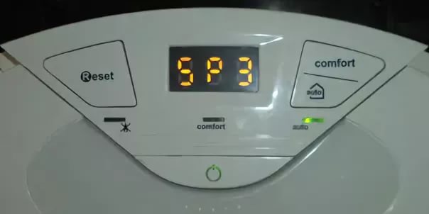
Расшифровка
Отрыв пламени – трактовка ошибки sp3 согласно инструкции на котел Аристон. Неполадка распространенная, с ней сталкиваются в процессе эксплуатации оборудования практически все пользователи. Появление кода – не повод сразу же обращаться к сервисному мастеру. Большинство факторов, вызывающих ошибку sp3, не связаны со сложной поломкой котла Аристон, требующей вмешательства профессионала: код убирается самостоятельно.
Причина отрыва, определяемого ЭПУ, в нестабильном функционировании горелки. Датчик фиксирует пропадание (резкое уменьшение значения) тока ионизации при колебаниях язычков пламени и выдает сигнал, на основе которого формируется ошибка sp3. В Аристон чувствительный элемент установлен на керамической сборке вместе с электродами розжига в камере сгорания (в некоторых моделях – отдельно). На практике код неисправности чаще вызывается внешними факторами, невыполнением регламентных работ в полном объеме, качественно. Начинать поиск причины с учетом надежности итальянского котельного оборудования следует именно с этого.
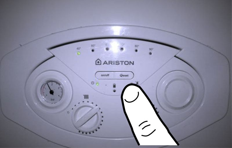
Шаг 1
Нажать кнопку сброса на панели управления.
В котлах Аристон разных моделей, серий обозначается Reset или R. Удержание в течение 5 сек убирает ошибку sp3, если она вызвана сбоем электропитания.
Шаг 2
Оценить состояние датчика ионизации.
Слой пыли, копоти на проволоке (электроде) снижают чувствительность, отсюда ошибка sp3. Почистить, и код неисправности исчезнет. Если в керамике трещина, скол – заменить прибор.
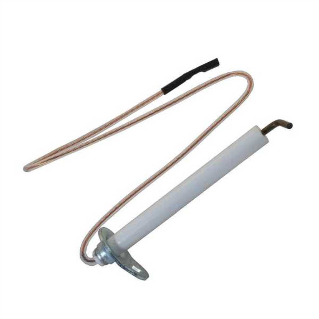
Совет
Убедиться, что расстояние между электродом и металлом горелки 8 мм. В процессе технического обслуживания камеры сгорания, корпуса теплообменника датчик неаккуратным движением сбивается и не реагирует на пламя. Изменение положения вызывает ошибку sp3. Для выравнивания прибора услуги профессионала не требуются.
Внимание: изгибать проволоку датчика нельзя – она хрупкая; только планку, на которой закреплен прибор.
Мнение эксперта
Шаг 3
Проверить параметры сети (U, f).
В инструкции Аристон отмечено, что устойчивая работа котла гарантирована при стабильности напряжения (~230). Отклонение значения на величину свыше ±10% вызывают сбои и ошибки. В частном секторе, в микрорайонах с интенсивной застройкой перекосы фаз, скачки, понижение U – не редкость. При автономном эл/снабжении объекта нужно проверить работу бензогенератора (дизеля), отрегулировать.
Совет
Подключение котла Аристон через ИБП исключает риск появления ошибок по причине нестабильности электропитания. Преимущество блоков перед стабилизаторами существенное, но об этом продавцы последних предпочитают умалчивать.
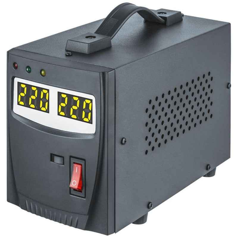
В составе ИБП, кроме схем выравнивания U и заряда, имеются (или подключаются) аккумуляторы. АКБ обеспечивают функционирование оборудования даже при обрывах на ЛЭП. Для загородных строений – идеальное решение.
Шаг 4
Проверить качество заземления.
Производитель обращает внимание, что нарушение требований ПУЭ в этой части – причина ошибок котла Аристон. Ненадежный контакт, окисление, обрыв – и появится код неисправности.
Шаг 5
Проверить тягу.
Проблемы с дымоходом вызывают ошибку sp3. Чрезмерная скорость протока газов по каналу приводит к отрыву пламени. Если она недостаточная, слышится характерный хлопок (на профессиональном сленге это явление именуется проскоком). В любом случае код неисправности вызван нарушением состава горючей смеси, подающейся к форсункам горелки Аристон.
Дефицит кислорода наблюдается при замусоривании воздуховода. При монтаже двухконтурных газовых котлов устанавливаются коаксиальные дымоходы. Нужно проверить, не заблокирован ли тракт инеем, льдом или мусором, а фильтр – пылью. Устранение подобных факторов убирает ошибку sp3.
Совет.
- Диагностика котлов Аристон атмосферного типа проще. Чтобы убедиться, что ошибка sp3 вызвана недостаточным притоком воздуха в камеру сгорания, нужно распахнуть двери, окна. При положительном результате организовать принудительный приток кислорода в комнату. Если в смежном помещении работает мощное вытяжное устройство, отключить. Оно вызывает сбои котла и ошибку sp3. Производитель Аристон обращает особое внимание на недопустимость эксплуатации подобных технических средств поблизости от отопительного агрегата с естественной тягой.
- Появление ошибки sp3 при пуске котла в эксплуатацию – свидетельство просчетов в проектировании, монтаже дымохода. Его параметры рассчитываются с учетом характеристик агрегата (мощности и ряда иных). Несоответствие сечения канала, протяженности, количества поворотов, уклона требованиям производителя вызывают отрыв пламени, ошибку sp3. Случается при самостоятельном обустройстве системы или подключении купленного котла Аристон к имеющейся в доме.
Шаг 6
Тестирование газового тракта. Ошибка sp3 – результат влияния нескольких факторов.
- Нестабильность, пониженное давление в трубе. Проверить несложно по работе газовой плиты. Разжигаются все конфорки (максимальная потребляемая мощность) и визуально оценивается устойчивость язычков пламени, высота, оттенок. Если они меньше обычного, причина ошибки sp3 в нарушении подачи «голубого топлива» к котлу Аристон. При автономном газоснабжении возможна предельная выработка объема газа в резервуаре (баллонная группа, газгольдер).
- Если ошибка sp3 появилась после очередной заправки емкости, причина – в низком качестве газа. С такой проблемой сталкиваются пользователи, желающие сэкономить. Покупка топлива по привлекательной цене, у малоизвестного поставщика приводит к сбоям в работе котла Аристон.
- Обледенение магистрали и технических устройств. В зимнее время оборачивается падением давления в трубе.
- Неполадки приборов, включенных в газопровод: фильтр, счетчик, редуктор. Невыполнение рекомендаций по регулярному обслуживанию, износ теплоизоляции расположенных вне строения объектов, неисправность – причины ошибки sp3 котла Аристон. Проверить, устранить дефект, и код уберется.
Шаг 7
Оценка состояния горелки котла Аристон.
Отрыв пламени происходит при забивании форсунок пылью. Для приготовления горючей смеси кислорода достаточно, а газа не хватает, отсюда и ошибка sp3. Обслуживание с помощью пылесоса и зубной щеточки, аккуратная чистка, и проблема решается за несколько минут.
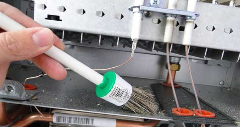
Совет
Одновременно необходимо удалить пыль, нагар с нижней части корпуса теплообменного прибора. В процессе функционирования котла Аристон отложения осыпаются, забивая форсунки горелки.
Шаг 8
Диагностика газового клапана. Его некорректная работа – причина ошибки sp3.
Что проверить
- Сигнальные линии. Ненадежные контакты нарушают управление ГК со стороны ЭПУ котла Аристон. Отсюда нестабильная подача газа к горелке и ошибка sp3.
- Настройки. В инструкции котла Аристон имеется соответствующий раздел. Параметры могут быть сбиты по неаккуратности (невнимательности) пользователя или не выставлены нужные значения после замены узла. Проверить, привести в норму, ошибка sp3 уберется.
- Состояние прибора. Он работает, но падение напора газа вызывается забитостью внутренних каналов протока. Все, что необходимо для устранения неисправности – выполнить обслуживание. В инструкции написано, что такая работа выполняется профессионалом. При самостоятельной чистке клапана главное – не сбить заводские регулировки по давлению (max, min), а потому крутить настроечные элементы нельзя. Ошибка sp3 исчезнет после удаления мельчайших фракций, попавших внутрь ГК из системы газоснабжения.
Шаг 9
Тестирование электронной платы.
С ЭПУ на газовый клапан через реле подаются команды управления. Залипания контактов, приводящие к сбоям в работе ГК – одна из причин (но не единственная) ошибки sp3. Самостоятельно ремонтировать плату не стоит, что бы ни советовали пользователи на тематических форумах. Разные модели котлов Аристов, отличия в уровне подготовки, знаний, опыте людей – аргументов против попыток разобраться самому хватает. Все, что требуется сделать – визуальное тестирование.
Осмотром платы выявляются проблемные участки, детали: оплавления, подгорания, окисления, расколы корпусов, отслоения дорожек. Если на ЭПУ пыль, то чистка тампоном нередко убирает ошибку sp3. Ее слой при впитывании влаги становится токопроводящим, что вызывает сбои в работе ЭПУ и коды неисправностей котла Аристон. В статье изложены подробные рекомендации по устранению ошибки sp3 силами пользователя. «Копать глубже», не имея соответствующей подготовки, нецелесообразно. Итальянский отопительный агрегат стоит дорого, и самостоятельное непрофессиональное вмешательство обернется незапланированными финансовыми расходами. Если своими силами не получилось убрать ошибку, обращаться в сервис. При вызове мастера обязательно указать модель, год выпуска котла Аристон и обозначение ЭПУ (цифры и буквы на плате). Узел меняется, а тестирование проводится в условиях стационара, на стенде-имитаторе. Данное решение не оставит дом без обогрева, не повлечет неоправданных денежных трат.
Поделитесь опытом
Если у вас есть опыт в исправлении ошибки SP3 в газовом котле Ariston — пишите в комментариях к этой статье, мы постараемся рассмотреть ваш вариант и подробно разобрать его в данной или одной из следующих статей. Можете так же присылать фото и видео с комментариями и описанием.
Статья помогла? Сэкономил? Помоги развитию проекта прямо сейчас.
Понравилась статья? Репост будут лучшей благодарностью.
Service Manual
Aitecs 2016
S Y R I N G E I N F U S I O N P U M P
BS049055EN-P01
Prior to servicing this pump, read this manual and the pump’s Operator’s Manual carefully to fully understand the pump’s functionality and to ensure safe and proper servicing.
|
CONTENTS |
|||
|
1. |
INTRODUCTION ………………………………………………………………………………………………………………. |
3 |
|
|
1.1. |
GENERAL INFORMATION ……………………………………………………………………………………….. |
3 |
|
|
1.2. |
GENERAL PRECAUTION………………………………………………………………………………………….. |
3 |
|
|
1.3. |
SERVICE CONTACT …………………………………………………………………………………………………. |
4 |
|
|
2. |
TECHNICAL DESCRIPTION……………………………………………………………………………………………… |
5 |
|
|
2.1. |
GENERAL …………………………………………………………………………………………………………………. |
5 |
|
|
3. |
SERVICE MENU……………………………………………………………………………………………………………….. |
7 |
|
|
3.1. |
MAINTENANCE MENU ……………………………………………………………………………………………. |
7 |
|
|
3.2. |
PROGRAM LOADING……………………………………………………………………………………………….. |
7 |
|
|
3.3. |
MOTOR PROGRAM LOADING …………………………………………………………………………………. |
8 |
|
|
3.4. |
CALIBRATION …………………………………………………………………………………………………………. |
8 |
|
|
3.5. |
TESTING…………………………………………………………………………………………………………………. |
10 |
|
|
4. RECOMMENDED ROUTINE MAINTENANCE AND TESTING ………………………………………… |
13 |
||
|
4.1. AC MAINS / BATTERY OPERATION CHECK …………………………………………………………. |
13 |
||
|
4.2. GENERAL CLEANING AND INSPECTION FOR DAMAGE ……………………………………… |
13 |
||
|
4.3. |
BATTERY TEST………………………………………………………………………………………………………. |
14 |
|
|
4.4. |
INFUSION RATE CHECK ………………………………………………………………………………………… |
14 |
|
|
4.5. OCCLUSION PRESSURE LEVEL CHECK………………………………………………………………… |
14 |
||
|
5. |
TROUBLE-SHOOTING ……………………………………………………………………………………………………. |
15 |
|
|
5.1. |
SAFETY WARNINGS ………………………………………………………………………………………………. |
15 |
|
|
5.2. PUMP HAS BEEN DROPPED OR DAMAGED ………………………………………………………….. |
15 |
||
|
5.3. PUMP HAS BEEN EXPOSED TO FLUIDS ………………………………………………………………… |
15 |
||
|
5.4. TROUBLE-SHOOTING BY FAULT SYMPTOM ……………………………………………………….. |
16 |
||
|
5.5. TROUBLE-SHOOTING BY FAILURE CODES ………………………………………………………….. |
18 |
||
|
6. |
REPAIR …………………………………………………………………………………………………………………………… |
23 |
|
|
6.1. ACCESS TO THE PUMP ………………………………………………………………………………………….. |
24 |
||
|
6.2. FRONT CASE AND SUB-ASSEMBLIES …………………………………………………………………… |
27 |
||
|
6.3. REAR CASE AND SUB-ASSEMBLIES……………………………………………………………………… |
40 |
||
|
6.4. |
TORQUE GUIDE ……………………………………………………………………………………………………… |
47 |
|
|
6.5. |
PART LIST ………………………………………………………………………………………………………………. |
49 |
|
|
7. ELECTRICAL SCHEMATIC DIAGRAMS, COMPONENT LOCATION DIAGRAMS ………….. |
52 |
||
|
7.1. ELECTRICAL BLOCK DIAGRAM OF THE SYRINGE PUMP……………………………………. |
52 |
||
|
7.2. ELECTRICAL SCHEMATIC DIAGRAM OF THE PUMP …………………………………………… |
53 |
||
|
7.3. MAIN ELECTRONIC BOARD COMPONENT LOCATION DIAGRAM ………………………. |
56 |
||
|
7.4. DRIVE UNIT BOARD COMPONENT LOCATION DIAGRAM…………………………………… |
57 |
||
|
7.5. POWER SUPPLY UNIT COMPONENT LOCATION DIAGRAM ………………………………… |
58 |
||
|
8. |
SPARE PARTS LISTING………………………………………………………………………………………………….. |
59 |
|
|
8.1. |
SPARE ACCESSORIES ……………………………………………………………………………………………. |
59 |
|
|
8.2. SPARE LABELS / PUBLICATIONS ………………………………………………………………………….. |
59 |
||
|
8.3. |
SPARE ELECTRICAL COMPONENTS……………………………………………………………………… |
60 |
|
|
8.4. |
SPARE MECHANICAL COMPONENTS …………………………………………………………………… |
60 |
|
|
ANNEX A ROUTINE MAINTENANCE & CHECKOUT PROCEDURE…………………………………… |
61 |
|
Aitecs 2016 Service Manual |
2 |
1.INTRODUCTION
1.1.GENERAL INFORMATION
The AITECS 2016 syringe pump is designed to accurately control the delivery of solution to the patient by means of a disposable syringe.
The AITECS 2016 syringe pump is compatible with a wide range of standard, single-use, disposable Luer-lock syringes, ranging from 5 ml to 60 ml in size.
This SERVICE MANUAL describes the theory of operation, how to check, troubleshoot and repair AITECS 2016 syringe infusion pump.
Ensure that you are fully familiar with this equipment by carefully studying the Operator’s Manual and this Service Manual prior to attempting any repairs or servicing.
1.2.GENERAL PRECAUTION
Please read the general Operating Precautions described in the Operator’s Manual carefully prior to using this syringe pump.
This pump contains static-sensitive components. Observe strict precautions for the protection of static sensitive components when attempting to repair and service the syringe pump.
An explosion hazard exists if the syringe pump is used in the presence of flammable materials. Exercise care to locate the pump away from any such hazardous sources.
An electrical shock hazard exists if the syringe pump casing is opened or removed. Refer all servicing to qualified service personnel.
This syringe pump is protected against the effects of high energy radio frequency emissions and is designed to fail safe if extremely high levels of interference are encountered. Should false alarm condition be encountered, either remove the source of the interference or regulate the infusion by another appropriate means.
|
Aitecs 2016 Service Manual |
3 |
If the syringe pump is dropped, subjected to excessive moisture, humidity or high temperature, or otherwise suspected to have been damaged, remove it from service for inspection by qualified service personnel.
1.3.SERVICE CONTACT
VILTECHMEDA, 125 Kalvarijų Str., 08221 Vilnius, Lithuania
E-mail: service@aitecs.com
Tel. : +370-52-737509
|
Aitecs 2016 Service Manual |
4 |
2.TECHNICAL DESCRIPTION
2.1.GENERAL
The Block Diagram of the syringe pump is given in the section 7.1. The Electrical Schematic Diagram is given in the section 7.2. The syringe pump is composed of the following elements:
—Keypad
—Syringe barrel sensor
—Syringe size sensor
—Main Electronic board (MEB)
—Pusher sensors unit
—Motor
—Encoder
—Pressure sensor
—Pusher home sensors
—Drive Unit board
—Switching power supply
—Battery unit
—IrDA unit
—Power supply unit
Below follows a description of these elements, refer the appropriate diagram for full understanding of the functionality:
2.1.1.Keypad
Keypad comprises of a 6 x 4 key matrix connected to the Main Electronic board at connector JP3. ON/OFF key, C key and BATTERY & MAINS LED’s are also located on the keypad.
2.1.2.Syringe barrel sensor
The syringe barrel sensor comprises photo interrupter D1. When the syringe is loaded, the shutter is drawn out of the slot of the photo interrupter D1, enabling its optical link. The LED of the photo interrupter is supplied with pulse-modulated current through pin 3 of JP4 connector of the Main Electronic board.
2.1.3.Syringe size sensor
The syringe size sensing is achieved using the linear potentiometer R1. The signal from the potentiometer slider is applied to the Main Electronic board via pin 2 of JP8 connector.
2.1.4.Pusher sensors unit
The plunger push-button sensors are composed of two photo interrupters D1, D2. The grippers latched sensor comprises photo interrupter D3. The LED’s of the photo interrupters are supplied with pulse-modulated current through pin 3 of JP8 connector of the Drive Unit board.
When the syringe is loaded, the shutter is outside the slot of D1 is and inside the slot of D2. When the syringe is loaded, the shutter controlling the photo interrupter D3 is outside of its slot.
|
Aitecs 2016 Service Manual |
5 |
2.1.5.Motor
A two-phase bipolar stepper motor with 1.8º step-angle is used in the pump drive. The motor is connected to the Drive Unit board via connector P6 and is driven in micro stepping mode. There are 200 steps to complete one full revolution of the motor shaft. The motor is connected to the lead screw by means of timing belt. The belt ratio is 1.6(6):1; as a result 333.3(3) motor steps move the drive carriage by 1.25 mm.
2.1.6.Encoder
Motor speed and direction is monitored by means of the encoder. It is composed of two photointerrupters D1, D2 and a 12 slot-encoding disk mounted on the lead screw. Quadrature signals (Tax1, Tax2) are transferred to the Drive Unit board via JP5 connector.
2.1.7.Pressure sensor
As a pressure sensor is used a strain gauge TZ1 mounted on a steel plate. When this plate is deflected by applied force on the plunger, a differential voltage is generated at gauge output. This signal, which magnitude is proportional to the applied force, is transferred to the Drive Unit board.
2.1.8.Pusher home sensor
The pusher home sensors are composed of two photo interrupters D1, D2. When the syringe pusher is in the right end position, the shutter is outside the slot of D1 is and inside the slot of D2.
2.1.9.Switching power supply
A 30W single output 12V, 2.5A medical type switching power supply is used in the pump.
2.1.10. Battery unit
The battery unit comprises the Ni-MH (7,2V x 2.5Ah) battery GB1 together with the battery monitoring circuit. The integrated circuit U1 monitors battery voltage, temperature and charge/discharge current. This data is used to calculate battery charge state and remaining working time when pump runs on battery. Data is transferred to the microcontroller via 1-Wire interface (pin 4 of the JP1 connector). R2 is a current sense resistor; R3 and C1 constitute a low pass filter for the current monitoring circuit. Thermistor R1 terminates battery charging if battery temperature exceeds the permissible value. The resettable fuse F1 protects against a short circuit of the battery.
2.1.11. IrDA unit
Serial infrared data communication is operating in accordance with the IrDA standard using modulator-demodulator U1 and transceiver U2. The transceiver is mounted on the rear of the PCB, in front of the window at the back of the pump. The window is covered with dark IRtransparent plastic.
|
Aitecs 2016 Service Manual |
6 |
3. SERVICE MENU
While keeping pressed the key turn the pump on. Enter code 751 using the numerical
keypad. Press OK to confirm the code. The Service Menu will be displayed. Use the keys to select the required parameter.
3.1.MAINTENANCE MENU
Select the MAINTENANCE MENU from the Service menu and press the OK softkey. Use the
keys to select the required parameter. Press the OK softkey:
—to set DEFAULT PARAMETERS
—to modify the NEXT SERVICE DATE
—to view the selected LOG (event, use, key or service)
—to set ALARM PITCH
—to set ALERT PITCH
—to view serial number
Press the BACK softkey to return to Service menu.
3.2.PROGRAM LOADING
3.2.1.Loading main program
To perform a programming operation, the following is required:
—A2016 Firmware Upload Utility must be installed and configured on the computer that is being used.
—Either USB cable must be connected between the USB port of the computer and the USB connector in the rear of the pump.
While keeping pressed the key, turn the pump on. The Loader USB message shall appear on the screen. The pump is ready for loading the program.
Programming sequence:
—Start A2016 Firmware Upload Utility application by clicking on the appropriate icon.
—Select USB interface.
—Click on Firmware key in order to load program.
—Click on Firmware key to start the programming operation.
When programming completed switch off the pump using the ON/OFF key. Having loaded new program it is necessary to set DEFAULT PARAMETERS and execute full testing (see Section 3.4.1).
3.2.2. Loading Bootstrap
In order to perform a programming operation, the following should be in place:
— A2016 Firmware Upload Utility should be installed and configured on the computer that is being used.
|
Aitecs 2016 Service Manual |
7 |
— Having opened the pump housing, Bootstrap Loader Unit should be connected between the Main Electronic board connector JP7 and the COM port of the computer. Bootstrap Loader Unit switch should be in ON position.
Switch on the pump. Press the Reset key on the Bootstrap Loader Unit. The pump is now ready to download a Bootstrap.
Programming sequence:
—Start A2016 Firmware Upload Utility application by clicking on the appropriate icon.
—Select which COM port is going to be used.
—Click on Bootloader key in order to load Bootstrap.
—Click on Bootloader key to start the programming operation.
After Bootstrap downloading process is completed, it is necessary to switch Bootstrap Loader Unit switch into OFF position and to press the Reset key.
Having loaded new bootloader it is necessary to set DEFAULT PARAMETERS and execute full testing (see Section 3.4.1).
3.3.MOTOR PROGRAM LOADING
To perform a programming operation, the following is required:
—A2016 Firmware Upload Utility must be installed and configured on the computer that is being used.
—Either USB cable must be connected between the USB port of the computer and the USB connector in the rear of the pump.
Select the MOTOR PROGRAM LOADING and press the OK softkey. The MOTOR PROGRAM UPGRADE message shall appear on the screen. The pump is ready for loading the motor program.
Programming sequence:
—Start A2016 Firmware Upload Utility application by clicking on the appropriate icon.
—Select USB interface.
—Click on Motor key in order to load program.
—Click on Motor key to start the programming operation.
When programming completed switch off the pump using the ON/OFF key. Having loaded new program it is necessary to set DEFAULT PARAMETERS and execute full testing (see Section 3.4.1).
3.4.CALIBRATION
Select the CALIBRATION from the Service menu and press the OK softkey. Select item to be calibrated using the keys and press the OK softkey.
|
Aitecs 2016 Service Manual |
8 |
3.4.1. Syringe size calibration
The syringe size detection system stores the characteristics of the syringe clamp assembly, including the travel of the linear potentiometer in non-volatile memory.
Equipment:
—Spacer (gauge) SP0 (B8640027-04);
—Spacer (gauge) SP1 (B8640037-01);
—Spacer (gauge) SP2 (B8640037-02);
—Spacer (gauge) SP3 (B8640037-03).
Select the Syringe size from calibration menu and press the OK softkey. With the syringe clamp at the lowermost position press the OK softkey. One after another insert spacers from 0 to 3, each time closing the syringe clamp and pressing the OK softkey to acknowledge. Finally fix the syringe clamp at the uppermost position and again press the OK softkey.
3.4.2. Pusher button and pusher position calibration
Equipment:
—Calibration spacer (gauge) SP1 (B8640037-01).
Select the Pusher button & pusher position from calibration menu and press the OK softkey. Press the pusher lever if appropriate message appears. When display reads the Insert spacer SP1 and press OK message, insert the SP1 spacer and press the OK softkey. Syringe pusher shall move forward until it comes in contact with the spacer. When syringe pusher stops automatically and display reads a CONFIRM softkey, press the CONFIRM softkey.
3.4.3. Force (pressure) calibration
Equipment:
—Digitron pressure meter, model: 2022P (0-1500 mmHg);
—50 ml BD PLASTIPAK or 60 ml BD syringe with extension line.
Screws fastening rear case to front case must be unscrewed.
Select the Force sensor from calibration menu and press the OK softkey. Then follow directions on the display.
When the Is pusher free? message appears, make sure that pushing surface of the retainer is not in contact with any part of pump or extraneous object.
When Adjust readings… message appears check the value indicated at left bottom corner of screen and adjust it, if out of above indicated on the screen range, by means of potentiometer R30 on the Drive Unit.
Upon prompt of inserting syringe, fill syringe with 10-20 ml of water, and fit it to the pump. Connect pressure meter to the syringe by means of the extension line. Locate the pressure meter at the same height as the syringe and press the OK softkey.
After the pusher comes in contact with syringe plunger press the > softkey and keep it depressed, allowing the transmission to run until the pressure meter reads (120±1.5) cmHg. When approaching the target value, it is recommended to run transmission in short steps, pressing the > key momentarily. If you fail to stop movement timely and target value is overridden, calibration procedure must be repeated from the beginning.
When pressure is adjusted as required, press the OK softkey. Press the BACK softkey to exit.
|
Aitecs 2016 Service Manual |
9 |
NOTE. When calibrating force sensor after repairing or replacing drive or pusher, it is necessary to go through described above procedure three times, first and second time running transmission until pressure goes to 140-150 cmHg, and the last time – exactly as described.
3.4.4. Battery capacity calibration
Battery capacity calibration cycles the battery through a charge, discharge, re-charge sequence during which the fuel gauge within the Battery Unit will be updated with a measurement of the current capacity of the cells.
This calibration allows the fuel gauge to monitor accurately the charge in the pack. Over time the estimate of capacity may drift from the actual cell capacity, which generally decreases with time.
Recalibration will update the fuel gauge with the measured capacity of the cells.
Remove the battery pack lid to ensure a stable pack environment during calibration. It is recommended that the pack is removed from the battery compartment and placed behind the pump. Connect the pump without syringe to the mains.
Select the Battery Capacity from calibration menu and press the OK softkey. Press START softkey in the following window. Leave pump in calibration mode for up to 20 hours. The cycle should run passing automatically three phases one by one:
•Initial charge phase – up to 4 hours
•Measured discharge phase. Pack is discharged using typical load down to 1.1 V per cell to determine how much charge is available from the pack – up to 12 hours
•Final charge phase. Pack is fully recharged ready for use. Early in this phase the measured discharge value is transferred to the pack gas gauge to be stored as the new capacity (mAh).
During the course of calibration the battery related information is displayed on the pump screen. At the end the CALIBRATION COMPLETED message appears. Press the BACK softkey to exit.
3.5.TESTING
Select the TESTING from the Service menu and press the OK softkey. Select the item to be tested using the keys and press the OK softkey.
3.5.1. Full testing
This section provides a complete pump test procedure. Follow each stage test and follow the instructions on the display use the NEXT softkey to move to the other test.
3.5.2. Program testing
This test is intended to calculate program and bootstrap CRC. Select the Program from testing menu and press the OK softkey. Software version, bootstrap version and calculated CRC values are indicated in the display. Press the BACK softkey to return to TESTING menu.
|
Aitecs 2016 Service Manual |
10 |
3.5.3. Drive sensors test
This test enables checking of the following sensors: pusher home, pusher button, grippers unlatch and syringe barrel.
Select Drive Sensors from the testing menu and press the OK softkey.
Home sensors can be checked moving pusher by means of the < and > soft keys and watching number of home zone indicated on screen. Zone 0 should be indicated when pusher is at the rightmost position, and zone number shall shift in order to 1, 2, and 3 when moving pusher to the left. Zone 3 indication shall appear not more than 10 mm from the rightmost position and shall be retained all the rest way to the left.
Pusher sensors can be checked pressing smoothly pusher button with finger and watching number of pusher zone indicated on screen (grippers must be in open position). While pusher button is released, the zone C shall be indicated. As pressure on button increases, zone indication shall switch in order to B, and C.
To check unlatch sensor, open pusher grippers and make sure that status of unlatch sensor indicated on the display is OFF. Press the UNLATCH softkey. Grippers shall close and status of unlatch sensor shall change to ON.
Once complete press the BACK softkey to return to TESTING menu.
3.5.4. Syringe size test
This test is enables checking the operation of syringe size sensor.
Select Syringe size sensor from the testing menu and press the OK softkey. Slowly lift the syringe clamp. Check if syringe size sensor value changes (mV and mm). Having finished testing press the BACK softkey to return to TESTING menu.
3.5.5. Pusher position test
This test enables checking pusher position calibration. Select Pusher position sensor from the testing menu and press the OK softkey. Insert the SP1 spacer. Press the OK softkey. Syringe pusher shall move until coming into contact with the spacer. Pusher position value of
(22 ± 0.5) mm should be indicated on the display. Having finished testing press the BACK softkey to return to TESTING menu.
3.5.6. Motor test
This test enables checking motor operation. During test no syringe should be installed. Select
Motor from the testing menu and press the OK softkey. Keep the < softkey depressed and make
sure that pusher moves to the left. Check reverse movement when > key is depressed. Having finished testing press the BACK softkey to return to TESTING menu.
3.5.7. Display test
This test checks that all of the display pixels (256×64) illuminate. Select Display from testing menu and press the OK softkey. Observe “chess-board” structure fields that appear in the
|
Aitecs 2016 Service Manual |
11 |
display. All the rectangles should be same shaped and evenly filled. Having finished testing press the BACK softkey to return to TESTING menu.
3.5.8. Nurse call test
Equipment:
—Nurse call cable (B6650034);
—Ohmmeter.
This test checks the nurse call circuit operation. Select Nurse call from testing menu and press the OK softkey. Using a meter check the circuit between the Nurse call contact 9 (com) and contacts 10 (NO), 8 (NC). The contacts should toggle each time the CHANGE softkey is pressed, as indicated on the display. Press the BACK softkey to return to TESTING menu.
3.5.9. Speaker/buzzer test
This test checks the speaker and buzzer operation. Select Speaker/buzzer from the testing menu and press the OK softkey. Check for the alternating volume sound from the speaker. Check for the sound from the buzzer. Press the BACK softkey to return to TESTING menu.
3.5.10. Keypad test
This test enables checking the keypad operation. Select Keypad from the testing menu and press the OK softkey. Press one by one all keys and make sure that after pressing any key its image on the display is highlighted. Press the BACK softkey to return to TESTING menu.
NOTE. This test does not apply to the ON/OFF key.
3.5.11. LEDs test
This test is intended to check the LED operation. Select LEDs from testing menu and press the OK softkey. The following LEDs should activate one after another: GREEN (INFUSION), RED (ALARM), YELLOW(ALERT) and BATTERY. In order to check the operation of BATTERY LED it is necessary to connect the power cable. In order to check the operation of MAINS LED it is necessary to remove and reconnect the power cable. Press the BACK softkey to return to TESTING menu.
In order to check the operation of red backup battery LED it is necessary to remove the power supply cable from Main electronic board.
3.5.12. Watch-dog test
This test enables checking of the watch-dog circuit operation. Select Watch-Dog from testing menu and press the OK softkey. Clocking of the watch-dog circuits is interrupted for certain time. This shall trigger watch-dog, which activates red alarm LED and launches the buzzer. When test completed switch off the pump using the ON/OFF key.
|
Aitecs 2016 Service Manual |
12 |
4. RECOMMENDED ROUTINE MAINTENANCE AND TESTING
It is recommended that routine maintenance be carried out at least once a year. This should include (see Annex A):
—AC Mains / Battery operational checks (section 4.1).
—General cleaning and inspection for damage (section 4.2).
—Battery test (section 4.3).
—Infusion rate check (section 4.4).
—Occlusion pressure level check (section 4.5).
—Full test (sections 3.4.1-3.4.12).
4.1.AC MAINS / BATTERY OPERATION CHECK
Switch the pump on and plug pump into the mains. Observe that the MAINS indication LED becomes illuminated. Remover the mains supply and observe that the MAINS LED switches off. Observe that the battery indication LED becomes illuminated as the mains supply is removed.
4.2.GENERAL CLEANING AND INSPECTION FOR DAMAGE
To ensure that this pump remains in good operating condition, it is important to keep it clean and carry out the routine procedures described below. Only a qualified service engineer, with reference to this manual, should perform servicing. The following routine maintenance procedures should be carried out as required but at least once per year:
Thoroughly clean external surfaces of the pump before and after prolonged periods
of storages by wiping a lint-free cloth lightly dampened with warm water and standard disinfectant/detergent solution.
Disinfectants known to be corrosive to metals and plastics must not be used.
Before cleaning always switch OFF and disconnect from the AC power supply.
Never allow liquid to enter the casing and avoid excessive fluid build up on the pump.
Do not use aggressive cleaning agents as these may damage the exterior surface of the pump.
Do not steam autoclave, ethylene oxide sterilize or immerse this pump in any fluid.
Check Labels should be flat and legible. Replace as required
Case components must be checked for damage that may affect function, present fluid ingress routes and present a user hazard must be replaced as necessary.
Check the mounting clamp is not damaged and that it functions correctly.
Inspect the AC power supply inlet and cable for sings of damage.
|
Aitecs 2016 Service Manual |
13 |
4.3.BATTERY TEST
Perform battery calibration in accordance with 3.3.5. When calibration is completed and the battery is fully charged (at least 5 hours on charge) disconnect the pump from the mains. Load 50 ml BD Plastipak syringe with the plunger at 60.0 ml position on the syringe barrel scale. Set the 5.0 ml/h rate and start infusion (see the Operator’s Manual for further information on starting the pump).
Normally pump should be able to work on battery for about 10 hours. If this time is significantly less battery should be replaced.
After completion of the test the pump should be recharged for a minimum of 3 hours.
4.4.INFUSION RATE CHECK
Equipment:
—stop-watch;
—graduated glass test-tube (one point equals to 0.1 ml, volume 60ml or more).
Take the BD Plastipak 50 ml syringe with extension set and fill it with distilled water up to point of 60ml. Program the following infusion parameters:
—Rate 50 ml/h.
Insert the free end of extension set into the test-tube and start the infusion. Measure infusion time with the stop-watch till the moment pump display indicates 50 ml infused and stop the infusion. Read the volume of water delivered into the test-tube. Calculate the infusion rate. It shall be 50ml/h ±1ml/h (±2%).
4.5.OCCLUSION PRESSURE LEVEL CHECK
Equipment:
—Digitron pressure meter, model: 2022P (0-1500mmHg).
Fill the 50 ml BD Plastipak syringe with 20-30 ml of the distilled water and connect it to the pressure meter using the extension set. Switch on the pressure meter and set the max/min pressure recording mode.
Set pump occlusion alarm level to L-10 and launch infusion at 5 ml/hr rate (for pump operation details refer to the Operator’s Manual).
When pump will stop and indicate OCCLUSION read the maximum pressure recorded by pressure meter. Readings shall be within (73 -117) cmHg range.
If recorded value is outside this range, re-calibrate the force sensor in accordance with 3.3.4 and repeat this test.
|
Aitecs 2016 Service Manual |
14 |
5.TROUBLE-SHOOTING
5.1.SAFETY WARNINGS
—Use extreme caution when pump whilst it is connected to the AC mains.
Hazardous voltages are present at the mains inlet and on the power supply even the pump is switched off.
—Disconnect the battery and AC power whenever removing or inserting PCBs or
|
other connectors. |
|
|
— |
This pump contains static-sensitive components. Wherever the ESD |
symbol appears observe strict precaution for the protection of static-sensitive components when attempting to service and repair the pump.
—Always visually inspect the pump, power cord and plug for damage. If the power
cord or plug is damaged they should be replaced.
5.2.PUMP HAS BEEN DROPPED OR DAMAGED
If the pump is dropped or damaged, the damaged parts should be identified and replaced before any further troubleshooting is carried out.
During inspection, careful attention should be paid to the front and rear case halves, for signs of drop damage. Also check the pump drive, syringe pusher and syringe size sensor.
5.3.PUMP HAS BEEN EXPOSED TO FLUIDS
Excessive fluid spills can lead to fluid ingress into the pump. Even if the fluid dries out, deposits can be left which cause the pump to fail.
If fluid ingress is suspected the pump should be inspected internally.
Clean and dry out the pump.
Take care to ensure dried deposits do not remain on the PCBs or other electrical components. Replace any damaged PCBs or components.
|
Aitecs 2016 Service Manual |
15 |
5.4.TROUBLE-SHOOTING BY FAULT SYMPTOM
|
SYMPTOM |
CHECK |
CORRECTIVE ACTION |
|
Pump does not operate from |
Check mains cord. |
Replace mains cord. |
|
external AC mains (MAINS |
Check switching power |
Replace switching power |
|
LED does not operate). |
supply. |
supply if necessary. |
|
Pump does not operate from |
Check 12VDC & Nurse call |
Replace 12VDC & Nurse call |
|
external 12 VDC (MAINS |
connector unit. |
connector unit. |
|
LED does not operate). |
||
|
Pump operates from the AC |
||
|
mains. |
||
|
One or more keypad key |
Perform keypad test. |
Replace keypad. |
|
presses are not accepted. |
||
|
Too high or too low contrast |
Check contrast setting. |
Adjust the contrast as |
|
level. |
described in Operator’s |
|
|
Manual. |
||
|
Check the voltage of the |
Adjust voltage by means of |
|
|
Main Electronics Board test |
R27, if the problem persists – |
|
|
point TP4. The value should |
replace the Main Electronic |
|
|
be (-5.8±0.1)V, when |
board. |
|
|
contrast is set to level 6. |
||
|
Backlight does not operate |
Check backlight setting. |
Adjust the backlight as |
|
when pump is powered on. |
described in Operator’s |
|
|
Manual. |
||
|
Check backlight circuit |
Replace Main Electronic |
|
|
interconnection on Electronic |
board if necessary. |
|
|
board. |
||
|
Check the Display Unit and |
Replace Display Unit if |
|
|
its connection to Electronic |
necessary. |
|
|
board connector JP2. |
||
|
Second (high pitch) audible |
Check buzzer (Z1) in the |
Replace buzzer (Z1). |
|
alarm does not sound after |
Main Electronic board. |
|
|
power on. |
Check backup battery GB1 in |
Replace backup battery GB1. |
|
the Main Electronic board. |
||
|
Grippers do not close when |
Perform drive sensors test |
Replace syringe pusher if |
|
loading syringe. |
(Pusher). |
necessary. |
|
Check the capacitor C1 and |
Replace capacitor unit. |
|
|
its connection to Drive Unit |
||
|
board. |
||
|
Check the electromagnet |
Replace syringe pusher if |
|
|
circuit and its connection to |
necessary. |
|
|
Drive Unit board. |
||
|
When loading syringe, after |
Perform drive sensors test |
Replace syringe pusher if |
|
closing grippers the Press |
(Unlatch). |
necessary. |
|
lever prompt is displayed. |
||
|
Aitecs 2016 Service Manual |
16 |
|
Check syringe prompt is |
Perform drive sensors test |
Replace syringe barrel sensor |
|
displayed when loading |
(Barrel). |
if necessary. |
|
syringe. |
Check the syringe barrel |
|
|
sensor connection to Main |
||
|
Electronic board. |
||
|
Pusher home sensors do not |
Perform drive sensors test |
Replace pusher home sensor |
|
work properly (screen |
(Home). |
unit if necessary. |
|
indicates internal |
Check home sensors unit |
|
|
malfunction after switching |
connection to Main |
|
|
on the pump). |
Electronic board. |
|
|
Syringe size sensor does not |
Test syringe size sensor (see |
Calibrate syringe size sensor |
|
determine syringe size |
section 3.4.4). |
(see section 3.3.1). |
|
properly. |
Check the syringe size sensor |
Replace syringe size sensor if |
|
and its connection to Main |
necessary. |
|
|
Electronic board. |
||
|
Occlusion pressure level |
Check occlusion pressure |
Calibrate pressure sensor |
|
incorrect. |
level (see section 4.5). |
(see section 3.3.4). |
|
Check pressure sensor |
Replace syringe pusher if |
|
|
connection to Drive Unit |
necessary. |
|
|
board. |
||
|
Check pressure sensor |
Replace Drive Unit board if |
|
|
amplifier circuit. |
necessary. |
|
|
Too short operation time on |
Test battery (see section 4.3). |
Replace battery unit if |
|
battery. |
necessary. |
|
|
Nurse Call does not operate. |
Perform Nurse Call test. |
Replace 12VDC & Nurse |
|
call connector unit. |
||
|
Check nurse call circuit |
Replace Power Supply unit if |
|
|
interconnection on Power |
necessary. |
|
|
Supply unit. |
||
|
USB interface does not |
Check USB connector unit. |
Replace USB connector unit. |
|
operate. |
Check USB cable. |
Replace USB cable. |
|
Check USB circuits on Main |
Replace Main Electronic |
|
|
Electronic board. |
board if necessary. |
|
|
IrDA interface does not |
Check the connection of |
Replace IrDA unit if |
|
operate (when link to |
IrDA unit to Main Electronic |
necessary. |
|
AIMS 16 is enabled in user |
board. |
|
|
configuration menu). |
Check IrDA circuits. |
|
|
Mounting clamp cannot be |
Check mounting clamp. |
Replace mounting clamp. |
|
fixed to the pump. |
|
Aitecs 2016 Service Manual |
17 |
5.5.TROUBLE-SHOOTING BY FAILURE CODES
|
CODE |
DESCRIPTION |
CORRECTIVE ACTION |
|
|
AB01 |
During antibolus motor has exceeded the |
Power off then on. If failure code |
|
|
step count limit. |
recurs, replace drive unit board |
||
|
software. If the problem persists, |
|||
|
replace drive unit board if necessary. |
|||
|
BAR01 |
Barrel sensor is damaged. |
Check barrel sensor and replace it if |
|
|
necessary. |
|||
|
BP00 |
Corrupted configuration parameters. |
Set default parameters in Service |
|
|
menu/Maintenance menu. If failure |
|||
|
code recurs, replace Main electronic |
|||
|
board if necessary. |
|||
|
BP01 |
Configuration parameters out of limits. |
Set default parameters in Service |
|
|
menu/Maintenance menu. If failure |
|||
|
code recurs, replace Main electronic |
|||
|
board if necessary. |
|||
|
BT00 |
Communications with the battery fuel gauge |
Inspect cables between Battery unit, |
|
|
has failed. |
Power supply unit and Main |
||
|
Electronic board. |
|||
|
BT02 |
The battery cell voltage is low (less than |
Charge battery, if failure code recurs, |
|
|
1.05V per cell). |
replace Battery Unit if necessary. |
||
|
BT03 |
The battery cell voltage is high (greater than |
Check battery charge circuit and |
|
|
1.75V per cell). |
replace power supply unit if |
||
|
necessary. |
|||
|
BT04 |
The battery temperature is high (greater than |
Check battery charge circuit and |
|
|
60°C). |
replace power supply unit if |
||
|
necessary. |
|||
|
BT05 |
The battery charging current is high (greater |
Check battery charge circuit and |
|
|
than 1.5A). |
replace power supply unit if |
||
|
necessary. |
|||
|
BT06 |
The battery discharging current is high |
Disconnect one by one all the |
|
|
(greater than 1.5A). |
connectors, find current leakage place |
||
|
and replace faulty unit. |
|||
|
BT07 |
The battery is discharging whilst the pump is |
Inspect cables between battery |
|
|
on the mains. |
Monitoring and Power Supply Unit. |
||
|
Check battery charge circuit and |
|||
|
replace Power Supply Unit if |
|||
|
necessary. |
|||
|
BVXX |
Bad variable |
Power off then on. If failure code |
|
|
recurs, replace MEB software or |
|||
|
Main electronic board if necessary. |
|||
|
EE00 |
Cannot read/write data from/to external |
Power off then on. If failure code |
|
|
EEPROM |
recurs, replace Main electronic board |
||
|
if necessary. |
|||
|
FL01 |
Internal Flash timout |
Power off then on. If failure code |
|
|
recurs, replace Main electronic board |
|||
|
if necessary. |
|
Aitecs 2016 Service Manual |
18 |
|
CODE |
DESCRIPTION |
CORRECTIVE ACTION |
|
|
FL03 |
Internal Flash trap |
Power off then on. If failure code |
|
|
recurs, replace Main electronic board |
|||
|
if necessary. |
|||
|
HT01 |
External NMI activated |
Power off then on. If failure code |
|
|
recurs, replace MEB software if |
|||
|
necessary. |
|||
|
HT02 |
Stack overflow |
Power off then on. If failure code |
|
|
recurs, replace MEB software if |
|||
|
necessary. |
|||
|
HT03 |
Stack upperflow |
Power off then on. If failure code |
|
|
recurs, replace MEB software if |
|||
|
necessary. |
|||
|
HT04 |
Internal microcontroller trap activated (Class |
Power off then on. If failure code |
|
|
B) |
recurs, replace MEB software if |
||
|
necessary. |
|||
|
KY01 |
Keypad key has been depressed for 5 |
Replace keypad if necessary. |
|
|
minutes. |
|||
|
LOG1 |
Key log has failed |
Power off then on. If failure code |
|
|
recurs, replace Main electronic board |
|||
|
if necessary. |
|||
|
LOG2 |
Error log has failed |
Power off then on. If failure code |
|
|
recurs, replace Main electronic board |
|||
|
if necessary. |
|||
|
LOG3 |
Event log has failed |
Power off then on. If failure code |
|
|
recurs, replace Main electronic board |
|||
|
if necessary. |
|||
|
OS01 |
Operating system timeout |
Power off then on. If failure code |
|
|
recurs, replace MEB software if |
|||
|
necessary. |
|||
|
OTHXX |
Other failures |
Check log, if necessary replaces MEB |
|
|
software. |
|||
|
PP01 |
Pusher position readings out of range for the |
Calibrate pusher home and syringe |
|
|
inserted syringe. |
size sensors. If the problem persists, |
||
|
check and replace pusher home |
|||
|
sensor or syringe size sensor if |
|||
|
necessary. |
|||
|
PP02 |
Pusher home sensor failure |
Check and replace pusher home |
|
|
sensor if necessary. |
|||
|
PP03 |
Pusher home sensor failure |
Check and replace pusher home |
|
|
sensor if necessary. |
|||
|
PR01 |
Incorrect MEB soft Bootstrap CRC |
Power off then on. If failure code |
|
|
recurs, replace MEB Bootstrap |
|||
|
software if necessary. |
|||
|
PR02 |
Incorrect MEB program CRC |
Power off then on. If failure code |
|
|
recurs, replace MEB software if |
|||
|
necessary. |
|
Aitecs 2016 Service Manual |
19 |
Loading…
- About
- Blog
- Projects
- Help
-
Donate
Donate icon
An illustration of a heart shape - Contact
- Jobs
- Volunteer
- People
Bookreader Item Preview
texts
Aitecs 2016 Syringe Infusion Pump Service Manual
Aitecs 2016 Syringe Infusion Pump Service Manual
- Addeddate
- 2020-05-20 03:44:25
- Classification
- Clinical;Infusion and Syringe Pump;Aitecs Infusion Pump;Aitecs 2016
- Identifier
- manual_Aitecs_2016_Syringe_Infusion_Pump_Service_Manual
- Identifier-ark
- ark:/13960/t4km82s7x
- Ocr
- ABBYY FineReader 11.0 (Extended OCR)
- Page_number_confidence
- 100.00
- Ppi
- 600
- Scanner
- Internet Archive Python library 1.9.0
comment
Reviews
There are no reviews yet. Be the first one to
write a review.
SIMILAR ITEMS (based on metadata)

Свяжитесь с нами: +7 495 649-09-41
Высокоточный шприцевой насос с автоматическим захватом шприца
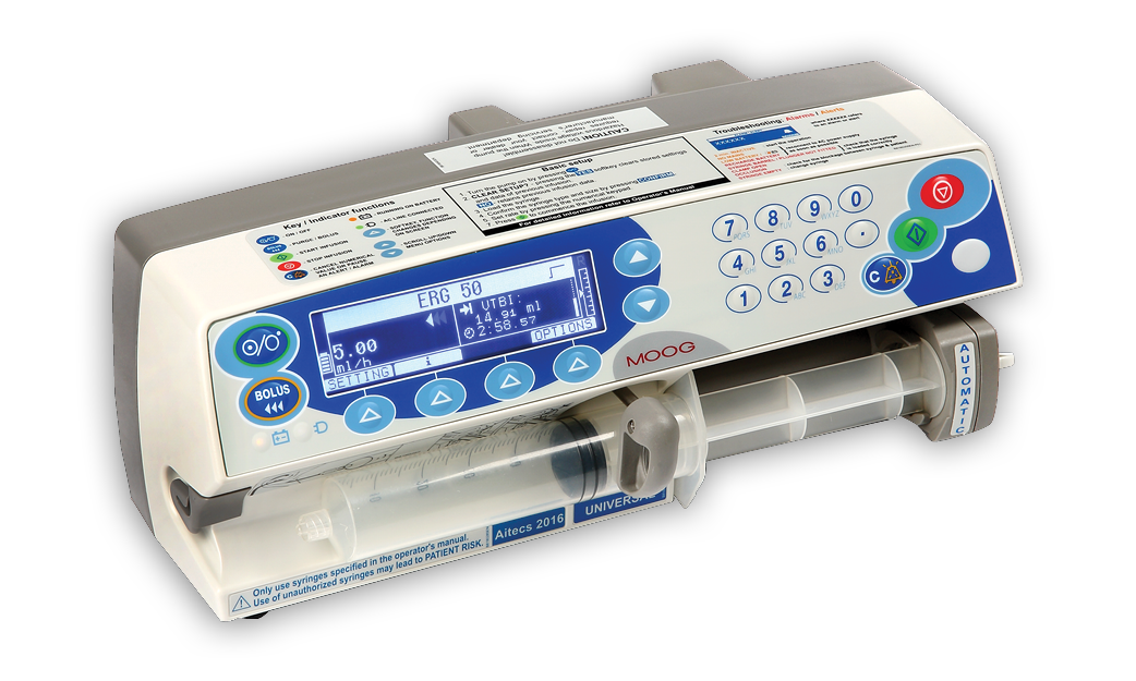
ОБЗОР
Aitecs 2016 предназначен для точного и непрерывного дозирования растворов, вводимых с помощью шприцев в различных областях медицины (в палатах общего профиля, отделениях интенсивной терапии и реанимации, отделениях для новорожденных, операционных и отделениях неотложной помощи).
Насос предназначен для инфузии через внутривенные, энтеральные, подкожные или эпидуральные пути введения.
+7 495 649 09 41 / info@viltechmeda.ru
Режимы инфузии
Всего в aitecs 2016 предусмотрено 5 режимов инфузии:
— постоянная скорость (мл/час),
— расчёт скорости по объему и времени,
— расчет скорости по доза и времени,
— прерывистый режим,
— TIVA (общая внутривенная анестезия).
Автоматический захват шприца
При начале работы насоса aitecs 2016 толкатель автоматически подходит к заггруженному шприцу и захватывает его. Такая система сводит к минимуму возможность непреднамеренного болюса при установке шприца и значительно ускоряет начало поступления лекарственного препарата пациенту .
Подключение к системе
aitecs 2016 совместим с нашей системой инфузионного мониторинга (AIMS16), системами управления данными пациента (PDMS) и / или системой клинической информации (CIS) через инфузионную станцию IDS.
Обеспечение безопасности
Насос оснащен дополнительными функциями безопасности: системой быстрого определения окклюзии (ROD).
Для самых маленьких пациентов
aitecs 2016 предназначен для удовлетворения потребностей всех пациентов: от самых маленьких новорожденных до взрослых. Высочайшая точность насоса позволяет проводить инфузия пациентам с весом от 300 грамм.
Для скорой помощи
Насос соответствует требованиям стандарта EN1789 и подходит для использования в автомобилях скорой помощи.
Все под контролем
Используйте aitecs 2016 вместе с волюметрическим насосом 3017 в одной системе с инфузионной станцией IDS.
IDS организует пространство около пациента предотвращая путаницу и повреждения насосов и обеспечивает их общее электропитание.
В качестве коммуникационного устройства IDS передает информацию об инфузия на компьютер с установленной программой мониторинга инфузии AIMS16 или другой клинической информационной системы, системы PDMS.
Основные технические характеристики
Прайс-лист
с подробной комплектацией и ценами
Отправьте заявку на получение прайс-листа и получите специальную скидку на все оборудование
Нажимая на кнопку, вы даете согласие на обработку персональных данных и соглашаетесь c политикой конфиденциальности
Контактная информация
Офис продаж / Сервисный центр:
+7 495 649 09 41
info@viltechmeda.ru
Москва, Семеновская набережная, д.2/1, стр.1
ВЕСЬ КОНТЕНТ ПРИНАДЛЕЖИТ VILTECHMEDA
Фотографии и тексты использованы для демонстрации возможностей сайта, пожалуйста, не используйте их в коммерческих целях.