
Download
Table of Contents
Add to my manuals
Share
URL of this page:
HTML Link:
Bookmark this page
Manual will be automatically added to «My Manuals»
Print this page
- Manuals
- Brands
- GE Manuals
- Controller
- ASTAT Plus
- User manual
Solid state soft starter
Hide thumbs
1
2
3
4
5
6
7
8
9
10
11
12
13
14
15
16
17
18
19
20
21
22
23
24
25
26
27
28
29
30
31
32
33
34
35
36
37
38
39
40
Table Of Contents
41
-
page
of
41/
41 -
Contents
-
Table of Contents
-
Troubleshooting
-
Bookmarks
Table of Contents
Advertisement
ASTAT Plus. Soft Starters
Table of Contents
Previous Page
Next Page
- 1
- 2
- 3
- 4
- 5
- 6
Show Quick Links
- Quick Links:
-
Section 4. Programming
-
Troubleshooting
Hide quick links:
Advertisement
Table of Contents
Related Manuals for GE ASTAT Plus
-
Controller GE ASTAT XL Series Testing, Troubleshooting And Servicing Instructions
Low voltage soft starters (44 pages)
-
Controller GE ASTAT XB User Manual
Remote operator (14 pages)
-
Controller GE ASTAT XL User Manual
(82 pages)
-

Controller GE PACSystems RX3i User Manual
Iec 104 server module ic695eis001 (95 pages)
-
Controller GE PAC8000 series User Manual
Io profinet scanner.
programmable control products (50 pages) -
Controller GE ZW4002 Manual
In-wall wireless smart fan control (2 pages)
-
Controller GE IC3645SH7R353T1 Installation And Operation Manual
Separately excited (sx) transistorized motor controllers for neighborhood electric vehicle application (41 pages)
-
Controller GE 90-30 PLC Series Installation And Hardware Manual
(447 pages)


-
Controller GE Multilin F650 Instruction Manual
(534 pages)
-
Controller GE D25 User Manual
Substation controller (170 pages)
-
Controller GE VersaMax PLC User Manual
(318 pages)
-
Controller GE F650 User Manual
Digital bay controller (323 pages)
-
Controller GE VAT2000 Instruction Manual
Ac speed control equipment (185 pages)
-
Controller GE VAT2000 Series Instruction Manual
Parallel interface (13 pages)
-
Controller GE Becker VRP-B-CH Series Instruction Manual
Valve regulator pilots (36 pages)
-
Controller GE T60 Instruction Manual
Transformer protection system ur series (748 pages)


Related Content for GE ASTAT Plus
-
PACSystems RX3i General Warnings/Cautions
GE PACSystems RX3i
-
EntelliPro ES Series Warnings, Cautions, Notes, And References
GE EntelliPro ES Series
-
C30 Cautions And Warnings
GE C30
-
AF-600 FP Warnings And Alarms
GE AF-600 FP
-
F650 Cautions And Warnings
GE F650
-
C30 Cautions And Warnings
GE C30
-
C30 Cautions And Warnings
GE C30
-
L30 General Cautions And Warnings
GE L30

-
AF-600 FP Warnings And Alarms
GE AF-600 FP
-
C30 Cautions And Warnings
GE C30
-
F650 Cautions And Warnings
GE F650
-
F650 Cautions And Warnings
GE F650
-
AF-650 GP Warnings And Alarms
GE AF-650 GP
-
C70 Cautions And Warnings
GE C70
-
b30 General Cautions And Warnings
GE b30
-
C30 General Cautions And Warnings
GE C30


Table of Contents
1. Read this manual throughly before using the ASTAT Plus, and store in a safe place for
reference.
2. Make sure that this manual is delivered to the end user
3. CE Marking
When using ASTAT Plus in the EU, compliance with EMC is required.
ASTAT Plus range comply with the generic EN 50081-2 and EN 50082-2
2. The policy of GE Power controls is one of continuous improvement.
The right is reserved to alter the design on any structural details of the products at any
time without giving notice.
SOLID STATE
SOFT STARTER
ASTAT Plus
USER MANUAL
GE Power Controls
Specifications:943/943406-astat_plus.pdf file (10 Nov 2022) |
Accompanying Data:
GE ASTAT Plus Controller PDF Operation & User’s Manual (Updated: Thursday 10th of November 2022 02:50:28 AM)
Rating: 4.8 (rated by 62 users)
Compatible devices: RSTi-EP, b30, C60, Series 90-30 PLC, B90, Multilin F650, Masoneilan 173 Series, M60.
Recommended Documentation:
Text of Operation & User’s Manual
(Ocr-Read Version Summary of Contents, UPD: 10 November 2022)
-
20, 4. Programming 4-5 Function Display Description Default Range Unit 4-4. Calibration block Parameteres -CAL- Line Voltage setting Voltage Calibration Unit Frame Current Calibration Motor Rated Current Overload Protection Service Factor U xxx t xxx UF x m xxx N xxx o xxx f xxx U 400 t 400 UF 0 m 000 N 100 o C1 f 100 Line Voltage from 100 to 500V. Set rated value Setting of this parameter…
-
7, GE ASTAT Plus HEAVY DUTY LIGHT DUTY Degree of TYPE Weight Cooled Current 220V / 380V / 440V 480V / Current 220V / 380V / 440V 480V / protection unit rating (2) 240V 415V 500V rating (3) 240V 415V 500V A kW(4) kW(4) kW(4) kW(4) A kW(5) kW(5) kW(5) kW(5) Kg. Lbs. 14 3 5.5 7.5 — 17 4 7.5 7.5 — IP-00 QC1FDP 4.3 9.48 Natural 3 5.5 7.5 7.5 4 7.5 7.5 11 IP-00 QC2FDP 4.3 9.48 Na…
-
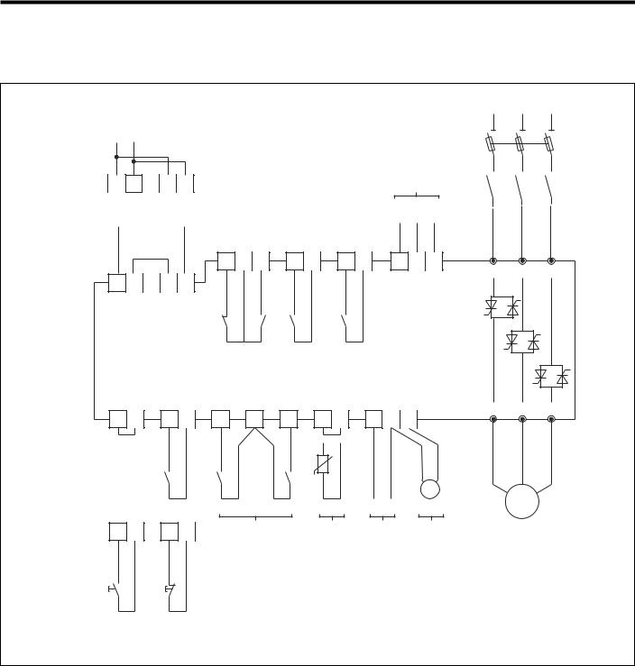
28, 6. Appendix 6-1 6-1. Application diagrams Basic diagram REMARKS: (1) The isolation contactor DC1, is not required to perform operation to the motor. Be aware however that DC1 provides galvanic isolation from the incoming line increasing the safety. (2) In this example, Start and Stop command is enabled by push-buttons. Permanent command is allowed as well, wiri…
-
14, 3. Technical specifications 3-5 Linear acceleration and deceleration ramp Ramp time adjustable (Selectable by parameter «Dxxx» to ON Low slow (7%) and High slow (14%) speeds Enabled by parameter «Jxxx» to ON and «jxxx» to LO or HI Reverse slow speed (20%) Enabled by parameter «Jxxx» to ON and «rxxx» to ON Slow speed (7% or 14%) …
-
6, Increase in productivity and reliability with the use of static soft starters. 1-2. Advantages of the ASTAT Plus Solid State Soft starter 1 Starting and stopping the motor without steps or transitions lengthens the life of power-driven machine mechanical elements, greatly reducing stress on trans- mission and coupling parts. Consequently, overhauling times are reduced and machine and fac…
-
25, GE ASTAT Plus 5-2. Fuses, contactors and supply wiring In Total Fuses Fuses Fuses Control voltage Contactor Contactor Conductor losses aM FERRAZ type BUSSMANN type DC 1 DC 3 section 100% In (F1) (XX=according (Typower Sicu 660V~) Fuse Consumpt. (2) Cat Number A W A mech. design) Size In A VA mm 2 QC _ F DP 17 67 25 6,600 CP URC 14.51/40 00 40 1 18 CL02 CL02 4 QC _ G DP 21 78 32 6,6 …
-
24, GE ASTAT Plus 5-1. Equipment installation CAUTION! DISCONNECT POWER BEFORE INSTALLING OR SERVICING ONLY SPECIALIZED PERSONNEL SHOULD INSTALL THE EQUIPMENT AND ONLY AFTER HAVING READ THIS USER’S GUIDE. THE USER ITSELF IS RESPONSIBLE FOR ANY PHYSICAL INJURY OR MATERIAL DAMAGE RESULTING FROM MISHANDLING THE EQUIPMENT. IF YOU HAVE ANY DOUBTS ABOUT ANY PROCEDURE, PLEASE CONTACT YOUR DEALER. Remarks Supply wire …
-
31, 6. Appendix The following table indicates the communications setting used by Astat Plus to perform data communication via its serial port Name Setting Description Baud Rate 9600 bps Bits per second transmission rate Parity None Data error checking method Data Bits 8 Number of data bits in each transmission Start Bits 1 Number of bits to indicate beginning of transmission Stop Bits 2…
-
12, 3-3. I/O Wiring 3. Technical specifications ASTAT Plus’s terminal layout and wiring configuration is shown in the diagram of below (1*) (1*) (3*) (2*) Notes: (1*) Control and Mains wiring recommendations are given in chapter 5. (2*) The programmable inputs I3, I4 are not assigned to any function as default. Check pages 3-6 prior to using these inputs. (3*) The programmable relay o…
-
30, GE ASTAT Plus 6. Appendix 6-3 6-1. Application diagrams Basic diagram with Linear ramp REMARKS: (1) The isolation contactor DC1, is not required to perform operation to the motor. Be aware however that DC1 provides galvanic isolation from the incoming line increasing the safety. (2) In this example, Start and Stop command is provided by push-buttons. Permanent command is allowed as well, wiring 1, 2 and 57 t…
-
33, 6. Appendix 6-6 Read Parameters from ASTAT Plus The function code assigned to Read is 3 (3h). The request message from master must contain the following information: — Slave address: the master must indicate which slave has been selected. The non-addressed slaves will receive the message but will not execute the command. Only the slave with the corres…
GE ASTAT Plus Recommended Instructions:
E2040T-PN, LA-3A, ALNICO Celestion Gold, AV-16N7, W5340X0GB, H150FD


-
Baumer
SensControl
Wireless IO‑Link Master − innovative way of working with IO‑LinkSimply operate, congure and present your IO‑Link devices with your tabletBenet from the convenient and clearly structured appWork mobile thanks to integrated WLAN, Bluetooth Smart and built‑in battery …
SensControl 10
-
RKC INSTRUMENT
CB103
®RKC INSTRUMENT INC.All Rights Reserved, Copyright © 1999, RKC INSTRUMENT INC. Digital Controller CB103/CB403/CB903 INSTRUCTION MANUAL IMCB11-E7 Thank you for purchasing this RKC product. In order to achieve maximum performance and ensure proper operation of your new instrument, carefully read all the instructions in this manual. Please place the manual in a convenient location for easy referenc …
CB103 8
-
Crestron
3 Series
DO GUIDEDO Install the DeviceThe MC3 is designed to be placed onto a at surface. DO Make ConnectionsMake the necessary connections as called out in the diagrams below. Connect power last.When making connections to the MC3, note the following: • Use Crestron® power supplies for Crestron equipment. • The included cable(s) cannot be extended.NOTE: Ensu …
3 Series 2
-
Berker
KNX-RF
1 6T 7978-30a6T 7978-30aBest.-Nr./Order no./Nr. ord. 8527 51 00Berker GmbH & Co. KGKlagebach 3858579 Schalksmühle/GermanyTelefon: + 49 (0) 23 55/90 5-0Telefax: + 49 (0) 23 55/90 5-111www.berker.com05/201297-85275-100D§¶BedienungsanleitungOperation instructionsIstruzioni per l’usoKNX-Funk Jalousieaktor1fach/Binäreingang 2fach UPKNX-RF blind actuator 1 gang/binary input 2 …
KNX-RF 2
-
Traxxas
XL-5
Thank you for purchasing the Traxxas XL-5 electronic speed control. The XL-5 delivers smooth, precise, full-proportional control over your speed in forward and reverse, combined with powerful and intuitive full-range braking control. The XL-5 comes with the peace-of-mind of the Traxxas Lifetime Electronics Warranty and unmatched Traxxas customer support. The XL-5 is not a toy. I …
XL-5 4
-
Regin
RVAN18-24
INSTRUCTION iRead this instruction before installation and wiring of the productRVAN18-24Valve actuator for 3-point controlRVAN18-24 is a valve actuator designed for control of Regin valves. For more info, see the product sheet of each valve. The actuator can also be combined with other brands of valves using adapter kits. The actuator can be operated manually.Technical dataSupply volt …
RVAN18-24 4
-
Siemens
6ES7134-4FB51-0AB0
SIMATIC ET 200S distributed I/O 2AI U HS analog electronic module (6ES7134-4FB51-0AB0) ______________________________________________________________________ Preface Properties 1Parameters 2Diagnostics 3Analog value representation 4Connecting 5SIMATIC ET 200S distributed I/O2AI U HS analog electronic module (6ES7134-4FB51-0AB0) Manual 04/2007 A5E01076015-01 …
6ES7134-4FB51-0AB0 24
Popular Right Now:
Operating Impressions, Questions and Answers:
Table of Contents for GE ASTAT Plus:
-
3-3. I/O Wiring 3. Technical specifications ASTAT Plus’s terminal layout and wiring configuration is shown in the diagram of below (1*) (1*) (3*) (2*) Notes: (1*) Control and Mains wiring recommendations are given in chapter 5. (2*) The programmable inputs I3, I4 are not assigned to any function as default. Check pages 3-6 prior to using these inputs. (3*) The programmable relay outputs are assigned to the following functions as default: Relay (1r): RUN, (RUN status) Rela
-
4. Programming Ramp up time Ramp down time Kick Start DC Brake time DC Brake current Soft Stop switch Pump Control switch Kick Start Switch Override Switch By-pass Switch DC Brake Switch Lock-out E2PROM Reading Factory Settings Retry Retry time Undervoltage Undervoltage trip time Overvoltage Overvoltage trip time Undercurrent Undercurrent trip time Overcurrent Overcurrent trip time Secondary Ramp up Secondary Ramp down Secondary Starting Torque Tacho control switch Slow Speed switch Low / High slow speeds Reverse slow speed Du
-
6. Appendix 6-3 6-1. Application diagrams Basic diagram with Linear ramp REMARKS: (1) The isolation contactor DC1, is not required to perform operation to the motor. Be aware however that DC1 provides galvanic isolation from the incoming line increasing the safety. (2) In this example, Start and Stop command is provided by push-buttons. Permanent command is allowed as well, wiring 1, 2 and 57 terminals as shown in page 3-3. (3) The output relays allow for direct action on contactors a
-
Section 1. Generalities ……………………………………………………………………………………………………. 1-1 1-1 Comparison of starting systems …………………………………………………………………………….. 1-1 1-2 Advantages of the ASTAT Plus Solid State Soft Starters ……………………………………………. 1-2 Section 2. Types and Ratings …………..
-
Parameter Parameter Function Read/Write Range Comments number name (R/W) 0 Status Soft starter status R/- 0 — 14 0: ON 1: STOP 2: LOCK 3: Alarm (errors) 4: PULS 5: RAMP 6: FULL 7: SAVE 8: SOFT 9: DCBK 10: FULL (override) 11: Not used 12: INCH 13: TACH 14: PUMP 1 M Motor current R/- (%N or Amps, depending on UF parameter) 2 N Nominal motor current (% Unit current) R/W 40-120 3 L Limit current (% In) R/W 100-700 4 T Starting
-
6. Appendix 6-2-4. Profibus/ DeviceNet It is possible to connect Astat Plus to an industrial fieldbus system. Only a communications adapter is required. It is also necessary to set XP to 2. 2 different modules are available: Profibus DP and DeviceNet. Profibus DP: Cat. Nr.: QCPPDP Ordering Nr.: 129769 DeviceNet:: Cat. Nr.: QCPDNT Ordering Nr.: 129768 Detailed information about these communications adapter is des
-
HEAVY DUTY LIGHT DUTY Degree of TYPE Weight Cooled Current 220V / 380V / 440V 480V / Current 220V / 380V / 440V 480V / protection unit rating (2) 240V 415V 500V rating (3) 240V 415V 500V A kW(4) kW(4) kW(4) kW(4) A kW(5) kW(5) kW(5) kW(5) Kg. Lbs. 14 3 5.5 7.5 — 17 4 7.5 7.5 — IP-00 QC1FDP 4.3 9.48 Natural 3 5.5 7.5 7.5 4 7.5 7.5 11 IP-00 QC2FDP 4.3 9.48 Natural 17 4 7.5 7.5 — 21 5.5 11 11 — IP-00 QC1GDP 4.3 9.48 Natural 4 7.5 7.5 11 5.5 11 11 13 IP-
-
4. Programming 4-7 Programmable Basic Functions (follow from previous page) By-pass selector DC Brake selector z xxx B xxx z OF F B OF F This function provides control of an external by-pass contactor, significantly lowering heating losses and eliminating harmonics. When the By-Pass function z is enabled, the programmable relay output 2r is automatically assigned to this function, and must be used to control the external by-pass contactor Enables or disables the DC brake funct
-
Programmable Inputs and functions 3. Technical specifications The ASTAT Plus functions like Soft stop, kick start, and etc, can be enabled or disabled by setting ON or OFF in their dedicated parameters, using the facilities provided by the keypad. Most of these functions can be enabled or disabled remotely as well, through the programmable inputs I3 or I4 (terminals board 3-57 and 4-57). Soft Stop Pump Control Kick Start Override By-pass DC Brake Linear Ramp (Jog). Slow Speed Reverse Jog Dual motor Remote Cont
-
6. Appendix 6-2 6-1. Application diagrams Basic diagram with jog (slow speed) function REMARKS: (1) The isolation contactor DC1, is not required to perform operation to the motor. Be aware however that DC1 provides galvanic isolation from the incoming line increasing the safety. (2) In this example, Start and Stop command is enabled by push-buttons. Permanent command is allowed as well, wiring 1, 2 and 57 terminals as shown in page 3-3. (3) The
-
6. Appendix 6-1 6-1. Application diagrams Basic diagram REMARKS: (1) The isolation contactor DC1, is not required to perform operation to the motor. Be aware however that DC1 provides galvanic isolation from the incoming line increasing the safety. (2) In this example, Start and Stop command is enabled by push-buttons. Permanent command is allowed as well, wiring 1, 2 and 57 terminals as shown in page 3- 3. (3) The output relays allow for direct action on contactors according ratings specified in page 3-2 of this manual. (4) The ASTAT Plus is provided
-
Voltage Ratings 3ph AC Systems Up to 440V, +10%, -15% for QC1xDP ASTAT Plus series Up to 500V, +10%, -15% for QC2xDP ASTAT Plus series Freq. Range 50/60 Hz Control range of 45-65 Hz Control Control system Digital system with microcontroller Specifications Starting ramp with progressive increase in voltage and current limitation Initial voltage (pedestal) % 30 — 95 Un Starting torque % 10 — 90 M direct start Kick start
-
4-1. Keypad and Display description 1 2 Display 1 F VVV F V V V Error code E010 Frequency out of range E011 Overload trip E013 Loss of synchronism E014 Phase U scr E015 Phase V scr E016 Phase W scr E017 Heatsink overtemperature E018 Motor thermistor E019 Phase U lost E020 Phase V lost E021 Phase W lost E022 Stalled rotor E023 Internal error E025 Long start time E026 Long slow speed time E027 Lock-out E028 Undervoltage E029 Overvoltage E030 Undercurrent E031 Overcurrent E032 Retry, attempts exceeded F V V V Sta
-
6. Appendix The following table indicates the communications setting used by Astat Plus to perform data communication via its serial port Name Setting Description Baud Rate 9600 bps Bits per second transmission rate Parity None Data error checking method Data Bits 8 Number of data bits in each transmission Start Bits 1 Number of bits to indicate beginning of transmission Stop Bits 2 Number of bits to indicate ending of transmission Data ASCII / RTU Communications protocol used Handshaking None No need to request to sen
-
2-3. ASTAT Plus, Thermal characteristics The ASTAT Plus allows motor protection according IEC Class 10 or Class 20 and Nema 10, 20 or 30, free selectable by parameter «o» -overload- ASTAT-C / CD . Static soft starters 2. Types and ratings 2-3 IEC Class 10 IEC Class 20 Nema 10 Nema 20 Nema 30 Thermal memory: If the control voltage is not removed, the unit has a cool down charac- teristic, the time for cool down is 300 sec. after the overload trip. If the control voltage is remo
-
6. Appendix The response from the Astat Plus will contain the same slave address and function code, but the data field will include the total number of chars read, and the value of the requested parameters. Quiet Time Slave Address Function Code Data Field CRC Quit Time #of chars 3.5 chars slave# 17 parameters read 2 chars 3.5 chars . Examples Supposing we are trying to communicate with slave 17 (note that 17 is 11h): — To read parameters 3, 4, 5 and 6 Quiet Time Slave Address
Questions, Opinions and Exploitation Impressions:
You can ask a question, express your opinion or share our experience of GE ASTAT Plus device using right now.
![]()
DEH-40397B
GE Industrial Systems
SOLID-STATE SOFT STARTER
ASTAT®-CD Plus
USER MANUAL
REMARKS:
1.Read this manual thoroughly before using the ASTAT-CD Plus and store in a safe place for reference.
2.Make sure that this manual is delivered to the end user.
3.CE Marking
When using ASTAT-CD Plus in the EU, compliance with EMC is required.
All ASTAT-CD Plus sizes comply with the generic EN 50081-2 and EN 50082-2
4.The policy of GE Industrial Systems is one of continuous improvement.
The right is reserved to alter the design on any structural details of the products at any time without giving notice.

ASTAT® -CD Plus Soft Starters
WARNINGS
1.Disconnect power before installing or servicing.
2.Hazardous voltages are present in the motor circuit even when the starter is OFF. An isolation contactor configured to provide automatic isolation when the motor is turned OFF is recommended.
3.Unit may contain more than one live circuit. Disconnect both control and main circuits before installing or servicing.
4.Soft stop should not be used as an Emergency stop.
5.Stopping mode must be set to meet applicable standards for operator safety.
6.Separate motor overcurrent protection is required to be provided in accordance with the
Canadian Electrical Code, Part 1. ASTAT-CD Plus provides separate motor protection.
CAUTIONS
1.Semi-conductor fuses specified may not provide branch circuit protection. Refer to local applicable electrical codes.
2.Overload relay setting should be properly coordinated with motor.
3.Slow speed running will affect the motor thermal characteristic due to reduced cooling.
Care must be taken when operating motor under these conditions.
4DC braking — braking current may cause motor overheating. Select the lowest braking current and time.
5.DC braking must use additional (DC3) in the motor circuit. See wiring diagram page 6-1.
6.Abnormal starting times in excess of 30 seconds, or closely repeated operations of acceleration ramp/deceleration ramp, slow speed, or DC injection braking may cause motor damage. Contact motor manufacturer to ensure proper motor selection has been made for these conditions.
7.If control power is lost between starts, the overload relay protection is reset to cold start conditions.

ASTAT® -CD Plus Soft Starters
PRECAUTIONS
1.Debranchez l’alimentation en courant électrique avant de raccorder ou d’intervenir.
2.Des tensions dangereuses sort présente dans le circuit moteur même si le soft starter indique la position «arrêt». Un contacteur d’isolement assurant un isolement automatique quand le moteur est arrête, est recommendé.
3.L’appareilpeutrenfermer plus d’un circuit sous tension de’brancher les circuitsprincipaux et les circuits de controle avant de raccorder ou d’intervenir.
4.Délestage «soft stop» ne devrait jamais être utilisé en lieu de délestage d’urgence.
5.Procédés de délestage doivent être conforme aux normes de sécurité des utilisateurs.
AVERTISSEMENTS
1.Les fusibles semi-conducteurs specifies ne protégent pas obligatoirement les circuits se conformer aux codes locaux d’installations électriques.
2.Le relais de courant de surcharge doit être proprement coordonné avec la marche du moteur.
3.La marche en sous-régime agira sur les caracteristiques thermiques à cause de la réduction de refroidessement. Opérez le moteur avec précaution dans en ce cas.
4.Ralentissement courant continu peut provoquer la surchauffe de moteur. Choisissez le plus foible courant de décéleration et la durée de ralentissement la plus courte.
5.Pour freinage courant continu, un contacteur (DC3) additional est nécessaire dans le circuit moteur, voir le schéma de raccordement page 6-1.
6.Les délais anormaux de mise en service d’une durée supérieure à 30 secondes, ainsi que les montées/descentes en regime, les exploitations régime lent ou les freinages par injection de courant continu répétés et rapportes sont suseptibles d’edommager le moteur. Mettez-vous en rapport avec votre fabricant en ce qui concerne le choix du moteur adéquat.
7.En cas d’interruption de l’alimentation entre deux dèmarrages, la protection assurée par démarrage à froid.
8.Le moteur doit être muni d’une protection distincte contre les surintensites, et la surchauffe conformement au code de l’electricite, premiere partie. ASTAT-CD Plus le relais de courant de surcharge doit être proprement coordonne avec la marche du moteur.

INDEX
|
Section 1. Overview ………………………………………………………………………………………………………… |
1-1 |
|
|
1-1 |
Applications ……………………………………………………………………………………………………….. |
1-1 |
|
1-2 |
Features and benefits ………………………………………………………………………………………….. |
1-2 |
|
Section 2. Types and Ratings ………………………………………………………………………………………….. |
2-1 |
|
|
2-1 |
IEC Ratings ………………………………………………………………………………………………………… |
2-1 |
|
2-2 |
UL Ratings …………………………………………………………………………………………………………. |
2-2 |
|
2-3 |
Thermal characteristics ………………………………………………………………………………………… |
2-3 |
|
Section 3. Technical Specifications ………………………………………………………………………………… |
3-1 |
|
|
3-1 |
General specifications …………………………………………………………………………………………. |
3-1 |
|
3-2 I/O Terminal board specifications …………………………………………………………………………… |
3-2 |
|
|
3-3 |
I/O wiring ……………………………………………………………………………………………………………. |
3-3 |
|
3-4 |
Operating modes ………………………………………………………………………………………………… |
3-4 |
|
3-5 Programmable inputs and outputs …………………………………………………………………………. |
3-6 |
|
|
Section 4. Programming …………………………………………………………………………………………………. |
4-1 |
|
|
4-1 Keypad and display description …………………………………………………………………………….. |
4-1 |
|
|
4-2 |
Parameter block configuration ………………………………………………………………………………. |
4-2 |
|
4-3 |
Monitor block parameters …………………………………………………………………………………….. |
4-4 |
|
4-4 |
Calibration block parameters ………………………………………………………………………………… |
4-5 |
|
4-5 |
Basic block parameters ……………………………………………………………………………………….. |
4-6 |
|
4-6 |
Advanced block parameters …………………………………………………………………………………. |
4-7 |
|
4-7 Application and basic settings ………………………………………………………………………………. |
4-9 |
|
|
4-8 Saving parameters to E2PROM ……………………………………………………………………………. |
4-9 |
|
|
Section 5. Installation …………………………………………………………………………………………………….. |
5-1 |
|
|
5-1 |
Equipment installation ………………………………………………………………………………………….. |
5-1 |
|
5-2 |
General ……………………………………………………………………………………………………………… |
5-1 |
|
5-3 Fuses, contactors and supply wiring ………………………………………………………………………. |
5-2 |
|
|
5-4 |
Start-up ……………………………………………………………………………………………………………… |
5-3 |
|
5-5 |
Troubleshooting ………………………………………………………………………………………………….. |
5-3 |
|
5-6 |
Thyristor check …………………………………………………………………………………………………… |
5-4 |
|
Section 6. Appendix ……………………………………………………………………………………………………….. |
6-1 |
|
|
6-1 |
Application diagrams …………………………………………………………………………………………… |
6-1 |
|
6-2 |
Serial communications …………………………………………………………………………………………. |
6-4 |
|
6-3 |
Dimensions ………………………………………………………………………………………………………… |
6-9 |
|
6-4 |
PCBs layout ……………………………………………………………………………………………………….. |
6-10 |
i i

1. Overview
1-1. Applications
There are numerous applications where soft starting and limited current peaks are needed for the starting of squirrel cage induction motors. Traditionally reduced voltage starting was accomplished using electromechanical starters such as star delta starters, autotransformer starters, stator resistance starters or by using part winding motors. These methods would provide a two, three or four step torque change by switching the motor voltage from reduced value to full voltage (in steps) after a preset time interval.
ASTAT-CD Plus Solid State Reduced-Voltage Starters (also known as soft starters) use solid state devices to gradually increase the voltage from an initial preset level (initial torque) to full voltage over a selected time period. The same solid state devices may also be used to reduce the voltage for the deceleration of the motor should this be required in the application. This starting and stopping method provides smooth, stepless acceleration and deceleration of AC squirrel-cage induction motors. The ASTAT-CD Plus control circuitry allows many additional functions to be accomplished, such as the monitoring, protection and secondary functions listed.
Versatile Use
ASTAT-CD Plus Solid State Reduced-Voltage Starters offer customer-configurable functions, including pedestal voltage, kick start (selectable), acceleration ramp, current limit, and soft stop (selectable). Typical applications include the following:
|
• Belted equipment |
• Centrifugal fans |
|
• Centrifuges |
• Compressors |
|
• Conveyors |
• Crushers |
|
• Extruders |
• Fans and blowers |
|
• Mixers |
• Packaging equipment |
|
• Pumps |
• Textile machinery |
Advanced Features
The ASTAT-CD Plus incorporates many additional advanced features to insure suitability for most applications.
Monitoring
•Motor Current
•Line Voltage (1)
•Line Power Factor
•Elapsed Time
•Fault History
Protection
•Password
•Lockout
•Undervoltage (1)
•Overvoltage (1)
•Undercurrent
•Overcurrent
•Long Start Time
•Stalled Rotor
Secondary Functions
•Secondary Ramp Up
•Secondary Ramp Down
•Tachometer Feedback
•Dual Motor Switch
•Slow Speed (7&14%)
•Reverse Slow Speed (20%)
•Retry
•DC Injection Braking
•Energy Saving
The ASTAT-CD Plus also features two programmable inputs, three programmable output relays and serial communications control.
Note: (1) Monitors L1
1-1

1. Overview
1-2. Features and benefits
An increase in productivity and reliability with the use of static soft starters.
The ability to start and stop the motor without steps or transitions lengthens the life of power-driven machines’ mechanical parts, and it reduces stress on transmission belts and coupling parts. Consequently, maintenance time is reduced and machine/facility lifespans are lengthened.
Improvement in acceleration / deceleration characteristics
By starting with the voltage ramp or, alternatively, by starting current limitation, the acceleration and deceleration ramp more closely fits the load characteristics. A kick start also may be selected in instances of high static friction load.
Protected motor
The ASTAT-CD Plus protects the motor from overloads and from incorrect operating conditions such as loss of an input or output phase, stalled rotor, thyristor short circuit, etc.
Digital technology
The control system is based upon the use of a highly specialized microcontroller that treats the signals digitally, thereby avoiding deratings and adjustments common to analog circuits. This type of control ensures excellent precision and speed of execution. The control board uses surface-mounted devices (SMD) to increase equipment reliability.
High level of immunity
The control signals are optoelectronically isolated. Various levels of protection have been set up in the circuits to immunize the equipment against external disturbances and their harmful effects.
Easy to run and adjust
The ASTAT-CD Plus can be used for a wide range of applications. A keypad and digital display make it easy to select options that allow the equipment capabilities to be customized to application needs.
Easy maintenance due to full monitoring
Advanced microprocessor technology allows starters to identify 21 different types of fault conditions. The last four errors are retained in memory to facilitate troubleshooting and minimize downtime.
Pump control
The ASTAT-CD Plus includes a pump control function that is more effective in fluid systems than standard soft starting and stopping. The control reduces fluid surges and hammering in a pipeline system. This method controls the motor speed by monitoring the motor parameters with voltage control in a closed-loop system.
Advanced functions
The ASTAT-CD Plus includes advanced functions, such as, linear acceleration ramp, programmable I/O, and connection to a computer by serial communication (RS 232).
1-2

2. Types and Ratings
2-1. IEC Ratings (1)
|
HEAVY DUTY (2) |
LIGHT DUTY |
Degree of |
Cat. No. |
Weight |
Cooled |
|||||||||||||
|
Current |
220V / |
380V / |
440V |
480V / |
Current |
220V / |
380V / |
440V |
480V / |
protection |
||||||||
|
rating |
240V |
415V |
500V |
rating (3) |
240V |
415V |
500V |
|||||||||||
|
A |
kW(4) |
kW(4) |
kW(4) |
kW(4) |
A |
kW(5) |
kW(5) |
kW(5) |
kW(5) |
Kg. |
Lbs. |
|||||||
|
14 |
3 |
5.5 |
7.5 |
— |
17 |
4 |
7.5 |
7.5 |
— |
IP-00 |
QC1FDP |
4.3 |
9.48 |
Natural |
||||
|
3 |
5.5 |
7.5 |
7.5 |
4 |
7.5 |
7.5 |
11 |
IP-00 |
QC2FDP |
4.3 |
9.48 |
Natural |
||||||
|
QC1GDP |
||||||||||||||||||
|
17 |
4 |
7.5 |
7.5 |
— |
21 |
5.5 |
11 |
11 |
— |
IP-00 |
4.3 |
9.48 |
Natural |
|||||
|
4 |
7.5 |
7.5 |
11 |
5.5 |
11 |
11 |
13 |
IP-00 |
QC2GDP |
4.3 |
9.48 |
Natural |
||||||
|
QC1HDP |
||||||||||||||||||
|
22 |
5.5 |
11 |
11 |
— |
27 |
7.5 |
13 |
15 |
— |
IP-00 |
4.6 |
10.14 |
Natural |
|||||
|
5.5 |
11 |
11 |
15 |
7.5 |
13 |
15 |
15 |
IP-00 |
QC2HDP |
4.6 |
10.14 |
Natural |
||||||
|
QC1IDP |
||||||||||||||||||
|
32 |
7.5 |
15 |
18.5 |
— |
38 |
10 |
18.5 |
22 |
— |
IP-00 |
4.6 |
10.14 |
Natural |
|||||
|
7.5 |
15 |
18.5 |
22 |
10 |
18.5 |
22 |
25 |
IP-00 |
QC2IDP |
4.6 |
10.14 |
Natural |
||||||
|
QC1JDP |
||||||||||||||||||
|
48 |
13 |
22 |
22 |
— |
58 |
15 |
25 |
30 |
— |
IP-00 |
12.5 |
27.56 |
By fan |
|||||
|
13 |
22 |
22 |
30 |
15 |
25 |
30 |
37 |
IP-00 |
QC2JDP |
12.5 |
27.56 |
By fan |
||||||
|
QC1KDP |
||||||||||||||||||
|
63 |
15 |
30 |
37 |
— |
75 |
22 |
37 |
45 |
— |
IP-00 |
12.5 |
27.56 |
By fan |
|||||
|
15 |
30 |
37 |
37 |
22 |
37 |
45 |
45 |
IP-00 |
QC2KDP |
12.5 |
27.56 |
By fan |
||||||
|
QC1LDP |
||||||||||||||||||
|
72 |
20 |
37 |
37 |
— |
86 |
25 |
45 |
50 |
— |
IP-00 |
17.0 |
37.48 |
By fan |
|||||
|
20 |
37 |
37 |
45 |
25 |
45 |
50 |
50 |
IP-00 |
QC2LDP |
17.0 |
37.48 |
By fan |
||||||
|
QC1MDP |
||||||||||||||||||
|
105 |
30 |
55 |
55 |
— |
126 |
37 |
63 |
75 |
— |
IP-00 |
17.0 |
37.48 |
By fan |
|||||
|
30 |
55 |
55 |
75 |
37 |
63 |
75 |
80 |
IP-00 |
QC2MDP |
17.0 |
37.48 |
By fan |
||||||
|
QC1NDP |
||||||||||||||||||
|
156 |
40 |
75 |
90 |
— |
187 |
55 |
90 |
110 |
— |
IP-00 |
45.0 |
99.20 |
By fan |
|||||
|
40 |
75 |
90 |
110 |
55 |
90 |
110 |
132 |
IP-00 |
QC2NDP |
45.0 |
99.20 |
By fan |
||||||
|
QC1QDP |
||||||||||||||||||
|
240 |
63 |
110 |
132 |
— |
288 |
80 |
150 |
165 |
— |
IP-00 |
45.0 |
99.20 |
By fan |
|||||
|
63 |
110 |
132 |
160 |
80 |
150 |
165 |
200 |
IP-00 |
QC2QDP |
45.0 |
99.20 |
By fan |
||||||
|
QC1RDP |
||||||||||||||||||
|
315 |
90 |
160 |
200 |
— |
378 |
110 |
200 |
220 |
— |
IP-00 |
55.0 |
121.3 |
By fan |
|||||
|
90 |
160 |
200 |
220 |
110 |
200 |
220 |
250 |
IP-00 |
QC2RDP |
55.0 |
121.3 |
By fan |
||||||
|
QC1SDP |
||||||||||||||||||
|
370 |
110 |
200 |
220 |
— |
444 |
132 |
220 |
250 |
— |
IP-00 |
55.0 |
121.3 |
By fan |
|||||
|
110 |
200 |
220 |
250 |
132 |
220 |
250 |
315 |
IP-00 |
QC2SDP |
55.0 |
121.3 |
By fan |
||||||
|
QC1TDP |
||||||||||||||||||
|
475 |
150 |
250 |
250 |
— |
570 |
160 |
300 |
355 |
— |
IP-00 |
80.0 |
176.4 |
By fan |
|||||
|
150 |
250 |
250 |
335 |
160 |
300 |
355 |
400 |
IP-00 |
QC2TDP |
80.0 |
176.4 |
By fan |
||||||
|
QC1UDP |
||||||||||||||||||
|
610 |
200 |
315 |
400 |
— |
732 |
220 |
400 |
450 |
— |
IP-00 |
105.0 |
231.5 |
By fan |
|||||
|
200 |
315 |
400 |
400 |
220 |
400 |
450 |
500 |
IP-00 |
QC2UDP |
105.0 |
231.5 |
By fan |
||||||
|
QC1VDP |
||||||||||||||||||
|
850 |
250 |
450 |
530 |
— |
1020 |
300 |
560 |
600 |
— |
IP-00 |
120.0 |
264.5 |
By fan |
|||||
|
250 |
450 |
530 |
600 |
300 |
560 |
600 |
750 |
IP-00 |
QC2VDP |
120.0 |
264.5 |
By fan |
||||||
|
QC1XDP |
||||||||||||||||||
|
1075 |
355 |
600 |
670 |
— |
1290 |
395 |
715 |
750 |
— |
IP-00 |
150.0 |
330.7 |
By fan |
|||||
|
355 |
600 |
670 |
750 |
395 |
715 |
750 |
850 |
IP-00 |
QC2XDP |
150.0 |
330.7 |
By fan |
||||||
|
Notes: |
(1) = |
Ratings in Amps. given for ambient temperature up to 40°C and 1000m altitude. |
||||||||||||||||
|
Derate output current by 1.5% / °C above 40°C. |
Derate output current by 1% / 100m above 1000m.
(2)= Heavy duty ratings, IEC Class 10 and 20 protections allowed.
(3)= Light duty ratings, only IEC Class 10 protection allowed.
(4)= Maximum recommended Motor Power for IEC Class 20 protection. Set ASTAT-CD Plus’s parameters «N» and «o» accordingly.
(5)= Maximum recommended Motor Power for IEC Class 10 protection. Set ASTAT-CD Plus’s parameters «N» and «o» accordingly.
2-1

2. Types and Ratings
2-2. UL Ratings (1)
|
Current |
Max. |
HEAVY DUTY |
STANDARD DUTY |
Degree of |
Cat. No. |
Weight |
Cooled |
||||||||||
|
rating |
starting |
200V |
230V |
460V |
200V |
230V |
460V |
protection |
|||||||||
|
current |
|||||||||||||||||
|
A |
A |
HP |
HP |
HP |
HP |
HP |
HP |
Kg. |
Lbs. |
||||||||
|
14 |
63 |
3 |
3 |
7.5 |
3 |
3 |
7.5 |
IP-00 |
QC2FDP |
4.3 |
9.48 |
Natural |
|||||
|
QC2GDP |
|||||||||||||||||
|
17 |
77 |
3 |
3 |
10 |
3 |
3 |
10 |
IP-00 |
4.3 |
9.48 |
Natural |
||||||
|
QC2HDP |
|||||||||||||||||
|
22 |
99 |
5 |
7.5 |
15 |
5 |
7.5 |
15 |
IP-00 |
4.6 |
10.14 |
Natural |
||||||
|
QC2IDP |
|||||||||||||||||
|
34 |
153 |
7.5 |
7.5 |
20 |
10 |
10 |
25 |
IP-00 |
4.6 |
10.14 |
Natural |
||||||
|
QC2JDP |
|||||||||||||||||
|
48 |
216 |
10 |
15 |
30 |
15 |
15 |
30 |
IP-00 |
12.5 |
27.56 |
By fan |
||||||
|
QC2KDP |
|||||||||||||||||
|
63 |
284 |
15 |
20 |
40 |
20 |
20 |
40 |
IP-00 |
12.5 |
27.56 |
By fan |
||||||
|
QC2LDP |
|||||||||||||||||
|
72 |
324 |
20 |
20 |
40 |
20 |
25 |
50 |
IP-00 |
17.0 |
37.48 |
By fan |
||||||
|
QC2MDP |
|||||||||||||||||
|
105 |
473 |
30 |
30 |
60 |
30 |
30 |
75 |
IP-00 |
17.0 |
37.48 |
By fan |
||||||
|
QC2NDP |
|||||||||||||||||
|
156 |
702 |
40 |
50 |
100 |
50 |
60 |
125 |
IP-00 |
45.0 |
99.20 |
By fan |
||||||
|
QC2QDP |
|||||||||||||||||
|
240 |
1080 |
60 |
75 |
150 |
75 |
75 |
200 |
IP-00 |
45.0 |
99.20 |
By fan |
||||||
|
QC2RDP |
|||||||||||||||||
|
315 |
1418 |
75 |
100 |
200 |
100 |
125 |
250 |
IP-00 |
55.0 |
121.25 |
By fan |
||||||
|
QC2SDP |
|||||||||||||||||
|
370 |
1665 |
100 |
125 |
250 |
125 |
150 |
300 |
IP-00 |
55.0 |
121.25 |
By fan |
||||||
|
QC2TDP |
|||||||||||||||||
|
500 |
2250 |
150 |
150 |
350 |
150 |
200 |
400 |
IP-00 |
80.0 |
176.36 |
By fan |
||||||
|
QC2UDP |
|||||||||||||||||
|
630 |
2835 |
200 |
200 |
400 |
200 |
250 |
500 |
IP-00 |
105.0 |
231.47 |
By fan |
||||||
|
QC2VDP |
|||||||||||||||||
|
850 |
3825 |
250 |
300 |
600 |
300 |
350 |
700 |
IP-00 |
120.0 |
264.54 |
By fan |
||||||
|
Notes: |
(1) = |
Ratings in Amps. given for ambient temperature up to 40°C and 1000m altitude. |
|||||||||||||||
|
Derate output current by 1.5% / °C above 40°C. |
Derate output current by 1% / 100m above 1000m.
2-2

2. Types and Ratings
2-3. ASTAT®-CD Plus, Thermal characteristics
The ASTAT-CD Plus allows the user to select motor protection according to IEC Class 10, 20 and NEMA 10, 20 or 30, selectable by»o» -overload- parameter
IEC Class 10
Sec.
COLD
HOT
Multiples of motor FLA rating In
NEMA 10
Sec.
COLD
HOT
Multiples of motor FLA rating In
NEMA 30
Sec.
COLD
HOT
IEC Class 20
Sec.
COLD
HOT
Multiples of motor FLA rating In
NEMA 20
Sec.
COLD
HOT
Multiples of motor FLA rating In
Thermal memory:
If the control voltage is not removed, the unit has a cool down characteristic. The time for cool down is 300 sec. after the overload trip. If the control voltage is removed after tripping, you must wait at least 2 minutes before the unit can be restarted.
Operations per hour:
Using a cycle T, with starting time of t1, running time of T-2t1 at rated current and OFF time of t1 sec. (minimum), the ASTAT-CD Plus allows the following operations per hour.
|
Starting |
Operations / Hour. |
Operations / Hour |
||||
|
Current |
Starting time t1= 10sec. |
Starting time t1=20 sec. |
||||
|
2 Ir |
180 |
90 |
||||
|
3 Ir |
160 |
60 |
||||
|
4 Ir |
30 |
10 |
Multiples of motor FLA rating In
2-3

3. Technical Specifications
3-1. ASTAT®-CD Plus, General specifications
|
Voltage Ratings |
3ph AC Systems |
Up to 500V, +10%, -15% for QC2xDP ASTAT-CD Plus series |
Abbreviations |
||||
|
I |
Actual measured motor current |
||||||
|
Freq. Range |
50/60 |
Hz |
Control range of 45-65 Hz |
||||
|
Im |
Maximum starting current desired |
||||||
|
Control |
Control system |
Digital system with microcontroller |
In |
Nominal motor nameplate FLA |
|||
|
Specifications |
Starting ramp with progressive increase in voltage and current limitation |
Ir |
ASTAT rated nameplate FLA |
||||
|
Initial voltage (pedestal) |
% |
30 — 95 Un |
L |
Current limit for starting Im/Ir |
|||
|
Starting torque |
% |
10 — 90 Mdirect start |
Lmax |
450/N |
|||
|
Kick start |
% |
95 Un (90% Mdirect start), adjustable 0 to 999 ms |
|||||
|
Mdirect start |
Full voltage starting torque |
||||||
|
Motor unit ratio (N) |
0.4 — 1.2 |
||||||
|
N |
In/Ir |
||||||
|
Current limit (starting) |
1 to 4.5 (Ir/In) Max 7.0 In |
||||||
|
Acceleration ramp time |
s |
1 to 99 (types: standard or linear ramp up) |
SF |
Service factor |
|||
|
Energy savings |
Output voltage reduction according to power factor |
Un |
Full line voltage |
||||
|
Override |
Fixed output voltage permanently equal to supply voltage |
||||||
|
Bypass |
Direct control of a bypass contactor |
||||||
|
Brake time by ramp |
s |
1 to 120 (1 to 99 in secondary ramp) adjustable independently of starting ramp time (types: standard, |
|||||
|
pump control or linear ramp down) |
|||||||
|
DC braking |
0 to 99 s.; 0.0 to 2.5xIn |
||||||
|
Slow speed |
Direct torque: 7% or 14% of nominal speed; reverse torque: 20% of nominal speed |
||||||
|
Retry |
0 to 4 attemps, and 1 to 99 sec. retry time |
||||||
|
Monitoring |
Motor current, line voltage (1), power, power factor and elapsed time |
||||||
|
Running |
External control |
Start — Stop |
|||||
|
Acceleration phase |
Adjustable time |
||||||
|
Permanent phase |
Energy savings / Override choice |
||||||
|
Stop phase |
Power cut-off / Ramp / DC braking/Pump control |
||||||
|
Inputs / Outputs |
Inputs |
4 digital optocoupled. Two fixed (Start , Stop), and 2 programmable (I3, I4) |
|||||
|
1 Analog 0-5VDC for Tachogenerator input feedback |
|||||||
|
Outputs |
3 programmable relays (1r, 2r, 3r) |
||||||
|
1 Analog 0-10VDC output for current metering |
|||||||
|
Protections |
Current limit |
Adjustable from 1 to 4.5 (Ir/In) Max 7.0 In |
|||||
|
Overload |
IEC class 10 and 20 ; NEMA class 10, 20 and 30 all selectable |
||||||
|
Cool-down time after |
|||||||
|
overload trip |
s |
300 for reset |
|||||
|
Loss on input phase |
s |
Trip at 3 |
|||||
|
Thyristor short circuit |
ms |
Trip at 200 |
|||||
|
Heatsink overheating |
ms |
Trip at 200 |
|||||
|
Motor thermistor |
ms |
Trip at 200 if thermistor impedance > response value |
|||||
|
Loss on output phase |
s |
Trip at 3 |
|||||
|
Stalled rotor |
ms |
Trip at 200 |
|||||
|
Supply frequency error |
Hz |
If f < 45 or f > 65, will not start |
|||||
|
Overcurrent |
100 to 150% In; trip time adjustable from 0 to 99 sec. |
||||||
|
Undercurrent |
0 to 99% In; trip time adjustable from 0 to 99 sec. |
||||||
|
Overvoltage (1) |
100 to 130% Un; trip time adjustable from 0 to 99 sec. |
||||||
|
Undervoltage (1) |
0 to 50% Un; trip time adjustable from 0 to 99 sec. |
||||||
|
Error (CPU) |
ms |
60 |
|||||
|
Memory |
4 former errors |
||||||
|
Long start time |
s |
2 x ta (ta = acceleration ramp time) |
|||||
|
Long slow speed time |
s |
120 |
|||||
|
Environmental |
Temperature |
°C |
0 to +55 (derate output current by 1.5% / °C above 40°C) |
||||
|
conditions |
Relative humidity |
% |
95% without condensation |
||||
|
Maximum altitude |
m |
3000 (derate output current by 1% / 100m above 1000m) |
|||||
|
Mounting position |
Vertical |
||||||
|
Protection Degree |
IP00, UL Open |
||||||
|
Standards |
CE, cUL, UL |
CE Conforming IEC 947-4-2; UL, cUL conforming to UL508 |
|||||
|
Conducted & radiated emissions |
Conforming IEC 947 -4-2, Class A |
||||||
|
Electrostatic discharges |
Conforming to IEC 1000-4-2, level 3 |
||||||
|
Radioelectric interference |
Conforming to IEC 1000-4-6, level 3 and to IEC 1000-4-3, level 3 |
||||||
|
Immunity to fast trasients |
Conforming to IEC 1000-4-4, level 3 |
||||||
|
Immunity to Surge Voltage |
Conforming to IEC 1000-4-5, level 3 |
||||||
Note: (1) Monitors L1
3-1
![]()
|
3. Technical Specifications |
||||||||||||||||||||||||
|
3-2. I/O Terminal board specifications |
||||||||||||||||||||||||
|
Power I/O terminals |
||||||||||||||||||||||||
|
Terminal |
Function |
Description |
||||||||||||||||||||||
|
1L1, 3L2, 5L3 |
Mains Input |
3ph input voltage 200-480 volts QC2xxx type |
||||||||||||||||||||||
|
2T1, 4T2, 6T3 |
Motor output |
Output terminals to 3ph AC motor |
||||||||||||||||||||||
|
A1, A2, B1, B2 |
Input Control Voltage |
110/120V AC, +10%, -15% |
220/240V AC, +10%, -15% |
|||||||||||||||||||||
|
Digital Inputs |
||||||||||||||||||||||||
|
Terminal |
Function |
Description |
||||||||||||||||||||||
|
57 |
Common for digital inputs |
This is a common terminal for the digital input terminals specified below. |
||||||||||||||||||||||
|
1 |
Run |
Run order. Command signal may be provided by one NO dry momentary contact to terminals 1 and 57. |
||||||||||||||||||||||
|
2 |
Stop |
Stop order. Command signal may be provided by one NC dry momentary contact to terminals 2 and 57. |
||||||||||||||||||||||
|
NOTE: |
Run/Stop permanent command allows linking 1-57 and using one dry NO contact to 2-57 |
|||||||||||||||||||||||
|
terminals. |
||||||||||||||||||||||||
|
3 |
Programmable input I3 |
These two inputs are programmable. They can be assigned to the following internal functions: |
||||||||||||||||||||||
|
4 |
Programmable input I4 |
|||||||||||||||||||||||
|
-soft stop |
-DC brake |
-Linear ramp |
||||||||||||||||||||||
|
-pump control |
-slow speed control |
-dual ramp selection |
||||||||||||||||||||||
|
-kick start |
-reverse slow speed |
-bypass function |
||||||||||||||||||||||
|
-override |
-local / remote control |
|||||||||||||||||||||||
|
Command signal should be provided by one NC dry contact to terminals 57-3 or terminals 57-4. By switching |
||||||||||||||||||||||||
|
this contact ON / OFF it is possible to enable or disable the assigned function. |
||||||||||||||||||||||||
|
Digital Outputs |
||||||||||||||||||||||||
|
Terminal |
Function |
Description |
||||||||||||||||||||||
|
11, 12, 14 |
Programmable relay 1r |
11-12 = NC, 11-14 = N.O. dry contacts. This relay can be assigned to several internal output functions (p. 3.6). |
||||||||||||||||||||||
|
As default assigned to function RUN |
||||||||||||||||||||||||
|
23, 24 |
Programmable relay 2r |
23-24 = N.O. dry contact. This relay can be assigned to several internal output functions (page 3-6). |
||||||||||||||||||||||
|
As default assigned to function EOR |
||||||||||||||||||||||||
|
33, 34 |
Programmable relay 3r |
33-34 = N.O. dry contact. This relay can be assigned to several internal output functions (page 3-6). |
||||||||||||||||||||||
|
As default assigned to function DC BRAKE |
||||||||||||||||||||||||
|
Common for all relay output contacts |
Maximum usage voltage: |
380VAC (B300-UL) |
||||||||||||||||||||||
|
Thermal current: |
8A |
|||||||||||||||||||||||
|
AC-15 use: |
220V / 3A, 380V / 1A |
|||||||||||||||||||||||
|
DC-15 use: |
30V max/ 3.5A |
|
Analog I/O |
||
|
Terminal |
Function |
Description |
|
8 |
Analog input common (-) |
This is a common terminal for the analog input terminal number 7 and analog output terminal number 9. |
|
7 |
TG feedback input (+) |
0-5V analog input for speed feedback. It should be provided by a DC tacho-generator coupled to the motor. |
|
This speed feedback signal is required when the «linear ramp» function is used. |
||
|
9 |
Current output (+) |
0-10V DC analog Output for current measurement purpose. (1 x Ir = 2V DC output) |
|
Load Impedance 10KΩ or higher. |
||
|
Motor thermistor terminals |
||
|
Terminal |
Function |
Description |
|
5 , 6 |
Motor thermistor input |
This input allows a motor thermistor with a response value from 2.8 to 3.2KΩ , and a reset value from 0.75 to |
|
1KΩ to control motor temperature. |
||
|
When the motor thermistor is not used, a link must be used between terminals 5-6. |
||
|
Communications |
||
|
Terminal |
Function |
Description |
|
TD, RD, SG |
Tx, Rx, Gr data |
RS232C, 3 wires, half duplex. Maximum cable length 3meters (10 feet). |
|
Asynchronous data transmission, 9600 Bauds, 1 bit start, 8 bits data, 2 bits stop, no parity. |
||
3-2
3. Technical Specifications
3-3. I/O wiring
ASTAT-CD Plus terminal layout and wiring configuration is shown in the diagram below
|
L1 |
L2 |
L3 |
|||||||||||
|
Control Voltage |
(1*) |
||||||||||||
|
110 / 120V AC |
|||||||||||||
|
A1 A2 |
B1 B2 |
Serial Comm. |
(1*) |
||||||||||
|
RS232C |
|||||||||||||
|
Control Voltage |
Tx |
Rx Gr |
|||||||||||
|
220 / 240V AC |
|||||||||||||
|
12 11 14 |
23 24 |
33 34 |
TD RD SG |
3 L2 |
5 L3 |
||||||||
|
A1 A2 |
B1 B2 |
1 L1 |
|||||||||||
|
1r |
2r |
3r |
|||||||||||
|
Programmable Relay Outputs (3*) |
|||||||||||||
|
Programmable Inputs (2*) |
|||||||||||||
|
I3 |
I4 |
2 T1 |
4 T2 |
6 T3 |
|||||||||
|
1 57 |
2 57 |
3 |
57 |
4 |
5 |
6 |
7 |
8 |
9 |
||||
|
Start /Stop |
— |
+ |
|||||||||||
|
(Permanent Command) |
V |
M |
|||||||||||
|
+ |
— |
||||||||||||
|
3 ~ |
|||||||||||||
|
1 57 |
2 57 |
Programmable Inputs |
MotorThermistor |
Input |
Tacho feedback |
Analog Input |
0-10V |
Analog Output |
|||||
|
(4*) |
|||||||||||||
|
Start |
Stop |
||||||||||||
|
(Command by push-buttons) |
|||||||||||||
|
(4*) |
|
Notes: |
(1) Control and Mains wiring recommendations are given in chapter 5. |
(2)The programmable inputs I3, I4 are not assigned to any function as default. Check pages 3-6 prior to using these inputs.
(3)The programmable relay outputs are assigned to the following functions as default:
Relay (1r): RUN, (RUN status)
Relay (2r): EOR, (End of Ramp)
Relay (3r): DCBR, (DC Braking control)
(4)Important: Use dry contacts only
3-3
 Loading…