
DESCRIPTION
INSPECTION PROCEDURE
READ VALUE USING INTELLIGENT TESTER (ACCUMULATOR SENSOR)
READ VALUE USING INTELLIGENT TESTER (MASTER CYLINDER SENSOR)
RECONFIRM DTC
DTC C1254/54 Pressure Switch Circuit
Description
The accumulator pressure sensor is connected to the skid control ECU in the master cylinder solenoid.

| DTC Code | DTC Detection Condition | Trouble Area |
| C1254/54 | There is an accumulator pressure sensor malfunction (the fluid pressure does not change when the pump operates or when the brake is applied). |
|
Inspection procedure
NOTICE:
When replacing the master cylinder solenoid, perform zero point calibration .
1.READ VALUE USING INTELLIGENT TESTER (ACCUMULATOR SENSOR)
-
Turn the ignition switch off.
-
Connect the intelligent tester to the DLC3.
-
Depress the brake pedal more than 20 times.
-
Turn the ignition switch to ON and turn the intelligent tester on.
-
Enter the following menus: Chassis / ABS/VSC/TRC / Data List.
ABS/VSC/TRC
Tester Display Measurement Item/Range Normal Condition Diagnostic Note Accumulator Sensor Accumulator pressure sensor reading / min.: 0.00 V, max.: 5.00 V 3.58 to 5 V If the value is constant regardless of the pump operation, an accumulator pressure sensor malfunction is suspected.
-
Check the accumulator output value.
Result
Result Proceed to Output value is within the «Normal Condition» range A Output value is out of the «Normal Condition» range LHD B Output value is constant regardless of pump operation LHD Output value is out of the «Normal Condition» range RHD C Output value is constant regardless of pump operation RHD
|
REPLACE MASTER CYLINDER SOLENOID |
|
|
REPLACE MASTER CYLINDER SOLENOID |
|
2.READ VALUE USING INTELLIGENT TESTER (MASTER CYLINDER SENSOR)
-
Turn the ignition switch off.
-
Depress the brake pedal more than 20 times.
-
Install the brake pedal effort gauge (SST), and bleed air.
SST
09709-29018
-
Turn the ignition switch to ON and turn the intelligent tester on.
-
Enter the following menus: Chassis / ABS/VSC/TRC / Data List.
ABS/VSC/TRC
Tester Display Measurement Item/Range Normal Condition Diagnostic Note Master Cylinder Sensor Master cylinder pressure sensor reading / min.: 0.00 V, max.: 5.00 V 0.3 to 1.8 V With pedal effort of 49 N (5 kgf, 11 in.*lbf) The front brake pressure is 930 to 2130 kPa (9.5 to 21.7 kgf/cm2, 135 to 309 psi).
-
Check that the master cylinder pressure sensor output value is normal.
OK:
Master cylinder pressure sensor value is normal.
Result
Result Proceed to OK A NG LHD B RHD C
|
REPLACE MASTER CYLINDER SOLENOID |
|
|
REPLACE MASTER CYLINDER SOLENOID |
|
-
Clear the DTC .
-
Turn the ignition switch off.
-
Depress the brake pedal more than 20 times.
-
Turn the ignition switch to ON.
-
Wait until the pump motor stops.
-
Depress the brake pedal and release it.
-
Wait for 25 minutes.
-
Check if the same DTC is output .
Result
Result Proceed to DTC is not output A DTC is output LHD B RHD C
|
REPLACE MASTER CYLINDER SOLENOID |
|
|
REPLACE MASTER CYLINDER SOLENOID |
|
| A | |
|
USE SIMULATION METHOD TO CHECK |
Ошибки (коды ошибок) полученные от прибора, сканера требуют правильной интерпретации информации, дабы не тратить время и деньги на замену работающих элементов автомобиля.
Проблема зачастую кроется намного глубже чем кажется на первый взгляд. Это& вызвано теми обстоятельствами, что информационные сообщения содержат, как было выше сказано, косвенную информацию о нарушении работы системы.
Может быть полезным для решения вопроса по устранению неисправности у Toyota Land Cruiser 100:
Неисправный электронный модуль управления тормозом (EBCM). Жгут проводов электронного тормозного модуля (EBCM) открыт или замкнут. Схема электронного модуля управления тормозом (EBCM) плохое электрическое соединение.
Микропроцессор содержит область хранения данных, поддерживает живую память, которая может сохранять соответствующие данные, когда зажигание выключено. Данные Keep Alive Memory (KAM) теряются, если от модуля извлекается заряд батареи или заземление модуля. Область KAM является неотъемлемой частью микропроцессора и не может обслуживаться отдельно.
Расшифровка ошибки C1254/54 у Toyota: Короткое замыкание на GND в цепи пиропатрона преднатяжителя переднего пассажира
Марка:
Toyota
Код:
C1254 54
Определение:
Короткое замыкание на GND в цепи пиропатрона преднатяжителя переднего пассажира
Описание:
Центральный датчик подушки безопасности в сборе получает сигнал короткого замыкания на массу в цепи пиропатрона натяжителя (сторона переднего пассажира) в течение 0,5 секунды.
Причина:
- правый наружный ремень переднего сиденья в сборе (пиропатрон преднатяжителя (со стороны переднего пассажира))
- Центральный датчик подушки безопасности в сборе
- Напольный провод № 2
Тип ошибки:
- Front seat outer belt assembly RH (pretensioner squib (front passenger side))
- Center airbag sensor assembly
- No.2 floor wire
Отсутствует калибровка
Этот подтип используется модулем управления, чтобы указать, что рабочий диапазон и т. д. для датчика или исполнительного механизма должен быть запрограммирован модулю управления, например программированием или обучением.
Опрос: Где ремонтируется Ваш автомобиль? (Кол-во голосов: 1966)
У себя в гараже
У официалов
В гараже у Васи
Чтобы проголосовать, кликните на нужный вариант ответа.Результаты
From english:
Decoding the error C1254/54 from Toyota: Short to GND in Front Passenger Side Pretensioner Squib Circuit
Make:
Toyota
Code:
C1254 54
Definition:
Short to GND in Front Passenger Side Pretensioner Squib Circuit
Description:
The center airbag sensor assembly receives a short circuit to ground signal in the pretensioner squib (front passenger side) circuit for 0.5 seconds.
Cause:
Failure Type:
Missing Calibration
This sub type is used by the control module to indicate that an operational range, etc., for a sensor or actuator must be taught to the control module, e.g. by programming or learning.
Еще ошибки категории
Ошибки автомобилей разных произвродителей
Опрос: Смогли ли диагностировать неисправность? (Кол-во голосов: 315)
Да, лично
Да, с помощью знакомого
Да, у официального дилера
Нет
Чтобы проголосовать, кликните на нужный вариант ответа.Результаты
Расскажите друзьям:
Поставьте рейтинг, для нас это очень важно:
Голосов: 0 чел. Рейтинг: 0 из 5.
Стандартные коды ошибок OBD2:
Опрос: Помог ли Вам наш сайт? (Кол-во голосов: 411)
Чтобы проголосовать, кликните на нужный вариант ответа.Результаты
Последние комментарии:
Спасибо большое за самый полыный список ошибок!…
Ошибки полученные от прибора (сканера) требуют правильной интерпретации полученной от него информации, дабы не тратить время и деньги на замену работающих элементов автомобиля.
Вам может быть полезна информация для устранения неисправности:
Неисправный электронный модуль управления тормозом (EBCM). Жгут проводов электронного тормозного модуля (EBCM) открыт или замкнут. Схема электронного модуля управления тормозом (EBCM) плохое электрическое соединение.
Микропроцессор содержит область хранения данных, поддерживает живую память, которая может сохранять соответствующие данные, когда зажигание выключено. Данные Keep Alive Memory (KAM) теряются, если от модуля извлекается заряд батареи или заземление модуля. Область KAM является неотъемлемой частью микропроцессора и не может обслуживаться отдельно.
DTC
|
DTC
|
DTC
|
DTC
|
DTC
|
DTC
|
DTC
|
DTC
|
для подготовки Нажмите здесь
ОПИСАНИЕ
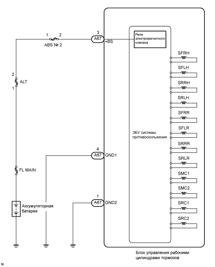
Данные электромагнитные клапаны включены, когда они получают сигналы от ЭБУ системы противоскольжения, и регулируют давление, действующее на рабочие тормозные цилиндры, контролируя тем самым тормозное усилие.
| Код DTC | Условие обнаружения DTC | Неисправный участок |
| C0226/21 C0236/22 C0246/23 C0256/24 C1225/25 C1226/26 C1227/27 C1228/28 |
Сигнал от электромагнитного клапана не соответствует нормальному. |
|
СХЕМА СОЕДИНЕНИЙ
ПОСЛЕДОВАТЕЛЬНОСТЬ ПРОВЕРКИ
- УКАЗАНИЕ:
- Данные коды регистрируются при обнаружении неисправности в блоке управления рабочими цилиндрами тормозов.
- Цепи электромагнитных клапанов находятся в блоке управления рабочими цилиндрами тормозов в сборе.
- Поэтому невозможно выполнить проверку цепи электромагнитного клапана и блока электромагнитного клапана. Перед заменой блока управления рабочими цилиндрами тормозов в сборе обязательно проверьте, не выводятся ли DTC.
-
Сбросьте DTC (Нажмите здесь).
-
Запустите двигатель.
-
Двигайтесь на автомобиле со скоростью не менее 20 км/час (12 миль в час).
-
- Результат:
-
Результат Следующий шаг Коды DTC (C0226/21, C0236/22, C0246/23, C0256/24, C1225/25, C1226/26, C1227/27 и/или C1228/28) не выводятся А Коды DTC (C0226/21, C0236/22, C0246/23, C0256/24, C1225/25, C1226/26, C1227/27 и/или C1228/28) выводятся B
- УКАЗАНИЕ:
- Если при включенном зажигании (IG) и выключенном выключателе стоп-сигналов в ЭБУ системы противоскольжения поступает сигнал скорости 6 км/час (4 мили в час) или более, ЭБУ выполняет самодиагностику цепей двигателя и электромагнитного клапана.
- Если выводится код нормальной работы системы (коды неисправностей не выводятся), слегка покачайте разъемы, жгут проводов и предохранители блока управления рабочими цилиндрами тормозов. Убедитесь, что коды DTC не выводятся.
- Если при покачивании разъема или жгута проводов блока управления рабочими цилиндрами тормозов (ЭБУ системы противоскольжения) выводятся какие-либо коды DTC, проверьте и отремонтируйте разъем или жгут проводов.
- Возможно, коды DTC выводятся вследствие плохого контакта в разъеме.
|
ЗАМЕНИТЕ БЛОК УПРАВЛЕНИЯ РАБОЧИМИ ЦИЛИНДРАМИ ТОРМОЗОВ В СБОРЕ (Нажмите здесь) |
|||
| А | |
|
ПРОВЕРЬТЕ, НЕТ ЛИ ЭПИЗОДИЧЕСКИХ НЕИСПРАВНОСТЕЙ (ИМИТАЦИЯ УСЛОВИЙ ВОЗНИКНОВЕНИЯ НЕИСПРАВНОСТЕЙ) (Нажмите здесь) |
© TOYOTA-COROLLA.RU, 2009-2023
Все права на материал принадлежат:
© 2003 Graham Davies
Battery ECU Diagnostic Trouble Codes
P1600 — Backup power source circuit malfunction
The battery ECU receives 12 volts from two sources. P1600 signifies the absence of 12 volts at terminal AM, which is normally kept live even with the steering wheel switch off.
P3001 — Battery ECU malfunction
P3002 — HV ECU communication malfunction
P3005 — High voltage fuse snapped [sic]
Presumably P3005 would also be recorded if an attempt was made to start up with the service plug removed, as the high voltage fuse is physically located inside the plug.
P3006 — Battery SOC are uneven
P3006 — not too sure about this, but criterion appears to be maximum permitted difference between highest block voltage and lowest block voltage at any instant (not including transients) is 1.2 volts.
P3009 — Leak detected
P3009 — «Leak detected», meaning a current leakage path the high voltage circuitry to the chassis has been detected. Trigger level not known, but the criterion for manual testing is insulation resistance not less than 10M ohms when tested at 500V DC.
P3010 — Battery total resistance malfunction
P3011 to P3029 — Battery block malfunction
The traction battery consists of 38 physical modules, each containing 6 cells. For the purposes of monitoring by the battery ECU, modules are paired into 19 «blocks». DTCs P3011 to P3029 appear to indicate the «malfunction» of a particular block, although what «malfunction» means is not clear.
P3030 — Battery voltage detective line snapped [sic]
P3030 — presumably means open circuit of one of the twenty voltage sense lines which are connected to the cell string at the ends and between each block.
P3060 — Battery temperature sensor circuit malfunction
P3076 — Abnormal air flow by battery cooling fan
P3077 — Battery cooling fan motor circuit malfunction
P3115 — HV battery current sensor malfunction
Braking System Diagnostic Trouble Codes
Two tables have been concatenated. Codes C0200 to C1259 are from the table «DIAGNOSTIC TROUBLE CODE CHART» on pages DI-358 and DI-359, and codes C1271 to C1284 are from the table «DTC of sensor check function» on page DI-357.
C0200 — Right front wheel speed sensor signal malfunction
C0205 — Left front wheel speed sensor signal malfunction
C0210 — Right rear wheel speed sensor signal malfunction
C0215 — Left rear wheel speed sensor signal malfunction
C0226 — Malfunction in ABS solenoid (SFR) circuit
C0236 — Malfunction in ABS solenoid (SFL) circuit
C0246 — Malfunction in ABS solenoid (SR) circuit
C0278 — Open circuit in ABS solenoid relay circuit
C0279 — Short circuit in ABS solenoid relay circuit
C1202 — Brake fluid low, or open circuit in brake fluid level warning switch circuit
C1211 — Malfunction in linear solenoid (SLA) circuit
C1212 — Malfunction in linear solenoid (SLR) circuit
C1213 — Malfunction in HV ECU communication circuit
C1214 — Malfunction in hydraulic system
C1215 — Low positive voltage of linear solenoid
C1216 — High positive voltage of linear solenoid
C1217 — Malfunction in regenerative solenoid (SMC1) circuit
C1218 — Malfunction in regenerative solenoid (SMC2) circuit
C1219 — Malfunction in regenerative solenoid (SS) circuit
C1220 — Malfunction in regulator (REG) pressure sensor
C1221 — Malfunction in front (FR) pressure sensor
C1222 — Malfunction in rear (RR) pressure sensor
C1241 — Low or abnormally high battery positive voltage in IG1 circuit
C1242 — Open circuit in IG2 circuit
C1246 — Malfunction in master cylinder (M/C) pressure sensor
C1249 — Open circuit in stop light switch circuit
C1251 — Malfunction in hydraulic brake booster pump motor
C1252 — Hydraulic brake booster pump motor ON time abnormally long
C1253 — Malfunction in hydro motor relay circuit
C1254 — Malfunction in pressure switch
C1256 — Malfunction of accumulator low pressure
C1257 — Malfunction in power supply drive circuit
C1259 — Malfunction in regenerative of HV ECU
C1271 — Low output voltage of right front speed sensor
C1272 — Low output voltage of left front speed sensor
C1273 — Low output voltage of right rear speed sensor
C1274 — Low output voltage of left rear speed sensor
C1275 — Abnormal change in output voltage of right front speed sensor
C1276 — Abnormal change in output voltage of left front speed sensor
C1277 — Abnormal change in output voltage of right rear speed sensor
C1278 — Abnormal change in output voltage of left rear speed sensor
C1281 — Master cylinder (M/C) pressure sensor output signals is faulty
C1282 — Regulator (REG) pressure sensor output signal is faulty
C1283 — Front (FR) pressure sensor output signal is faulty
C1284 — Rear (RR) pressure sensor output signal is faulty
Engine ECU Diagnostic Trouble Codes
Engine ECU — SAE Controlled
These items are taken from the table «Engine Diagnostics, SAE controlled» on pages DI-14 to DI-16 in the Engine Diagnostics chapter of the Repair Manual.
P0100 — Mass Air Flow Circuit Malfunction
P0101 — Mass Air Flow Circuit Range/Performance Problem
P0110 — Intake Air Temp Circuit Malfunction
P0115 — Engine Coolant Temp. Circuit Malfunction
P0116 — Engine Coolant Temp. Circuit Range/Performance Problem
P0120 — Throttle/Pedal Position Sensor/Switch «A» Circuit Malfunction
P0121 — Throttle/Pedal Position Sensor/Switch «A» Circuit Range/Performance Problem
P0125 — Insufficient Coolant Temp. for Closed Loop Fuel Control
P0128 — Thermostat Malfunction
P0130 — Heated Oxygen Sensor Circuit Malfunction (Bank 1 Sensor 1) (Except Calif.)
P0133 — Oxygen Sensor Circuit Slow Response (Bank 1 Sensor 1)
P0135 — Oxygen Sensor Circuit Malfunction (Bank 1 Sensor 1)
P0136 — Oxygen Sensor Circuit Malfunction (Bank 1 Sensor 2)
P0141 — Oxygen Sensor Heater Circuit Malfunction (Bank 1 Sensor 2)
P0171 — System too Lean (Fuel Trim)
P0172 — System too Rich (Fuel Trim)
P0300 — Random/Multiple Cylinder Misfire Detected
P0301 — Cylinder 1 Misfire Detected
P0302 — Cylinder 2 Misfire Detected
P0303 — Cylinder 3 Misfire Detected
P0304 — Cylinder 4 Misfire Detected
P0325 — Knock Sensor 1 Circuit Malfunction (Bank 1)
P0335 — Crankshaft Position Sensor «A» Circuit Malfunction
P0340 — Camshaft Position Sensor Circuit Malfunction
P0420 — Catalyst System Efficiency Below Threshold (Bank 1)
P0440 — Evaporative Emission Control System Malfunction
This and the following two DTCs can occur if you drive around for a while with a loose fuel filler cap. I did this to test retreiving DTCs with the Prius Mini-Scanner and it took more than a day for the problem to be detected.
P0441 — Evaporative Emission Control System Incorrect Purge Flow
P0446 — Evaporative Emission Control System Vent Control Malfunction
P0450 — Evaporative Emission Control System Pressure Sensor Malfunction
P0451 — Evaporative Emission Control System Pressure Sensor Range/Performance
P0500 — Vehicle Speed Sensor Malfunction
P0505 — Idle Control System Malfunction
Engine ECU — Manufacturer Controlled
These items are taken from the table «Engine Diagnostics, manufacturer controlled» on pages DI-17 and DI-18 in the Engine Diagnostics chapter of the Repair Manual.
P1125 — Throttle Control Motor Circuit Malfunction
P1127 — ETCS Actuator Power Source Circuit Malfunction
P1128 — Throttle Control Motor Lock Malfunction
P1129 — Electric Throttle Control System Malfunction
P1300 — Igniter Circuit Malfunction (No. 1)
P1305 — Igniter Circuit Malfunction (No. 2)
P1310 — Igniter Circuit Malfunction (No. 3)
P1315 — Igniter Circuit Malfunction (No. 4)
P1346 — VVT Sensor/Camshaft Position Sensor Circuit Range/Performance Problem (Bank 1)
P1349 — VVT System Malfunction (Bank 1)
P1430 — Vacuum Sensor for Adsorber and Catalyst System Circuit Malfunction
P1431 — Vacuum Sensor for Adsorber and Catalyst System Circuit Range/Performance Problem
P1436 — Variable Valve Malfunction
P1437 — Vacuum Line Malfunction
P1455 — Vapor Reducing Fuel Tank System Leak Detected (Small Leak)
P1525 — Resolver Circuit Malfunction
P1600 — ECM BATT Malfunction
P1633 — ECU Malfunction (ETCS Circuit)
P1636 — HV ECU Malfunction
P1637 — EGSTP Signal Malfunction
P1656 — OCV Circuit Malfunction (for VVT-i)
P3190 — Poor Engine Power
P3191 — Engine does not start
EMPS Diagnostic Trouble Codes
Two tables have been merged, «DTC of input signal check function» from page DI-457, and «Diagnostic trouble code chart» from DI-460 and DI-461.
C1511 — Torque sensor circuit malfunction
C1512 — Torque sensor circuit malfunction
C1513 — Torque sensor circuit malfunction
C1514 — Torque sensor circuit malfunction
C1515 — Calibration of torque sensor zero point not performed
C1516 — Calibration of torque sensor zero point not completed
C1521 — Motor circuit malfunction
C1522 — Motor circuit malfunction
C1523 — Motor circuit malfunction
C1524 — Motor circuit malfunction
C1531 — EMPS ECU malfunction
C1532 — EMPS ECU malfunction
C1533 — EMPS ECU malfunction
C1541 — Speed sensor malfunction
C1542 — Speed sensor malfunction
C1543 — Speed sensor malfunction
C1551 — IG power source circuit malfunction
C1552 — PIG power source drop voltage malfunction
C1553 — When resetting voltage, vehicle is being driven
C1554 — EMPS relay circuit malfunction
C1555 — EMPS ECU malfunction
C1556 — P/S warning light circuit
C1557 — Memory of overheat prevention control
C1558 — Memory of voltage drop at motor power supply
C1559 — Memory of continuous control under high load
C1571 — Speed sensor malfunction (Test mode)
C1572 — Speed sensor malfunction (Test mode)
Hybrid Vehicle ECU Diagnostic Trouble Codes
In addition to the letter-plus-four-digit DTC, the HV-ECU generates «information codes» consisting of three digits. These give a more finely detailed definition of the problem. They can be retrieved by the THHT (Toyota Hand-Held Tester) but not by a normal OBD-II scanner. How the THHT retrieves information codes has not been determined, therefore they cannot be retrieved by the Prius Mini-Scanner.
From pages DI-199 through to DI-205, in the Hybrid Vehicle Control System chapter of the Repair Manual.
B2799 — Immobilizer Malfunction
101 No input of signal from transponder key ECU
C2692 — Regenerative Brake Check
102 Regenerative Brake Check
C2693 — Regenerative Brake Check
103 Regenerative Brake Check
P1120 — Accelerator Pedal Position Sensor Circuit Malfunction
This DTC has been caught in the wild on an early 2001 model year Prius. The accelerator pedal position sensor is know to cause problems on these cars and there is a TSB out on it.
104 Open or short circuit in main accelerator sensor circuit
105 +B short in main accelerator sensor circuit
106 Main sensor internal error
107 Open or short in sub accelerator sensor circuit
108 +B short in sub accelerator sensor circuit
109 Sub sensor internal error
110 When difference between main sensor value and sub sensor value is large
111 When sub sensor value changes while main sensor value does not
112 When main sensor value changes while sub sensor value does not
113 When any of information code 104-112 continues to appear
114 Accelerator pedal not smoothly returning to original position
P1520 — Stop Light Switch (Cruise Control System) Malfunction
115 Open or short in stop light switch circuit
P1566 — Cruise Control System Malfunction
116 When STP signal of HV ECU is inconsistent with that of brake ECU, with cruise control indicator ON
P1600 — BATT Malfunction
117 HV ECU back-up power source circuit malfunction
P1780 — Park/Neutral Position Switch System Malfunction
118 When more than 2 main signals are ON
119 When main signal is not turned ON even though sub signal has been input
120 Open or short in sub sensor circuit
121 When shift position detected by main signal is different from that detected by sub signal
P3000 — HV Battery Malfunction
123 Input of abnormal signal from battery ECU (HV Battery System Malfunction)
124 Input of abnormal signal from battery ECU (high voltage fuse blown out)
388 Discharge Inhibition Control Malfunction. When charged battery is low due to leaving the vehicle in N position, gas shortage or HV system malfunction
389 Drop of high voltage. When main battery is dead or main battery is dead due to HV system malfunction
P3001 — HV Battery ECU Malfunction
129 Battery ECU malfunction
P3004 — Power Cable Malfunction
130 HV Battery Malfunction. When HV battery voltage becomes lower than inverter voltage
131 Power Cable Malfunction. When main fuse is blown out, service plug is disconnected or limiter resistance is cut off
133 HV Battery Malfunction. When inverter voltage sensor is malfunctioning or limiter resistance value increases
P3100 — HV ECU Malfunction
127 IB Circuit Malfunction. +B short in IB terminal circuit of HV ECU
128 IB Circuit Malfunction. Open or short in IB terminal circuit of HV ECU
134 HV ECU Internal Error
135 HV ECU Internal Error
136 GO Signal Error. Open or short in GO circuit
137 Engine Speed Sensor Malfunction
138 IB Circuit Malfunction. When the difference between current of HV ECU and current of battery is large
139 HV ECU internal error. IG Signal Circuit Malfunction
140 HV ECU internal error. RAM Braked
141 HV ECU internal error. ROM Braked
142 ST Signal Circuit Malfunction. When ST signal of HV ECU is ON, with ignition switch turned OFF
143 HV ECU internal error. Immobilizer Malfunction
144 HV ECU internal error. Primary Check Malfunction
145 HV ECU internal error. Primary Check Malfunction
146 HV ECU internal error. Primary Check Malfunction
147 HV ECU internal error. Primary Check Malfunction
148 HV ECU internal error. HV CPU Malfunction
149 HV ECU internal error. HV CPU Malfunction
150 HV ECU internal error. Motor CPU Malfunction
151 HV ECU internal error. Motor CPU Malfunction
152 HV ECU internal error. Motor CPU Malfunction
153 HV ECU internal error. Motor CPU Malfunction
154 HV ECU internal error. Motor CPU Malfunction
155 HV ECU internal error. Motor CPU Malfunction
156 HV ECU internal error. Motor CPU Malfunction
157 HV ECU internal error. Motor CPU Malfunction
158 HV ECU internal error. Motor CPU Malfunction
159 HV ECU internal error. Motor ECU Communication Circuit Malfunction
160 HV ECU internal error. Motor ECU Communication Circuit Malfunction
161 HV ECU internal error. Motor ECU Power Source Malfunction
162 HV ECU internal error. Motor ECU Power Source Malfunction
163 HV ECU internal error. Motor ECU Power Source Malfunction
164 HV ECU internal error. Motor ECU Power Source Malfunction
165 HV ECU internal error. Motor ECU Power Source Malfunction
166 HV ECU internal error. Motor R/D Malfunction
167 HV ECU internal error. Motor R/D Malfunction
168 HV ECU internal error. Motor R/D Malfunction
169 HV ECU internal error. Motor R/D Malfunction
170 HV ECU internal error. Motor R/D Malfunction
171 HV ECU internal error. Motor REF Signal Malfunction
172 HV ECU internal error. Motor REF Signal Malfunction
173 HV ECU internal error. Motor REF Signal Malfunction
174 HV ECU internal error. Motor Inverter Current Sensor Malfunction
175 HV ECU internal error. Motor Inverter Current Sensor Malfunction
176 HV ECU internal error. Motor Gate Shutdown Signal Line Connection Malfunction
177 HV ECU internal error. Motor Main CPU Malfunction
178 HV ECU internal error. Motor Main CPU Malfunction
179 HV ECU internal error. Motor Main CPU Malfunction
180 HV ECU internal error. Rotation Angle Check CPU Malfunction
181 HV ECU internal error. Rotation Angle Check CPU Malfunction
182 HV ECU internal error. Rotation Angle Check CPU Malfunction
183 HV ECU internal error. Rotation Angle Check CPU Malfunction
184 HV ECU internal error. Rotation Angle Check CPU Malfunction
185 HV ECU internal error. Rotation Angle Check CPU Malfunction
186 HV ECU internal error. Rotation Angle Check CPU Malfunction
187 HV ECU internal error. Important RAM Malfunction
188 HV ECU internal error. Generator CPU Malfunction
189 HV ECU internal error. Generator CPU Malfunction
190 HV ECU internal error. Genarator CPU Malfunction
191 HV ECU internal error. Generator CPU Malfunction
192 HV ECU internal error. Generator CPU Malfunction
193 HV ECU internal error. Generator CPU Malfunction
194 HV ECU internal error. Generator CPU Malfunction
195 HV ECU internal error. Generator CPU Malfunction
196 HV ECU internal error. Generator CPU Malfunction
197 HV ECU internal error. Generator R/D Malfunction
198 HV ECU internal error. Generator R/D Malfunction
199 HV ECU internal error. Generator R/D Malfunction
200 HV ECU internal error. Generator R/D Malfunction
201 HV ECU internal error. Generator R/D Malfunction
202 HV ECU internal error. Generator R/D Malfunction
203 HV ECU internal error. Generator Shutdown Signal Line Connection Malfunction
271 HV ECU internal error. Motor PWN Line Connection Malfunction
310 HV ECU internal error. Generator PWN Line Connection Malfunction
390 HV ECU internal error. Charge Inhibition Control Malfunction
391 HV ECU internal error. Motor CPU malfunction
392 HV ECU internal error. Motor CPU malfunction
393 HV ECU internal error. HV CPU Operation Malfunction
P3101 — Engine System Malfunction
204 Input of abnormal signal from the ECM (abnormal engine output)
205 Input of abnormal signal from the ECM (engine unable to start)
238 Transaxle Malfunction. When engine does not start even though cranking it
P3105 — Battery ECU Communication Circuit Malfunction
206 When communication between battery ECU and HV ECU is abnormal 1 sec. after ignition is turned ON
207 When communication between battery ECU and HV ECU is abnormal 1 sec. after ignition is turned ON
208 When communication between battery ECU and HV ECU is abnormal 1 sec. after ignition is turned ON
P3106 — ECM Communication Circuit Malfunction
209 When communication between ECM and HV ECU is abnormal 1 sec. after ignition is turned ON
210 When communication between ECM and HV ECU is abnormal 1 sec. after ignition is turned ON
211 When communication between ECM and HV ECU is abnormal 1 sec. after ignition is turned ON
212 Input of abnormal signal from ECM
394 When ECM does not operate
P3107 — Airbag ECU Communication Circuit Malfunction
213 When communication between airbag ECU and HV ECU is abnormal 10 sec. after ignition is turned ON
214 When communication between airbag ECU and HV ECU is abnormal 10 sec. after ignition is turned ON
215 When communication between airbag ECU and HV ECU is abnormal 10 sec. after ignition is turned ON
P3108 — A/C Amplifier Communication Circuit Malfunction
216 When communication from A/C amplifier to HV ECU is abnormal
217 When communication from A/C amplifier to HV ECU is abnormal
P3109 — Brake ECU Communication Circuit Malfunction
218 When communication between brake ECU and HV ECU is abnormal 1.5 sec. after ignition is turned ON
219 When communication between brake ECU and HV ECU is abnormal 1.5 sec. after ignition is turned ON
220 When communication between brake ECU and HV ECU is abnormal 1.5 sec. after ignition is turned ON
221 When communication between brake ECU and HV ECU is abnormal 1.5 sec. after ignition is turned ON
222 When abnormal data is received from brake ECU
P3110 — IGCT Relay Malfunction
223 When IGCT relay is always closed
P3115 — System Main Relay Malfunction
224 SMR Cont 1 Malfunction. Open or +B short in system main relay No. 1 circuit
225 SMR Cont 1 Malfunction. Short in system main relay No. 1 circuit
226 SMR Cont 2 Malfunction. Open or +B short in system main relay No. 2 circuit
227 SMR Cont 2 Malfunction. Short in system main relay No. 2 circuit
228 SMR Cont 3 Malfunction. Open or +B short in system main relay No. 3 circuit
229 SMR Cont 3 Malfunction. Short in system main relay No. 3 circuit
231 Deposit of SMR. System main relay + terminal deposited
232 Deposit of SMR. System main relay — terminal deposited
233 Deposit of SMR. System main relay + & — terminal deposited
P3120 — HV Transaxle Malfunction
234 Energy Balance Malfunction. Small reduction of motor magnetism
235 Energy Balance Malfunction. Large reduction of motor magnetism
236 Energy Balance Malfunction. Small reduction of generator magnetism
237 Energy Balance Malfunction. Large reduction of generator magnetism
239 HV Transaxle Malfunction. Shaft damaged
240 HV Transaxle Malfunction. Generator locked
241 HV Transaxle Malfunction. Torque limiter sliding
242 HV Transaxle Malfunction. Planetary gear locked
243 Motor Resolver Malfunction. Motor resolver inter-phase short
244 Motor Resolver Malfunction. Motor resolver inter-phase short (When there is a history that the state of malfunction continued during inverter fail safe mode)
245 Motor Resolver Malfunction. Open or short in motor resolver circuit
246 Motor Resolver Malfunction. Open or short in motor resolver circuit (When there is a history that the state of malfunction continued during inverter fail safe mode)
247 Motor Temperature Sensor Malfunction. GND short in motor temperature sensor
248 Motor Temperature Sensor Malfunction. Motor temperature sensor malfunction
249 Motor Temperature Sensor Malfunction. Open or +B short in motor temperature sensor
250 Motor Temperature Sensor Malfunction. Motor temperature sensor performance problem
253 Generator Resolver Malfunction. Generator resolver inter-phase short
254 Generator Resolver Malfunction. Generator resolver inter-phase short (When there is a history that the state of malfunction continued during inverter fail safe mode)
255 Generator Resolver Malfunction. Open or short in generator resolver circuit
256 Generator Resolver Malfunction. Open or short in generator resolver circuit (When there is a history that the state of malfunction continued during inverter fail safe mode)
257 Generator Temperature Sensor Malfunction. GND short in generator temperature sensor
258 Generator Temperature Sensor Malfunction. Generator temperature sensor malfunction
259 Generator Temperature Sensor Malfunction. Open or +B short in generator temperature sensor
260 Generator Temperature Sensor Malfunction. Generator temperature sensor performance problem
P3125 — Converter & Inverter Assembly Malfunction
263 DC/DC Converter Malfunction. +B short in DCDC converter NODD wiring
264 DC/DC Converter Malfunction. DCDC converter malfunction
265 DC/DC Converter Malfunction. Open or GND short in DCDC converter NODD wiring
266 VM Malfunction. Open or GND short in inverter voltage signal circuit
267 VM Malfunction. +B short in inverter voltage signal circuit
268 VM Malfunction. Inverter voltage signal is inconsistent with battery voltage
269 VM Malfunction. Inverter voltage sensor malfunction
270 VM Malfunction. Abnormality of line connection of inverter foltage signal circuit (When there is a history that the state of malfunction continued during inverter fail safe mode)
272 Motor PWN Line Connection Malfunction. Abnormality of the line connection of motor PWM (When there is a history that the state of malfunction continued during inverter fail safe mode)
273 Motor Inverter Gate Malfunction. Motor inverter malfunction
274 Motor Inverter Temperature. Open or +B short in motor inverter temperature sensor
275 Motor Inverter Temperature. GND short in motor inverter temperature sensor
276 Sensor Malfunction. Motor inverter temperature sensor malfunction
277 Sensor Malfunction. Motor inverter temperature sensor performance problem
278 Motor Inverter Sinv. +B short in motor inverter stop signal circuit
279 Motor Inverter Sinv. Over voltage of inverter
280 Motor Inverter Sinv. Open or GND short in motor inverter stop signal circuit
281 Motor Inverter Sinv. Voltage drop of inverter power source
282 Motor Inverter Sinv. Inverter circuit broken
283 Motor Inverter Finv. +B short in motor inverter fail signal circuit
284 Motor Inverter Finv. Inverter overheating
285 Motor Inverter Finv. Open or GND short in motor inverter fail signal circuit
286 Motor Inverter Finv. Inverter circuit broken
287 Motor Inverter Finv. Inverter internal short
288 Motor Inverter Current Sensor Malfunction. Motor inverter current sensor malfunction (V phase sub sensor)
289 Motor Inverter Current Sensor Malfunction. Open in inverter current sensor (V phase sub sensor)
290 Motor Inverter Current Sensor Malfunction. Motor inverter current sensor malfunction (V phase main sensor)
291 Motor Inverter Current Sensor Malfunction. (when there is a history that the state of malfunction continued during inverter fail safe mode)
292 Motor Inverter Current Sensor Malfunction. Open in motor inverter current sensor (V phase main sensor)
293 Motor Inverter Current Sensor Malfunction.
(when there is a history that the state of malfunction continued during inverter fail safe mode)
294 Motor Inverter Current Sensor Malfunction. Motor inverter current sensor V phase performance problem
295 Motor Inverter Current Sensor Malfunction. (when there is a history that the state of malfunction continued during inverter fail safe mode)
296 Motor Inverter Current Sensor Malfunction. Motor inverter current sensor malfunction (W phase sub sensor)
297 Motor Inverter Current Sensor Malfunction. Open in motor inverter current sensor (W phase sub sensor)
298 Motor Inverter Current Sensor Malfunction. Motor inverter current sensor malfunction (W phase main sensor)
299 Motor Inverter Current Sensor Malfunction. (when there is a history that the state of malfunction continued during inverter fail safe mode)
300 Motor Inverter Current Sensor Malfunction. Open in motor inverter current sensor (W phase main sensor)
301 Motor Inverter Current Sensor Malfunction. (when there is a history that the state of malfunction continued during inverter fail safe mode)
302 Motor Inverter Current Sensor Malfunction. Motor inverter current sensor W phase performance problem
303 Motor Inverter Current Sensor Malfunction. (when there is a history that the state of malfunction continued during inverter fail safe mode)
304 Motor Gate Shutdown Signal Line Connection Malfunction. +B short in motor gate shutdown signal circuit
305 Motor Gate Shutdown Signal Line Connection Malfunction. Open or GND short in motor gate shutdown signal circuit
306 Failure in Monitoring Motor Torque Performance.
307 Abnormal Current Value of Motor
308 Detection of Collision Signal
309 Motor PWM Line Connection Malfunction. Open or short in generator inverter switching wiring (GUU, GVU, GWU)
311 Generator Inverter Malfunction
312 Generator Inverter Temperature Sensor Malfunction. Open or +B short in generator inverter temperature sensor
313 Generator Inverter Temperature Sensor Malfunction. GND short in generator inverter temperature sensor
314 Generator Inverter Temperature Sensor Malfunction. Generator inverter temperature sensor malfunction
315 Generator Inverter Temperature Sensor Malfunction. Generator inverter temperature sensor performance problem
316 Generator Inverter Sinv. +B short in generator inverter stop signal circuit
317 Generator Inverter Sinv. Over voltage of inverter
318 Generator Inverter Sinv. Open or GND short in generator inverter stop signal circuit
319 Generator Inverter Sinv. Voltage drop of inverter power source
320 Generator Inverter Sinv. Inverter circuit broken
321 Generator Inverter Finv. +B short in generator inverter fail signal circuit
322 Generator Inverter Finv. Inverter overheating
323 Generator Inverter Finv. Open or GND short in generator inverter fail signal circuit
324 Generator Inverter Finv. Inverter circuit broken
325 Generator Inverter Finv. Inverter internal short
326 Generator Inverter Current Sensor Malfunction. Generator inverter current sensor malfunction (V phase sub sensor)
327 Generator Inverter Current Sensor Malfunction. Open in generator inverter current sensor (V phase sub sensor)
328 Generator Inverter Current Sensor Malfunction. Generator inverter current sensor malfunction (V phase main sensor)
329 Generator Inverter Current Sensor Malfunction. (when there is a history that the state of malfunction continued during inverter fail safe mode)
330 Generator Inverter Current Sensor Malfunction. Open in generator inverter current sensor (V phase main sensor)
331 Generator Inverter Current Sensor Malfunction. (when there is a history that the state of malfunction continued during inverter fail safe mode)
332 Generator Inverter Current Sensor Malfunction. Generator inverter current sensor V phase performance problem
333 Generator Inverter Current Sensor Malfunction. (when there is a history that the state of malfunction continued during inverter fail safe mode)
334 Generator Inverter Current Sensor Malfunction. Generator inverter current sensor malfunction (W phase sub sensor)
335 Generator Inverter Current Sensor Malfunction. Open in generator inverter current sensor (W phase sub sensor)
336 Generator Inverter Current Sensor Malfunction. Generator inverter current sensor malfunction (W phase main sensor)
337 Generator Inverter Current Sensor Malfunction. (when there is a history that the state of malfunction continued during inverter fail safe mode)
338 Generator Inverter Current Sensor Malfunction. Open in generator inverter current sensor (W phase main sensor)
339 Generator Inverter Current Sensor Malfunction. (when there is a history that the state of malfunction continued during inverter fail safe mode)
340 Generator Inverter Current Sensor Malfunction. Generator inverter current sensor W phase performance problem
341 Generator Inverter Current Sensor Malfunction. (when there is a history that the state of malfunction continued during inverter fail safe mode)
342 Motor Gate Shutdown Signal Line Connection. +B short in generator gate shutdown signal
343 Motor Gate Shutdown Signal Line Connection. Open or GND short in generator gate shutdown signal circuit
344 Failure in Monitoring Generator Torque Performance
345 Abnormal Current Value of Generator
P3130 — Inverter Cooling System Malfunction
346 Water pump system malfunction
347 Electric cooling fan system malfunction
P3135 — Circuit Breaker Sensor Malfunction
348 GND short in circuit breaker sensor
349 Open or +B short in circuit breaker sensor
P3140 — Interlock Malfunction
You can make this DTC happen quite easily and safely by removing the service plug from the main battery and turning the car on.
350 Safety devices operating with vehicle is stopped (ILK signal ON)
351 Open circuit in interlock signal circuit while vehicle is running
P3145 — Vehicle Speed Sensor Circuit Malfunction
352 No input of vehicle speed signal during cruise control driving
Multiplex Communication System
Diagnostic Trouble Codes
(from pages DI-753)
B1211 — Driver door ECU communication stop
B1221 — Power window switch circuit on driver door
B1221 should be output whenever the power window master switch is in the down position.
B1222 — Door lock switch circuit on driver door
B1222 should be output whenever the door lock switch is operated.
B1241 — Body ECU switch circuit diagnosis
B1241 will be output if the stop light switch is stuck on.
B1242 — Wireless door lock tuner circuit malfunction
B1248 — AVC-LAN circuit communication stop
B1261 — ECM communication stop
B1262 — A/C amplifier communication stop
B1266 — Instrument panel system communication bus malfunction (+B short)
B1267 — Instrument panel system communication bus malfunction (GND short)
B1274 — Multi display communication stop
B1293 — Gateway ECU communication circuit
Supplemental Restraint System
Diagnostic Trouble Codes
(from pages DI-503 and DI-504)
B0100 — Short in D squib circuit
B0101 — Open in D squib circuit
B0102 — Short in D squib circuit (to ground)
B0103 — Short in D squib circuit (to B+)
B0105 — Short in P squib circuit
B0106 — Open in P squib circuit
B0107 — Short in P squib circuit (to ground)
B0108 — Short in P squib circuit (to B+)
B0110 — Short in side squib (RH) circuit
B0111 — Open in side squib (RH) circuit
B0112 — Short in side squib (RH) circuit (to ground)
B0113 — Short in side squib (RH) circuit (to B+)
B0115 — Short in side squib (LH) circuit
B0116 — Open in side squib (LH) circuit
B0117 — Short in side squib (LH) circuit (to ground)
B0118 — Short in side squib (LH) circuit (to B+)
B0130 — Short in P/T squib (RH) circuit
B0131 — Open in P/T squib (RH) circuit
B0132 — Short in P/T squib (RH) circuit (to ground)
B0133 — Short in P/T squib (RH) circuit (to B+)
B0135 — Short in P/T squib (LH) circuit
B0136 — Open in P/T squib (LH) circuit
B0137 — Short in P/T squib (LH) circuit (to ground)
B0138 — Short in P/T squib (LH) circuit (to B+)
B1100 — Airbag sensor assembly malfunction
B1135 — Harf connection in airbag sensor assembly connector [sic]
B1140 — Side airbag sensor assembly (RH) malfunction
B1141 — Side airbag sensor assembly (LH) malfunction
B1156 — Front airbag sensor (RH) malfunction
B1157 — Front airbag sensor (RH) malfunction
B1158 — Front airbag sensor (LH) malfunction
P1159 — Front airbag sensor (LH) malfunction
All material Copyright © 2003 Graham Davies
 Нет. Послединй раз выдали ошибки С1252, С1254, С1256. Настоятельно рекомендуют менять блок.
Кроме того, что лампы неисправности горят, появился монотонный звук в салоне, постоянно подрабатывает насос и при этом в бачке фонтанчик жидкости бьет (говорят клапан перепускает)
Добавлено (17.10.2011, 08:54)
———————————————
[quote=пупок]Ну разобрался с машиной, если да то напиши в чем был фокус abs, мои предположения по коду что у тебя будет плохая масса на блоке abs… [/quote]
А массу на блоке как проверить?
|
Привет всем. Купил приуса в 10 кузове 2000 года, с нерабочим ABS. Диагностика по АBS показала кучу ошибок: С1215, С1241 (Слишком высокое или низкое напряжение аккумулятора (IG1) (ABS)), С1251 (Обрыв/кз цепи питания электронасоса (ABS)), С1252, С1256, С1202, С1214. Попробывал стереть, но стерлись не все. Остались С1241(Слишком высокое или низкое напряжение аккумулятора (IG1) (ABS) и С1251 (Обрыв/кз цепи питания электронасоса (ABS). На панели приборов горит значек АBS, значек ручника (восклицательный знак в скобках красным), треугольник и на дисплее красная машинка с восклицательным знаком. И все это сопровождаться ужасным писком (зумером). |
|
|
|
|
Неужели нет никого кто сможет помочь мне советом? |
|
|
sim5995 написал: Привет всем. Купил приуса в 10 кузове 2000 года, с нерабочим ABS. Диагностика по АBS показала кучу ошибок: С1215, С1241 (Слишком высокое или низкое напряжение аккумулятора (IG1) (ABS)), С1251 (Обрыв/кз цепи питания электронасоса (ABS)), С1252, С1256, С1202, С1214. Попробывал стереть, но стерлись не все. Остались С1241(Слишком высокое или низкое напряжение аккумулятора (IG1) (ABS) и С1251 (Обрыв/кз цепи питания электронасоса (ABS). На панели приборов горит значек АBS, значек ручника (восклицательный знак в скобках красным), треугольник и на дисплее красная машинка с восклицательным знаком. И все это сопровождаться ужасным писком (зумером).
Если у вас есть конкретная активная ошибка: С1251 (Обрыв/кз цепи питания электронасоса (ABS), так с нее и начинайте. |
|
|
с уважением, Сергей Николаевич. |
|
Спасибо, буду проверять. |
|
|
|
|
С тормозами разобрался. Во время запуска реле, напряжение идет на моторчик, но тут же отключается реле. Постучав по моторчику он включался и тут же отключался. После снятия и разбора мотора, все стало на свои мести. В местах где ходят щетки, три шага (не знаю как это правильно называется) стерлись в ноль. Да и щетки были уже по минимуму. Да есть еще проблемы с ДВС, троит ужасно на холодную и немного на прогретом во время заряда батареи. Но думаю надо идти в другую тему. |
|
|
sim5995 написал: С тормозами разобрался. Во время запуска реле, напряжение идет на моторчик, но тут же отключается реле. Постучав по моторчику он включался и тут же отключался. После снятия и разбора мотора, все стало на свои мести. В местах где ходят щетки, три шага (не знаю как это правильно называется) стерлись в ноль. Да и щетки были уже по минимуму. Да есть еще проблемы с ДВС, троит ужасно на холодную и немного на прогретом во время заряда батареи. Но думаю надо идти в другую тему. Моторчиков отдельно у нас нет. Гидробустеры в сборе есть. |
|
|
с уважением, Сергей Николаевич. |
|
fermer написал: sim5995 написал: С тормозами разобрался. Во время запуска реле, напряжение идет на моторчик, но тут же отключается реле. Постучав по моторчику он включался и тут же отключался. После снятия и разбора мотора, все стало на свои мести. В местах где ходят щетки, три шага (не знаю как это правильно называется) стерлись в ноль. Да и щетки были уже по минимуму. Да есть еще проблемы с ДВС, троит ужасно на холодную и немного на прогретом во время заряда батареи. Но думаю надо идти в другую тему. Моторчиков отдельно у нас нет. Гидробустеры в сборе есть. сколько гидрробустер стоит? |
|
|
fermer написал: sim5995 написал: С тормозами разобрался. Во время запуска реле, напряжение идет на моторчик, но тут же отключается реле. Постучав по моторчику он включался и тут же отключался. После снятия и разбора мотора, все стало на свои мести. В местах где ходят щетки, три шага (не знаю как это правильно называется) стерлись в ноль. Да и щетки были уже по минимуму. Да есть еще проблемы с ДВС, троит ужасно на холодную и немного на прогретом во время заряда батареи. Но думаю надо идти в другую тему. Моторчиков отдельно у нас нет. Гидробустеры в сборе есть. А сколько будет стоить в сборе? |
|
|
Доброго времени суток.Пропали тормоза.Резко нажимаешь срабатывают,если плавно,то педаль проваливается до конца.Один раз ввскочили (abs) и (!).Сканер выдал ошибки С1202,С1214,С1254.Подскажите что нужно проверить? |
|
|
С уважением, Антон Сергеевич. |
|
anton84 написал: Доброго времени суток.Пропали тормоза.Резко нажимаешь срабатывают,если плавно,то педаль проваливается до конца.Один раз ввскочили (abs) и (!).Сканер выдал ошибки С1202,С1214,С1254.Подскажите что нужно проверить? Очень похоже, что перепускает главный тормозной. |
|
|
с уважением, Сергей Николаевич. |
|
fermer написал: anton84 написал: Доброго времени суток.Пропали тормоза.Резко нажимаешь срабатывают,если плавно,то педаль проваливается до конца.Один раз ввскочили (abs) и (!).Сканер выдал ошибки С1202,С1214,С1254.Подскажите что нужно проверить? Очень похоже, что перепускает главный тормозной. Сергей Николаевич,какова его цена?Новый б/у.Или может с другой Тойоты подходит.? |
|
|
С уважением, Антон Сергеевич. |
|
Сканер показал,когда резко нажимаешь педаль,давление падает с 1.88 до 1.56 мПа.А когда плавно и педаль проваливается в пол с 1.88 до 0.5мПа. |
|
|
С уважением, Антон Сергеевич. |
|
anton84 написал: fermer написал: anton84 написал: Доброго времени суток.Пропали тормоза.Резко нажимаешь срабатывают,если плавно,то педаль проваливается до конца.Один раз ввскочили (abs) и (!).Сканер выдал ошибки С1202,С1214,С1254.Подскажите что нужно проверить? Очень похоже, что перепускает главный тормозной. Сергей Николаевич,какова его цена?Новый б/у.Или может с другой Тойоты подходит.?
Нет, с другой машины не подходит. Номер оригинального главного тормозного: 47025-47010. Но его стоимость (нового) нереальная — около 55000 рублей! |
|
|
с уважением, Сергей Николаевич. |
|
А как его можно проверить на исправность перед заменой? |
|
|
С уважением, Антон Сергеевич. |
|
anton84 написал: А как его можно проверить на исправность перед заменой? разобрать и посмотреть на манжеты. |
|
|
с уважением, Сергей Николаевич. |
|
anton84 написал: Доброго времени суток.Пропали тормоза.Резко нажимаешь срабатывают,если плавно,то педаль проваливается до конца.Один раз ввскочили (abs) и (!).Сканер выдал ошибки С1202,С1214,С1254.Подскажите что нужно проверить? Сергей Николаевич,а сканер может выдать эти ошибки из за того что пора поменять т.ж?Может достаточно ее поменять и получится обойтись «малой кровью»?Или это пустая трата времени? |
|
|
С уважением, Антон Сергеевич. |
|
2. поменять на контрактный. Цена контрактного более, чем доступна, но вот его ресурс, т.е. сколько он отработает остается под вопросом. Обычно, когда меняют на контрактный, то меняют весь узел в сборе, включая гидронасос и гидроаккумулятор.[/quote] Напишите пожалуйста в личку,сколько это будет у вас стоить? |
|
|
С уважением, Антон Сергеевич. |
|
anton84 написал: anton84 написал: Доброго времени суток.Пропали тормоза.Резко нажимаешь срабатывают,если плавно,то педаль проваливается до конца.Один раз ввскочили (abs) и (!).Сканер выдал ошибки С1202,С1214,С1254.Подскажите что нужно проверить? Сергей Николаевич,а сканер может выдать эти ошибки из за того что пора поменять т.ж?Может достаточно ее поменять и получится обойтись «малой кровью»?Или это пустая трата времени?
На 99% — пустая трата времени и тормозной жидкости |
|
|
с уважением, Сергей Николаевич. |
