
Display
POWER MODULE FAULT
BATT MODULE FAULT
FRAME FAULT
Eaton 9135 Two-in-One UPS (5000/6000 VA) User’s Guide
NOTE In case of multiple fault, press the
further details.
Signification
Internal power module fault detected. Use
«Enter» button to display details.
In Parallel: see the note below to start the
other UPS alone.
Battery fault detected during the battery
test. Use «Enter» button to display details.
Internal chassis fault detected. Use «Enter»
button to display details.
button and the
Escape
Up
Down
Figure 43. Troubleshooting LED
Correction
Call the Help Desk. Replace the power
module (see page 63).
Call the Help Desk. Replace the battery tray
(see page 64).
Call the Help Desk.
S
164201726 Rev 3 www.eaton.com/powerquality
TROUBLESHOOTING
button to get access to
Enter
71
-
Contents
-
Table of Contents
-
Troubleshooting
-
Bookmarks
Quick Links
®
Eaton
9135 Two-in-One UPS
UPS
5000/6000 VA
User’s Guide
Related Manuals for Eaton 9135
Summary of Contents for Eaton 9135
-
Page 1
® Eaton 9135 Two-in-One UPS 5000/6000 VA User’s Guide… -
Page 2
Association, Inc. Phillips and Pozidriv are registered trademarks of Phillips Screw Company. All other trademarks are property of their respective companies. Copyright 2009–2011 Eaton Corporation, Raleigh, NC, USA. All rights reserved. No part of this document may be reproduced in any way without the express written approval of Eaton Corporation. -
Page 3
Class A EMC Statements FCC Part 15 This equipment has been tested and found to comply with the limits for a Class A digital device, pursuant to part 15 of the FCC Rules. These limits are designed to provide reasonable protection against harmful interference when the equipment is operated in a commercial environment. -
Page 4: Special Symbols
Special Symbols The following are examples of symbols used on the UPS or accessories to alert you to important information: RISK OF ELECTRIC SHOCK — Observe the warning associated with the risk of electric shock symbol. CAUTION: REFER TO OPERATOR’S MANUAL — Refer to your operator’s manual for additional information, such as important operating and maintenance instructions.
-
Page 5: Table Of Contents
Network Management Card (Optional) ……… . . Eaton 9135 5000/6000 VA UPS User’s Guide 164201726—Rev 4 www.eaton.com/powerquality…
-
Page 6
Troubleshooting Not Requiring Eaton Service …….. -
Page 7: Introduction
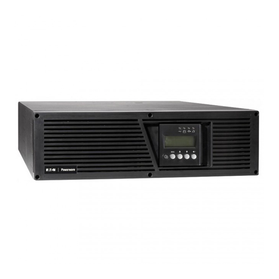
This could cause hours of lost productivity and expensive repairs. With the Eaton 9135 UPS, you can safely eliminate the effects of power disturbances and guard the integrity of your equipment. Figure 1 shows the Eaton 9135 UPS.
-
Page 8: Safety Warnings
Denne manual indeholder vigtige instruktioner, som skal følges under installation og vedligeholdelse af UPS’en og batterierne. Læs venligst alle instruktioner inden betjening af udstyret og gem denne manual mhp. fremtidige opslag. Eaton 9135 5000/6000 VA UPS User’s Guide 164201726—Rev 4 www.eaton.com/powerquality…
-
Page 9
Deze UPS bevat LEVENSGEVAARLIJKE ELEKTRISCHE SPANNING. Alle reparaties en onderhoud dienen UITSLUITEND DOOR ERKEND SERVICEPERSONEEL te worden uitgevoerd. Er bevinden zich GEEN ONDERDELEN in de UPS die DOOR DE GEBRUIKER kunnen worden GEREPAREERD. Eaton 9135 5000/6000 VA UPS User’s Guide 164201726—Rev 4 www.eaton.com/powerquality… -
Page 10
Lue kaikki ohjeet ennen laitteiston käyttöä ja säilytä ohje myöhempää tarvetta varten. VAARA Tämä UPS sisältää HENGENVAARALLISIA JÄNNITTEITÄ. Kaikki korjaukset ja huollot on jätettävä VAIN VALTUUTETUN HUOLTOHENKILÖN TOIMEKSI. UPS ei sisällä MITÄÄN KÄYTTÄJÄN HUOLLETTAVIA OSIA. Eaton 9135 5000/6000 VA UPS User’s Guide 164201726—Rev 4 www.eaton.com/powerquality… -
Page 11
Cet onduleur contient des TENSIONS MORTELLES. Toute opération d’entretien et de réparation doit être EXCLUSIVEMENT CONFIÉE A UN PERSONNEL QUALIFIÉ AGRÉÉ. AUCUNE PIÈCE RÉPARABLE PAR L’UTILISATEUR ne se trouve dans l’onduleur. Eaton 9135 5000/6000 VA UPS User’s Guide 164201726—Rev 4 www.eaton.com/powerquality… -
Page 12
Handbuch zum Nachlesen auf. WARNUNG Die USV führt lebensgefährliche Spannungen. Alle Reparatur- und Wartungsarbeiten sollten nur von Kundendienstfachleuten durchgeführt werden. Die USV enthält keine vom Benutzer zu wartenden Komponenten. Eaton 9135 5000/6000 VA UPS User’s Guide 164201726—Rev 4 www.eaton.com/powerquality… -
Page 13
La TENSIONE contenuta in questo gruppo statico di continuità è LETALE. Tutte le operazioni di riparazione e di manutenzione devono essere effettuate ESCLUSIVAMENTE DA PERSONALE TECNICO AUTORIZZATO. All’interno del gruppo statico di continuità NON vi sono PARTI RIPARABILI DALL’UTENTE. Eaton 9135 5000/6000 VA UPS User’s Guide 164201726—Rev 4 www.eaton.com/powerquality… -
Page 14
FARLIG Denne UPS’en inneholder LIVSFARLIGE SPENNINGER. All reparasjon og service må kun utføres av AUTORISERT SERVICEPERSONALE. BRUKERE KAN IKKE UTFØRE SERVICE PÅ NOEN AV DELENE i UPS’en. Eaton 9135 5000/6000 VA UPS User’s Guide 164201726—Rev 4 www.eaton.com/powerquality… -
Page 15
A UPS contém VOLTAGEM MORTAL. Todos os reparos e assistência técnica devem ser executados SOMENTE POR PESSOAL DA ASSISTÊNCIA TÉCNICA AUTORIZADO. Não há nenhuma PEÇA QUE POSSA SER REPARADA PELO USUÁRIO dentro da UPS. Eaton 9135 5000/6000 VA UPS User’s Guide 164201726—Rev 4 www.eaton.com/powerquality… -
Page 16
прочтите все инструкции. Сохраните данное руководство для дальнейшего использования. ОПАСНО В данном ИБП имеются СМЕРТЕЛЬНО ОПАСНЫЕ НАПРЯЖЕНИЯ. Все работы по ремонту и обслуживанию должны выполняться ТОЛЬКО УПОЛНОМОчЕННЫМ ОБСЛУЖИВАЮЩИМ ПЕРСОНАЛОМ. Внутри ИБП нет узлов, ОБСЛУЖИВАЕМЫХ ПОЛЬЗОВАТЕЛЕМ. Eaton 9135 5000/6000 VA UPS User’s Guide 164201726—Rev 4 www.eaton.com/powerquality… -
Page 17
Este SIE contiene VOLTAJES MORTALES. Todas las reparaciones y el servicio técnico deben ser efectuados SOLAMENTE POR PERSONAL DE SERVICIO TÉCNICO AUTORIZADO. No hay NINGUNA PARTE QUE EL USUARIO PUEDA REPARAR dentro del SIE. Eaton 9135 5000/6000 VA UPS User’s Guide 164201726—Rev 4 www.eaton.com/powerquality… -
Page 18
FARA Denna UPS-enhet innehåller LIVSFARLIG SPÄNNING. ENDAST AUKTORISERAD SERVICEPERSONAL får utföra reparationer eller service. Det finns inga delar som ANVÄNDAREN KAN UTFÖRA SERVICE PÅ inuti UPS-enheten. Eaton 9135 5000/6000 VA UPS User’s Guide 164201726—Rev 4 www.eaton.com/powerquality… -
Page 19
Batterierna måste avyttras enligt anvisningarna i lokal lagstiftning. Använda batterier får aldrig brännas upp. De kan explodera. Byt ut batterierna mot samma antal och typer av batterier som ursprungligen installerats i UPS-enheten. Eaton 9135 5000/6000 VA UPS User’s Guide 164201726—Rev 4 www.eaton.com/powerquality… -
Page 20: Installation
Recycling icons are displayed for easy selection. Verify that the following additional items are included with the UPS: Table 1. UPS Accessory Kit Item Description UPS user’s guide or CD Screwdriver RS-232 serial cable Eaton 9135 5000/6000 VA UPS User’s Guide 164201726—Rev 4 www.eaton.com/powerquality…
-
Page 21
Table 2. EBM Accessory Items Item Description EBM user’s guide EBM cable EBM communication cable Rackmounting kit for 19-inch (48 cm) bays Pedestal extenders for tower position Joining bracket and screws for tower position Eaton 9135 5000/6000 VA UPS User’s Guide 164201726—Rev 4 www.eaton.com/powerquality… -
Page 22: Connecting The Ups Internal Battery
Slide the battery connector so that you can read Connected (see Figure 3). Reinstall the two screws removed in Step 2. Continue to the following section, ”UPS Setup. ” Screws Battery Switch Figure 3. Connecting the Internal Battery Connector Eaton 9135 5000/6000 VA UPS User’s Guide 164201726—Rev 4 www.eaton.com/powerquality…
-
Page 23: Ups Setup
Installation UPS Setup The Eaton 9135 UPS is designed for flexible configurations and can be installed in a rack or as a standalone cabinet. If you are installing the UPS in a rack, continue to the following section, “Rackmount Setup;” otherwise, continue to “Tower Setup”…
-
Page 24
— Place the front panel above the UPS. — Remove the two battery retaining brackets (four screws). — Slightly pull the battery tray, then lift it to extract it. Eaton 9135 5000/6000 VA UPS User’s Guide 164201726—Rev 4 www.eaton.com/powerquality… -
Page 25
Align the mounting brackets with the screw holes on the side of the cabinet and secure with the supplied M4x6 mm flat-head screws. If installing additional cabinets, repeat Steps 3 and 4 for each cabinet. Figure 6. Installing the Mounting Brackets Eaton 9135 5000/6000 VA UPS User’s Guide 164201726—Rev 4 www.eaton.com/powerquality… -
Page 26
11. Optional. Install the rear hold-down brackets (included with the rail kit) if you need to move the rack enclosure with the UPS already rack-mounted inside (see Figure 8). Figure 8. Installing the Rear Hold-Down Brackets Eaton 9135 5000/6000 VA UPS User’s Guide 164201726—Rev 4 www.eaton.com/powerquality… -
Page 27: Tower Setup
DO NOT install the UPS or EBM in a hermetically-closed environment without any exchange of air. The UPS and EBM are heavy (see Table 13 on page 44). A minimum of two people are required to lift the cabinets into the pedestals. Eaton 9135 5000/6000 VA UPS User’s Guide 164201726—Rev 4 www.eaton.com/powerquality…
-
Page 28
UPS Indicators 150 mm (6”) 450 mm (17.7”) Figure 12. Tower Position with One Cabinet Continue to the following section, “Installing the UPS. ” Install pedestal extenders for each additional cabinet: Eaton 9135 5000/6000 VA UPS User’s Guide 164201726—Rev 4 www.eaton.com/powerquality… -
Page 29
Carefully position the cabinet upright with the UPS indicators at the top and place in the pedestals (see Figure 15). Adjust the pedestals to the size of the UPS and secure the pedestals with the captive screws. Figure 15. Tower Position with Two Cabinets Eaton 9135 5000/6000 VA UPS User’s Guide 164201726—Rev 4 www.eaton.com/powerquality… -
Page 30: Installing The Ups
Plug the EBM cable into the battery connector. Plug the EBM communication cable into the RJ-11 port. See Figure 17. Up to four EBMs may be connected to the UPS. Eaton 9135 5000/6000 VA UPS User’s Guide 164201726—Rev 4 www.eaton.com/powerquality…
-
Page 31
If you are installing a remote power-off (RPO) switch, see the following section, “RPO Installation, ” to install the switch before powering on the UPS. Continue to “UPS Electrical Connections” on page 26. Eaton 9135 5000/6000 VA UPS User’s Guide 164201726—Rev 4 www.eaton.com/powerquality… -
Page 32: Rpo Installation
Installation of the RPO function must be carried out in compliance with applicable regulations. The cable is not included. In order to fully de-energize devices and the Eaton 9135 UPS with the RPO port, it is necessary to: Use a two-position switch (normally-open or normally-closed contact and held more than one second). See Figure 18.
-
Page 33: Recommended Upstream Protection
Risk of electrical shock. Before carrying out any connection, check that the battery circuit breaker and UPStream protection device (utility input) are OFF (O). Use included insulated ferrules with stranded wires. Eaton 9135 5000/6000 VA UPS User’s Guide 164201726—Rev 4 www.eaton.com/powerquality…
-
Page 34
Plug the equipment to be protected into the appropriate UPS output receptacles (see Figure 23). IMPORTANT If more than one load is connected to the UPS, the total capacity of the loads should not exceed 30A. Eaton 9135 5000/6000 VA UPS User’s Guide 164201726—Rev 4 www.eaton.com/powerquality… -
Page 35: Ups Rear Panels
2 0 0 − − 2 5 0 V ~ , 2 Figure 23. Connecting the Power Cords UPS Rear Panels This section shows the rear panels of the Eaton 9135 UPS models. (4) L6-30 Receptacles Output Terminal Block Input Cord with L6-30P…
-
Page 36: Operation
The equipment is powered by utility power, but not protected by the UPS. Batteries are recharging. An eight-hour recharge period is necessary to get full backup time. indicators illuminate. To change the factory-set defaults, see “Access to UPS Setup” on page 33. Eaton 9135 5000/6000 VA UPS User’s Guide 164201726—Rev 4 www.eaton.com/powerquality…
-
Page 37: Starting The Ups On Battery
The front panel indicates the UPS status through the UPS indicators. Figure 26 shows the UPS front panel indicators and controls. On Battery Indicator Bypass Indicator Indicator Legend Power On Indicator Alarm Indicator Unlit Flashing On/off Button Figure 26. UPS Front Panel Eaton 9135 5000/6000 VA UPS User’s Guide 164201726—Rev 4 www.eaton.com/powerquality…
-
Page 38: Normal Mode
The UPS transfers to Bypass mode when: The utility power is out of tolerence. There is an overload condition. button is pressed. There is a malfunction. indicators illuminate and the equipment is powered by utility power. Eaton 9135 5000/6000 VA UPS User’s Guide 164201726—Rev 4 www.eaton.com/powerquality…
-
Page 39: Display Functions
Access to UPS Setup To access the UPS Setup menu: Scroll to the UPS Setup menu by pressing the button. Press the button to access the menu. Eaton 9135 5000/6000 VA UPS User’s Guide 164201726—Rev 4 www.eaton.com/powerquality…
-
Page 40
Select I/T network for computer loads. The UPS will stay ONLINE during current limitation, such as when taking on a load. Select Industrial for service continuity. The UPS will transfer to BYPASS during current limitation. Eaton 9135 5000/6000 VA UPS User’s Guide 164201726—Rev 4 www.eaton.com/powerquality… -
Page 41: Access To Maintenance
If disabled, the Eaton warranty will be void. Access to Maintenance To access the Maintenance menu: Scroll to the Maintenance menu by pressing the button. Press the button to access the menu. Figure 29. Access to Maintenance Eaton 9135 5000/6000 VA UPS User’s Guide 164201726—Rev 4 www.eaton.com/powerquality…
-
Page 42: Life Cycle Monitoring
Automatic warnings appear when maintenance actions need to be planned (see Table 10). Table 10. LCM Warning Details LCM Warning Details Signification BATTERY CHECK RECOMMENDED Battery is approaching its reliability end of life. Risk to reduce dramatically backup time. Eaton 9135 5000/6000 VA UPS User’s Guide 164201726—Rev 4 www.eaton.com/powerquality…
-
Page 43: Reset Or Disable Lcm
To disable all LCM messages, select disable all while in the LCM menu. Be careful: if you disable all LCM messages, you will not be aware of any LCM events that can happen on the UPS. Eaton 9135 5000/6000 VA UPS User’s Guide 164201726—Rev 4 www.eaton.com/powerquality…
-
Page 44: Additional Features
Load segments (PowerShare) Communication Ports The Eaton 9135 UPS provides three communication methods that can be used simultaneously: RS-232 or USB communication. Compatible with most power management software applications. Note that both ports cannot be used at the same time.
-
Page 45: Relay Port
1, 2 Not used Remote Power-off signal (527 Vdc, 10 mA max) Operation on mains (not on battery) User common Operation on automatic bypass Low Battery Load protected Operation on battery Eaton 9135 5000/6000 VA UPS User’s Guide 164201726—Rev 4 www.eaton.com/powerquality…
-
Page 46: Network Management Card (Optional)
Remove the slot cover secured by two screws. Insert the communication card into the slot. Secure the card with both screws. Communication Card (restricted access) Figure 33. Network Management Card Eaton 9135 5000/6000 VA UPS User’s Guide 164201726—Rev 4 www.eaton.com/powerquality…
-
Page 47: Maintenance
Remove watches, rings, bracelets and all other metal objects from the hands and arms. Use tools with an insulated handle. When replacing batteries, replace with the same number of the BB/HR5.5-12 batteries. Eaton 9135 5000/6000 VA UPS User’s Guide 164201726—Rev 4 www.eaton.com/powerquality…
-
Page 48: Recycling The Used Battery Or Ups
Slightly pull the battery tray, then lift it to extract it. Replace the battery tray and secure with the battery retaining brackets. NOTE To ensure safety and high performance, use only batteries supplied by Eaton. Replace the UPS front cover. Recycling the Used Battery or UPS Contact your local recycling or hazardous waste center for information on proper disposal of the used battery or UPS.
-
Page 49
Maintenance CAUTION Do not discard waste electrical or electronic equipment (WEEE) in the trash. For proper disposal, contact your local recycling/reuse or hazardous waste center. Eaton 9135 5000/6000 VA UPS User’s Guide 164201726—Rev 4 www.eaton.com/powerquality… -
Page 50: Specifications
Chapter 7 Specifications This chapter provides specifications for the Eaton 9135 5000/6000 VA UPS models. Table 12. Input and Output Specifications AC Input Power Levels (Rated at Nominal Voltage Frequency Model Number Nominal Inputs) Voltage Range Range Voltage Frequency PW9135G5000-XL3UHW…
-
Page 51
1 hr 23 min 6000 VA 4 min 17 min 33 min 50 min 1 hr 7 min NOTE Battery times are approximate and vary depending on the load configuration and battery charge. Eaton 9135 5000/6000 VA UPS User’s Guide 164201726—Rev 4 www.eaton.com/powerquality… -
Page 52: Troubleshooting
In case of “LCM WARNING” , see “Life Cycle Monitoring” on page 36. Escape Down Enter Figure 36. Troubleshooting LED Troubleshooting Not Requiring Eaton Service Figure 37. Environment Fault Eaton 9135 5000/6000 VA UPS User’s Guide 164201726—Rev 4 www.eaton.com/powerquality…
-
Page 53: Troubleshooting Requiring Eaton Service
Troubleshooting Requiring Eaton Service NOTE In case of multiple fault, press the button and the button to get access to further details (see Table 19). Escape Down Enter Figure 38. Troubleshooting LED Eaton 9135 5000/6000 VA UPS User’s Guide 164201726—Rev 4 www.eaton.com/powerquality…
-
Page 54: Service And Support
A replacement or repair unit will be shipped, freight prepaid for all warrantied units. NOTE For critical applications, immediate replacement may be available. Call the Help Desk for the dealer or distributor nearest you. Eaton 9135 5000/6000 VA UPS User’s Guide 164201726—Rev 4 www.eaton.com/powerquality…
-
Page 55: Warranty
LIMITED WARRANTY: This limited warranty (this “Warranty”) applies only to the original End-User (the “End-User”) of any Eaton 3105, 9120, 9125, 9135, 9140, and FERRUPS up to 3.1 kVA Products (individually and collectively, the “Product”) purchased on or after June 1, 2004 and cannot be transferred. This Warranty applies even in the event that the Product is initially sold by Company for resale to an End-User.
-
Page 56
Any costs for replacement equipment, installation, materials, freight charges, travel expenses or labor of Company representatives outside the terms of this Warranty will be borne by the End-User. Eaton 9135 5000/6000 VA UPS User’s Guide 164201726—Rev 4 www.eaton.com/powerquality… -
Page 57
OBTAINING WARRANTY SERVICE: In the USA, call the Customer Reliability Center 7×24 at 800-356-5737 . Outside of the USA, call your local Eaton product sales or service representative, or call the Customer Reliability Center in the USA at 919-870-3149. For comments or questions about this Warranty, write to the Customer Quality Representative, 3301 Spring Forest Road, Raleigh, North Carolina 27616 USA. -
Page 58
TO MAKE A CLAIM: In the USA, call the Customer Reliability Center 7×24 at 800-356-5737 . Outside of the USA, contact your local Eaton product sales or service representative, or call the Customer Reliability Center in the USA at 919-870-3149. For comments or questions about this Load Protection Guaranty, write to the Customer Quality Representative, 3301 Spring Forest Road, Raleigh, North Carolina 27616 USA.
Наш адрес: г. Москва, ул. Полярная, д. 31, стр. 1. Телефон: +7 495 649 16 77 (Skype, ICQ). Режим работы: понедельник — пятница с 9:00 до 18:00; суббота и воскресенье — выходной. Доставка по России, Белоруссии, Украине, Казахстану: Москва, Подольск, Сергиев Посад, Истра, Рязань, Курск, Липецк, Тула, Иваново, Воронеж, Ярославль, Тверь, Смоленск, Калуга, Белгород, Орел,
Тамбов, Кострома, Брянск, Красноярск, Норильск, Кемерово, Новокузнецк, Новосибирск, Омск, Барнаул, Иркутск, Братск, Бийск, Улан-Удэ, Томск, Абакан, Чита, Горно-Алтайск, Кызыл, Санкт-Петербург,
СПб, Выборг, Вологда, Череповец, Мурманск, Сыктывкар, Ухта, Архангельск, Северодвинск, Великий Новгород, Петрозаводск, Гомель, Гродно, Витебск, Могилев, Брест, Минск, Алма-Ата, Астана,
Ереван, Киев, Днепропетровск, Львов, Ташкент, Могилев, Псков, Калининград, Нарьян-Мар, Уфа, Стерлитамак, Самара, Тольятти, Сызрань, Нижний Новгород, Арзамас, Саратов, Энгельс, Пермь,
Ижевск, Казань, Набережные Челны, Бугульма, Пенза, Оренбург, Орск, Чебоксары, Новочебоксарск, Ульяновск, Киров, Йошкар-Ола, Саранск, Екатеринбург, Верхняя Пышма, Серов, Челябинск,
Магнитогорск, Снежинск, Тюмень, Курган, Нижневартовск, Сургут, Надым, Ростов-на-Дону, Волгодонск, Таганрог, Волгоград, Волжский, Краснодар, Армавир, Астрахань, Майкоп, Владивосток,
Уссурийск, Хабаровск, Комсомольск-на-Амуре, Советская Гавань, Южно-Сахалинск, Благовещенск, Петропавловск-Камчатский, Мирный, Ставрополь, Минеральные Воды, Махачкала, Нальчик, Алушта, Армянск, Джанкой, Евпатория, Керчь, Севастополь, Симферополь, Судак, Крым, Феодосия, Ялта. Сайт отвечает на вопросы: Как отремонтировать, настроить, установить оборудование? Где скачать документацию (инструкцию, мануал)? Где посмотреть партномер? Где купить запчасти (запасные
части, зип), комплектующие, аксессуары и термоэтикетка, чековая лента для весов, термопринтеров штрих-кода, чековых принтеров? Обслуживание весов, кассовых аппаратов, термопринтеров,
терминалов сбора данных, сканеров штрих-кода: каким образом возможно своими силами? Вас интересует наличие, цена, купить запчасти за наличный и безналичный расчет? — сделайте запрос
нашим менеджерам. Официальный сайт компании Zipstore.ru.
Диагностика и устранение неисправностей
Руководство пользователя ИБП Eaton
®
9135 «два в одном» (5000/6000 BA)
S
164201894 Rev 1 www.eaton.com/powerquality
49
Диагностика и устранение неисправностей, не требующие технического
обслуживания Eaton
Выход
Ðèñóíîê 42. Ошибка окружающей среды
Нажмите кнопку
для просмотра следующих данных:
Отображаемые данные
Значение
Исправление
NO BATTERY
Неправильно подключена батарея.
Проверьте подключение батареи.
I/O BAD CONNECTION
Неправильное подключение входной электросети.
Проверьте проводку.
НЕТ СИЛОВОГО МОДУЛЯ
Модуль питания не установлен.
Проверьте подключение силового модуля
(см. страницу 43).
НЕТ БАТАРЕЙ
Неправильно подключен блок батареи.
Проверьте подключения батареи (см.
страницу 44).
ПЕРЕГРЕВ ИНВЕРТОРА
ИБП выключается автоматически в результате
серьезной перегрузки.
Проверьте мощность, потребляемую
подключенными устройствами, и отключите менее
важные устройства.
ИНВЕРТЕР В РЕЖИМЕ
ОГРАНИЧЕНИЯ
Состояние короткого замыкания на выходных
устройствах.
Проверьте установку на выходе ИБП (проводка,
неисправное оборудование).
| Найти файл |  |
|
|
|
 |
| Найти DataSheet | |
|
| Сейчас на сайте | |
|
Онлайн всего: 109 Гостей: 97 Пользователей: 12 it-service-42, Gany, loop, Chasthelin, pol924780, Shamsher98, machenist, saxno29, ZimA, OCC, svtv, Jyk |
|
|
| Приветствую Вас, Гость • RSS | 04.06.2023, 03:49:20 |
|
Схемы, блок-диаграммы, коды ошибок для ИБП Eaton серии Powerware |
||||||||||||||
|
В архиве схемы, блок-диаграммы, коды ошибок для ИБП Eaton Powerware следующих моделей: PW3105, PW3110, PW3115, PW5110, PW5115, PW5115RM, PW5119, PW5125, PW5125RM, PW9110, PW9120, PW9125, PW9130, PW9135, PW9140 |
||||||||||||||
|
Чтобы скачать данный файл, нужно Зарегистрироваться, а после пройти Тест на начальные знания радиоэлектронники |
||||||||||||||
|
||||||||||||||
| Всего комментариев: 5 | |
|
Порядок вывода комментариев: День добрый, не знаете ли вы пароль от входа в Service Settings на 9130 еатоне?
Привет! Мне нужен пароль от входа в Service Settings на 9130 еатоне. у тебя нет его? Какой именно файл запоролен? в папке 9130 есть файл pw9130 service manual,открывается без пароля |
|

Добавлять комментарии можно только после регистрации и прохождения Теста.
[ Регистрация | Вход ]
| Информация Файлообменника |
|
Если Вы нашли совпадающие файлы, качество файла плохое и Вы можете поделится лучшим, есть какое-либо несоответствие, схема подходит к другой модели, марки аппарата и т.д … обо всем , что касается Файлообменника, пишите в этой теме |