
Москва
7-23
8 (495) 221-33-33
FAQ
Курсы
Мастер по ремонту холодильников
Мастер по ремонту стиральных машин
Мастер по ремонту телевизоров
Мастер по ремонту кофемашин
Мастер по ремонту швейных машин
Мастер по ремонту кухонных плит
Мастер по ремонту СВЧ-печей
О компании
Новости
СМИ о нас
Отзывы
Сертификаты и награды
Компания
Награды и достижения
Отдел технического контроля
Мастера
Вакансии
Партнеры
Портфолио
Клиентам
Сервисное обслуживание организаций
Транспортировка и установка техники
Гарантия
Программа лояльности
Covid
Сервисный центр Алтуфьево
Неисправности
Контакты
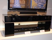
AN-PR1000H
— AN-PR1000HR — Sharp Home Cinema System — Error codes — test mode — SMPS schematic — Disassemble procedure — LED blinkig codes — Failure detection — Test mode — ASPM test mode
SYMPTOM — No Function and error code “ERR80”.
CAUSE — EEPROM errors.
ACTION — When replaced please follow the instructions below.
EEPROM Test — IXA116AW RH-IXA116AW00
• Holding down both the Power and Function Buttons, plug in or turn on the mains supply.
• Unit will enter the Test mode and display the Microprocessor Version number.
• Using the remote press the Sound button.
• The display will show “EEP.Test”.
• Press and hold the Volume down button for longer than 2 Seconds.
• Display will show “EEP.lL”
• Press the Power button twice.
• The display will show “Goodbye”
• The process is now completed.
Entering the test mode
In the AC OFF state, hold down the “FUNCTION” key and press the POWER key. Then switch on AC to enter the test mode route state.
* Be sure to follow the above procedure to enter the test mode.
Exiting the test mode
In the test mode route state, press the POWER key to turn off the system and exit the test mode.
When replacing EEPROM IC, necessary data are not recorded inside; “Protect area
read error” (“ERR 80”) occurs.
To avoid this state, write the data into the corresponding device.
1. Enter the test mode and check set data values of each address according to
the EEPROM set data table on the right. If necessary, change the set data values.
NOTE: (Data are written into EEPROM in the procedure 4 below.)
(Do not disconnect power supply to the product)

Exiting the EEPROM mode from the address value display state. (Press the POWER key once in the address value display state.) (The product enters the test mode route state.)
Exiting
the test mode
(Press the POWER key once in the test mode route state.)
(Then the data are written into EEPROM. After the write operation, the product
enters the standby state.)
After
checking that the product enters the standby state, stop power supply to the
product.
(This operation initializes the error state.)
* Operation ends.
To
Check And Cancel Protect Circuit Detection
1. After the power is turned on, the microprocessor (ICM7) built in this model
continuously monitors the following defective operation. If any abnormality
occurs, all power is shut down except in the microprocessor drive circuit.
1) An abnormal drop of each regulator output voltage. (The protection circuit
operates when the regulator output voltage is below 1.5 V.) The power is shut
down immediately with no display.
2) Defect of the cooling fan motor and the cooling fan drive circuit. (Stoppage,
etc.) The power is turned off after “FAN LOCK” is displayed.
3)
Over voltage or reduced voltage of power supply. The power is shut down immediately with no
display when voltage is abnormal.
2. Failure detection conditions of the built-in microprocessor, check of the
detection line and solution.
Conditions
1) To detect failure according to voltage of the microprocessor ICM7 pin 91.
2) Abnormal if pulse signals are not input into the pin 5 (FAN LOCK) for more
than 5 seconds.
3) Abnormal if the voltage of the pin 97 (+B CHECK) is lower than 1.2 V or
higher than 3.0 V.
Check
of the detection line and solution
NOTE: If the microprocessor detects failures of 1), 2) and 3) above, it does
not operate protectively when its PROTECT, and +B CHECK detection lines are
disconnected. When these failures are
caused by output short-circuit of each regulator, components and PWB of the
regulator may burn
out. If the cause is not clear, do not disconnect the detection line.
(Even if any failure is detected, conduction is available for 0.5 second. You
can check conduction by an oscilloscope, etc.
However, a tester is not available due to rapid rise and decay of
voltage.)
When
output voltage of each regulator drops abnormally.
Connect the oscilloscope to the regulated output of the regulator and power on
the system. If the voltage is significantly lower than that shown in the
circuit diagram (approx. 1.5 V or less), the regulator itself and the
destination circuit are suspected.
Failure
Detection Identification Using STANDBY LED
Identification
format using STANDBY LED
If any failure is detected, STANDBY LED blinks red after power off. You can
identify the failure state by checking which LED output number from the frame
head is blinking 4 times each for 2 seconds.
Normally,
LED light up for 2 seconds and light off for 1 second on a 3-second cycle (6
times from No. 1 to No. 6). For No.7, LED light off for 3 seconds, showing the
frame end (for recognition of the frame head).
In No. 2, LED blinks alternately at shorter intervals than usual for failure
identification. For failure status, refer to the appendix, “STAND-BY LED Error
Message”
Failure detection
1. SYS-PROTECT detection: To detect failure of the power supply circuit (except the 1.8 V power supply circuit).
2. B_CHECK detection: To check timing at power ON/OFF and detect over voltage and reduced voltage of the primary AC power after the power is turned on.
SYS-PROTECT detection => immediate power shut-down; Identification No.1 blinking
B_CHECK detection => immediate power shut-down; Identification No.2 blinking in case of over voltage No blinking in case of reduced voltage.
AVCK detection => immediate power shut-down; Identification No.3 blinking
AMP_SW_PROT detection => immediate power shut-down; Identification No.6 blinking.
Error messages

Disassemble procedure

SMPS circuit diagram


ASPM Test Mode (For EU Destination)
At Tuner RDS ASPM operation need to be confirm for EU(H) model only.
Power-ON in TUNER function, and scanning frequency from 105.00MHz — 108.00MHz.
And RDS station Preset Memory maximum 3 stations.
TEST
Mode Operation
Power ON in TUNER Function 106.50MHz FM Stereo Band. At same time Only Preset
No. ch1 — ch3 leave blank and all ch4 — ch40 memory at 87.50MHz FM Stereo Band.
With the press of ASPM key, ASPM operation will start at 105.00MHz
frequency. If RDS station received
Preset will memory from ch1. (There is no need to memory PS name in ASPM Test
Mode. If preset change during Test Mode Frequency will be display first)
Scan will stop after reach frequency 108.00MHz, and return to frequency
106.50MHz FM Stereo.
To confirm Memory content display will show Preset Number and frequency for
ch1until ch3. After display is confirmed frequency will return to 106.50MHz FM
STEREO. (Display method same with Tuner display during Normal POWER ON.)
If
ASPM key is press again, ASPM operation will start from 2 until 5.
While scanning if 3 station memorized, Scanning will stop and operation 4 and 5
will take place.
Afterward, even if ASPM key input detects ASPM operation will not be execute.
«__END__» displayed and operation canceled.
Other
then above, operations for ASPM are same with User operation. So, when 1st time
scan with same PI code Station with most strong signal will be memory and will
not be memory many time. For 2nd and more station with same frequency will not
be memory.
But, if different station with same PI code (same PI with different frequency
station), station one with most strong signal will be memory.
So, station that already memorized before scan will be ignore. Therefore, even station with same same PI
code after 3 times ASPM scan; it is possible that, 3 station will be memorized
in Signal Strong order.
After Test Mode end only Tuner preset memory will be reset and set to default.
Others Memory, no need to be initializing.
При использовании любой техники время от времени могут возникать неполадки. Так, например, при использовании копиров, принтеров и МФУ Sharpмогут появляться различные ошибки, вызванные различными причинами. Об их возникновении пользователь информируется с помощью кода, которые выводится на дисплее принтера или другого используемого устройства. Коды ошибок Sharp вы можете идентифицировать с помощью приведенной ниже таблицы. Выяснив причину сбоя в работе устройства, вы сможете устранить ее самостоятельно (например, если произошло замятие бумаги, отсутствует бумага в лотке) либо обратиться в сервисный центр по обслуживанию и ремонту Sharp, если код ошибки сообщает о серьезной поломке.
Sharp AL-840
| Код ошибки | Подкод | Описание |
|---|---|---|
| L1 | 00 | Неисправность при движении сканирующего устройства |
| L3 | 00 | Неисправность сканирующего устройства при возвращении в начальное положение |
| Е7 | 03 | Неисправность, связанная с яркостью свечения лазера |
| 04 | Ошибка при определении уровня белого при выполнении штриховки | |
| 05 | Ошибка при определении уровня черного при выполнении штриховки | |
| 12 | Ошибка уровня выходного сигнала при выполнении штриховки | |
| 14 | Сбой ASIC (MCU PWB) | |
| 15 | Неисправность копировальной лампы | |
| H2 | 00 | Неисправность термодатчика |
| H3 | 00 | Температура вала узла закрепления превысила норму |
| H4 | 00 | Температура вала узла закрепления опустилась ниже положенного уровня |
| U2 | 01 | Неисправность EEPROM (MCU PWB) (ошибка данных счетчика) |
| 04 | Неисправность EEPROM (MCU PWB) (ошибка записи/чтения) | |
| 05 | Неисправность EEPROM (MCU PWB) | |
| 06 | Неисправность ROM (MCU PWB) | |
| C1 | Неисправность, обнаруженная выключателем передней панели (блока питания) | |
| CH | Отсутствует тонер-картридж | |
| E1 | Замятие бумаги при подаче из лотка | |
| E2 | Замятие бумаги | |
| E3 | Замятие бумаги на выходе узла закрепления | |
| P | Отсутствие бумаги в лотке |
Sharp AL-1000
| Код ошибки | Подкод | Описание |
|---|---|---|
| E7 | 03 | Неисправность блока лазера, связанная с излучающим диодом и его цепями |
| 04 | Ошибка при определении уровня белого при выполнении штриховки | |
| 05 | Ошибка при определении уровня черного при выполнении штриховки | |
| 12 | Ошибка уровня выходного сигнала при выполнении штриховки | |
| 14 | Сбой ASIC (MCU PWB) | |
| 15 | Неисправность копировальной лампы | |
| L1 | 00 | Неисправность при движении сканирующего устройства (датчик начального положения сканирующего устройства не видит движения зеркал) |
| L3 | 00 | Неисправность сканирующего устройства при возвращении в начальное положение (сканер не успел вернутся в начальное положение за определенное время) |
| L4 | 01 | Main motor drive overloaded |
| L6 | 10 | Неисправность двигателя многогранника блока лазера (полигон-мотор) |
| H2 | 00 | Неисправность термодатчика |
| H3 | 00 | Температура вала узла закрепления превысила норму |
| H4 | 00 | Температура вала узла закрепления опустилась ниже положенного уровня |
| U2 | 01 | Неисправность EEPROM (MCU PWB) (ошибка данных счетчика) |
| 04 | Неисправность EEPROM (MCU PWB) (ошибка записи/чтения) | |
| CH | Отсутствует тонер-картридж |
Sharp AL-1010
| Код ошибки | Подкод | Описание |
|---|---|---|
| E7 | 03 | Scanner position error |
| 04 | Exposure lamp blown | |
| 05 | CCD calibration error | |
| 12 | White level calibration error | |
| 14 | Main board malfunction | |
| 15 | Exposure lamp blown | |
| L1 | 00 | Scanner position error |
| L3 | 00 | Scanner position error |
| L4 | 01 | Main motor drive overloaded |
| L6 | 10 | Polygon mirror motor not up to speed |
| H2 | 00 | Fusing unit temperature error |
| H3 | 00 | Overheated fusing unit |
| H4 | 00 | The fusing unit doesn’t heat up |
| U2 | 01 | Counter error |
| 04 | EPROM error | |
| CH blinking | Dev unit is not properly installed |
Sharp AR-160 / 161
| Код ошибки | Подкод | Описание |
|---|---|---|
| CC | Original not detected | |
| E1 | 00 | Lost communication with the Sorter |
| 10 | Lost communication with the Sorter | |
| 11 | ASIC error | |
| 12 | Image Processing Unit error | |
| 13 | ROM error | |
| 14 | NVRAM error | |
| 15 | Page memory fault | |
| 16 | SIMM not present or installed incorectly | |
| 17 | Page rotation error in RAM | |
| 80 | Electronic sort board error | |
| 81 | ||
| 82 | ||
| 84 | ||
| 88 | ||
| E7 | 03 | Lens position error |
| 04 | White level calibration error | |
| 05 | Black level calibration error | |
| 12 | CCD calibration error | |
| F1 | 06 | Shift sort motor overloaded |
| F5 | 02 | Exposure lamp blown |
| F6 | 00 | Fax board problems |
| 10 | ||
| 80 | ||
| 81 | ||
| 82 | ||
| 84 | ||
| 88 | ||
| F9 | 00 | Printer board problems |
| 10 | ||
| 80 | ||
| 81 | ||
| 82 | ||
| 84 | ||
| 88 | ||
| H2 | 00 | Fusing unit temperature error |
| H3 | 00 | Overheated fusing unit |
| H4 | 00 | The fusing unit doesn’t heat up |
| L1 | 00 | Scanner position error |
| L3 | 00 | Scanner position error |
| L4 | 01 | Main motor drive overloaded |
| 10 | Separation motor overloaded | |
| L6 | 10 | Polygon mirror motor not up to speed |
| L8 | 01 | Zero cross signal error |
| U2 | 04 | EPROM error |
| 11 | Main counter error | |
| 12 | EPROM error | |
| U3 | 29 | Mirror position error |
| U9 | 00 | Op panel problem |
| 81 | ||
| 82 | ||
| 84 | ||
| 88 | ||
| U95 | Firmware error |
Sharp AR-163 / 201 / 206 / 5015 / 5020
| Код ошибки | Подкод | Описание |
|---|---|---|
| E1 | 00 | Неисправность связи с платой электронного сортировщика |
| 10 | Неисправность платы электронного сортировщика | |
| 11 | Ошибка ASIC электронного сортировщика | |
| 12 | Ошибка CODEC электронного сортировщика | |
| 13 | Ошибка очистки (сброса) ROM электронного сортировщика | |
| 14 | Ошибка RAM электронного сортировщика | |
| 15 | Ошибка сохранения страницы в памяти электронного сортировщика | |
| 16 | Ошибка SIMM электронного сортировщика | |
| 17 | Ошибка RAM | |
| 80 | Неисправность связи с платой электронного сортировщика (PROTOCOL) | |
| 81 | Неисправность связи с платой электронного сортировщика (PARITY) | |
| 82 | Неисправность связи с платой электронного сортировщика (OVERRUN) | |
| 84 | Неисправность связи с платой электронного сортировщика (FRAMING) | |
| 88 | Неисправность связи с платой электронного сортировщика (TIME-OUT) | |
| E7 | 03 | Неисправность блока лазера |
| 04 | Ошибка определения уровня белого CCD | |
| 05 | Ошибка при определении уровня черного CCD | |
| F1 | 06 | Неисправность Shifter (двигателя сдвига копии) |
| F2 | 04 | Ошибка чтения данных CRUM (чипа тонер-картриджа) |
| F5 | 02 | Неисправность копировальной лампы |
| F6 | 00 | Ошибка связи с платой факса |
| 10 | Неисправность платы факса | |
| 80 | Ошибка связи с платой факса (PROTOCOL) | |
| 81 | Ошибка связи с платой факса (PARITY) | |
| 82 | Ошибка связи с платой факса (OVERRUN) | |
| 84 | Ошибка связи с платой факса (FRAMING) | |
| 88 | Ошибка связи с платой факса (TIME-OUT) | |
| F9 | 00 | Ошибка связи с платой принтера |
| 10 | Неисправность платы принтера | |
| 80 | Ошибка связи с платой принтера (PROTOCOL) | |
| 81 | Ошибка связи с платой принтера (PARITY) | |
| 82 | Ошибка связи с платой принтера (OVERRUN) | |
| 84 | Ошибка связи с платой принтера (FRAMING) | |
| 88 | Ошибка связи с платой принтера (TIME-OUT) | |
| H2 | 00 | Неисправность термодатчика |
| H3 | 00 | Температура вала узла закрепления превысила норму |
| H4 | 00 | Температура вала узла закрепления опустилась ниже положенного уровня |
| L1 | 00 | Обнаружена неисправность при определении начального положения сканирующей каретки |
| L3 | 00 | Обнаружена неисправность при обратном ходе сканирующей каретки |
| L4 | 01 | Неисправность главного двигателя |
| 10 | Неисправность двигателя сепаратора | |
| L6 | 10 | Неисправность двигателя многогранника блока лазера (полигон-мотор) |
| L8 | 01 | Ошибка сигнала пересечения нуля |
| U2 | 04 | EEPROM serial communication error |
| 11 | counter check sum error | |
| 12 | adjustment value check sum error(EEPROM) | |
| 40 | CRUM communication error | |
| U3 | 29 | Ошибка в определении начального положения зеркал |
| U9 | 00 | Ошибка связи с панелью управления (PROTOCOL) |
| 80 | Ошибка связи с панелью управления (PARITY) | |
| 82 | Ошибка связи с панелью управления (OVERRUN) | |
| 84 | Ошибка связи с панелью управления (FRAMING) | |
| 88 | Ошибка связи с панелью управления (TIME-OUT) | |
| U95 | Неисправность соединения платы управления | |
| U99 |
Sharp AR-405
| Код ошибки | Подкод | Описание |
|---|---|---|
| C1 | 00 | MC unit malfunction |
| C2 | 00 | TC unit malfunction |
| E7 | 00 | Image Processing Unit error |
| 01 | Memory back-up battery dead | |
| 02 | Laser unit problem | |
| 03 | HDD defective | |
| 10 | black level calibration error | |
| 11 | white level calibration error | |
| 13 | CCD calibration error | |
| 90 | Image Processing Unit error | |
| F1 | 00 | Lost communication with the Sorter |
| 01 | Sorter registration problem | |
| 02 | Paper transport motor overloaded in sorter | |
| 04 | Bin position error in sorter | |
| 05 | Bin position error in sorter | |
| 06 | Shift sort motor overloaded | |
| 08 | Stapler position error | |
| 08 | Stapler overloaded | |
| 11 | Sorter problems | |
| 14 | Second shift tray jammed | |
| 15 | Sorter drive problems | |
| 50 | Sorter not installed properly | |
| 80 | No powerin sorter | |
| F2 | 00 | ID pattern reading error |
| 02 | Toner add mechanism malfunction | |
| 31 | ID pattern reading error | |
| 32 | ID pattern reading error | |
| 39 | Drum thermistor error | |
| F3 | 12 | Paper does not lift in the tray |
| 22 | Paper does not lift in the tray | |
| F9 | 00 | Printer board problems |
| 01 | Printer board problems | |
| 02 | Printer board problems | |
| 03 | Network card error | |
| 04 | Firmware error | |
| 05 | Not enough memory | |
| 10 | Printer board problems | |
| 90 | Printer board problems | |
| H2 | 00 | Fusing unit temperature error |
| 01 | Fusing unit temperature error | |
| H3 | 00 | Overheated fusing unit |
| 01 | Overheated fusing unit | |
| H4 | 00 | The fusing unit doesn’t heat up |
| 01 | The fusing unit doesn’t heat up | |
| H5 | 01 | Papersensordefective in the fusing unit |
| 02 | Fusing unit temperature error | |
| L1 | 00 | Scanner position error |
| L3 | 00 | Scanner position error |
| L4 | 01 | Main motor drive overloaded |
| L6 | 10 | Polygon mirror motor not up to speed |
| L8 | 01 | Zero cross signal error |
| 02 | Zero cross signal error | |
| U2 | 00 | EPROM error |
| 11 | EPROM error | |
| U4 | 02 | Duplex not working properly |
| 03 | Duplex problems | |
| U5 | 00 | Communication with the ADF is lost |
| 01 | Registration sensor problem in ADF | |
| 02 | Exit sensor error in ADF | |
| 03 | Timing sensor problems in ADF | |
| 11 | Paper feed drive overloaded in ADF | |
| U6 | 01 | Paper lift problem in 1’st optional tray |
| 02 | Paper lift problem in 2’nd optional tray | |
| 08 | Paper feed unit without power | |
| 10 | PFU paper transport motor overloaded | |
| 22 | Paper feed unit without power | |
| 50 | Paper feed unit not installed properly | |
| 51 | LCT not installed properly | |
| U7 | 00 | Main board malfunction |
| U9 | 00 | Op panel problem |
| 90 | Op panel problem | |
| EE | EU | Low toner density in the developer |
| EE | EL | High toner density in the developer |
| FA | 01 | Memory back-up battery dead |
| PC | Key counter not installed |