
|
|
Ремонт частотных преобразователей HYUNDAI
 Ремонт частотного преобразователя HYUNDAI, впрочем, как и ремонт частотников других производителей имеет ряд особенностей в силу своего конструктива. Частотные преобразователи, точнее их начинка делятся на две части:
- Аппаратная часть,
- Программная часть.
Частотники данного производителя не являются исключением из правил, именно поэтому ремонт частотного преобразователя HYUNDAI имеет точно такой же ряд особенностей, как и у других преобразователей.
Диагностировать ту или иную неисправность помогают коды ошибок частотного преобразователя, которые отображаются на небольшом дисплее, расположенном на лицевой панели привода. Коды ошибок частотного преобразователя HYUNDAI в зависимости от серии описаны в инструкции, пользователя которые можно скачать с нашего сайта.
Ремонт частотных преобразователей HYUNDAI в , как и любых других преобразователей, выпущенных под другими брендами, всегда начинается с аппаратной части, и только после успешной реанимации аппаратной части наступает очередь программной.
Настройка частотного преобразователя HYUNDAI также прописана в инструкции завода производителя, для каждой серии частотных преобразователей настройка будет индивидуальной, так как каждая линейка преобразователей решает свои собственные задачи, этим обусловливается широкая номенклатура данного промышленного оборудования.
Ремонт частотных преобразователей HYUNDAI в сервисном центре
 Компания «Кернел» производит ремонт частотных преобразователей HYUNDAI в с 2002 года. За время существования компании наши сотрудники накопили колоссальный опыт в ремонте преобразователей частоты такого известного производителя как HYUNDAI. Ремонт подобного промышленного оборудования ответственное и сложное занятие, требующие максимальной отдачи, профессионализма и максимально полной материальной базе.
Специалисты нашего сервисного центра максимальное внимание уделяют качеству исполнения ремонта, программирования и настройке промышленных преобразователей частоты, не зависимо от производителя данного промышленного оборудования. Именно поэтому мы смело даем гарантию на ремонт частотных преобразователей HYUNDAI а также на запасные части замененные в процессе ремонта шесть месяцев.
Ремонт частотных преобразователей HYUNDAI в производится исключительно с использованием оригинальных запасных частей, на компонентном уровне с применением высокотехнологичного диагностического оборудования, квалифицированным персоналом с инженерным образованием.
В случае выхода из строя преобразователя частоты на вашем производстве либо появились проблемы с приводом, которые вы не можете решить самостоятельно, мы всегда рады вам помочь. Специалисты нашего сервисного центра в минимальные сроки проведут глубокую диагностику неисправного оборудования и последующий ремонт частотного преобразователя HYUNDAI.
Инженеры сервисного центра выполняют качественный ремонт частотных преобразователей HYUNDAI всех серий, когда-либо выпускаемых компанией.
|
HYUNDAI N50 |
N50-007SF, N50 -015SF, N50 -022SF |
|
HYUNDAI N100 |
N100-004SF, N100-007LF, N100-004HF, N100-015SF, N100- 007HF, N100-037LF, N100-037HF, N100-055LF, N100-037HFK1.2, N100- 075HFK1.2 |
|
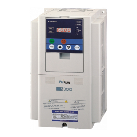
HYUNDAI N300 |
N300-055LF, N300-055HF, N300-075LF, N300-110HF, N300-300LF, N300-300HF, N300-550LF, N300-750, N300-900HF, N300-1100HF |
|
HYUNDAI N300P |
N300-055LFP, N300-110LFP, N300-185LFP, N300-300LFP, N300-110HFP, N300-185HFP, N300-300HFP, N300-450HFP, N300-750HFP |
|
HYUNDAI N500 |
N5000-0155L, N5000-0325L, N5000-1500L, N5000-1310M, N5000-1900M, N5000-2460M, N5000-3450H, N5000-4500H, N5000-5000H, N5000-6400H |
|
HYUNDAI N700V |
N700-055LF/055HF, N700-110LF/110HF, N700-185LF/185HF, N700-300LF/300HF, N700-450LF/450HF, N700-750LF/900HF, N700-1100LF/1320HF |
|
HYUNDAI N700E |
N700E-004SF, N700E-015SF, N700E-004LF, N700E-022LF, N700E-075LF, N700E-185HF, N700E-300HF, N700E-550HF, N700E-1100HF |
В данной таблице присутствуют далеко не все частотные преобразователи и сервопривода HYUNDAI ремонт которых предлагает наш сервисный центр.
Настройка частотного преобразователя HYUNDAI, программирование
 Настройка частотных преобразователей HYUNDAI (программирование) происходит в рамках установленных производителем правил, существует общий алгоритм по программированию (настройке частотных преобразователей), относящийся ко всем производителям данного промышленного оборудования. Ниже представлена пошаговая инструкция по настройке частотных преобразователей HYUNDAI.
- Выбор режима управления приводом HYUNDAI (управление по показанию датчиков, дистанционное управление, дистанционное управление).
- В случае использования отдельного (выносного) монитора, настраивается вывод на него технической информации.
- Далее определяем конфигурацию подключения серводвигателя. На данной стадии задаются такие параметры как- возможность применения обратной связи либо без ее применения, а в память блока заносятся данные по: величине крутящего момента, мощности потребителей, номинальное значения частоты, напряжение, ток и скорости вращения ротора.
- Программируется минимально допустимая величина напряжения и частоты, а также время ускорения ротора от ноля до номинального значения.
- И в завершении, в программу управления частотным преобразователем HYUNDAI вносятся функциональные данные со значениями отдельных клемм и особенностями сигналов. Отмечаются действия оборудования, выполняющиеся автоматически при отсутствии информации поступающей в оперативном режиме с датчика.
В некоторых частотниках существует пункт наличия/отсутствия фильтра в цепи питания двигателя. Этот пункт отвечает за подключение различных видов нагрузок, в том случае, когда возможно выбрать нормальное или инверсное изменение частоты при повышении уровня сигнала обратной связи.
Все настройки частотных преобразователей HYUNDAI приведены в технической документации ниже в удобном формате (PDF) который можно скачать на свой компьютер, распечатать или просто открыть на нашем сайте.
Коды ошибок частотного преобразователя HYUNDAI
 В процессе работы выходит из строя даже самое надежное промышленное оборудование. В данной статье мы приведем ошибки частотного преобразователя HYUNDAI, а точнее HYUNDAI N300. Частотники в наше время нашли широкое применение в абсолютно всех сферах промышленности управляя как мини моторами в оргтехнике, так и гигантскими двигателями в горнодобывающей промышленности.
Для простоты общения со столь сложной электроникой все частотные преобразователи оснащены небольшими дисплеями с помощью которых выводятся информационные сообщения с кодами ошибок, расшифровав которые можно сразу же узнать причину ее возникновения. Если учесть распространенность данной промышленной электроники, то появляется острая нужда в расшифровке кодов ошибок частотных преобразователей. В этой статье мы рассмотрим одного из самых известных производителей промышленной электроники имеющему уважение во всем мире, HYUNDAI.
Существует несколько видов ошибок частотных преобразователей, некоторые из них можно устранить автоматически, а некоторые возможно исправить только, обратившись в специализированный сервисный центр. В таблицах ниже приведены коды ошибок частотного преобразователя HYUNDAI N300 и их расшифровка.
Ошибки частотных преобразователей HYUNDAI N300
|
Код ошибки |
Описание |
Причина |
Дистанционный пульт оператора ERR1*** |
|
|
E01 |
Защита от перегрузки по току. |
При возникновении замыкания на выходе, при блокировке вала двигателя, а также при резком торможении, через инвертор протекает большой ток. Если ток превышает определенное значение, выход отключается. |
При постоянной скорости. |
OC. Drive |
|
E02 |
При торможении. |
OC. Drive |
||
|
E03 |
В других случаях. |
OC. Acce1 |
||
|
E05 |
Защита от перегрузки. |
При определении электронным тепловым реле перегрузки двигателя, выход инвертора отключается. |
Over. L |
|
|
E06 |
Защита от перегрузки тормозного резистора. |
Если время торможения превышает установленный в b090 коэффициент, выход инвертора отключается. |
OL. BRD |
|
|
E07 |
Защита от повышенного напряжения. |
Если из-за регенеративной энергии от двигателя, напряжение инвертора превышает определенный уровень, включается защитная функция и выход инвертора отключается. |
Over. L |
|
|
E08 |
Ошибка EEPROM. |
Если возникают проблемы со встроенной памятью из-за помех или чрезмерного повышения температуры, включается защитная функция и выход инвертора отключается. |
EEPROM |
|
|
E09 |
Защита от недостаточного уровня напряжения. |
Уменьшение входного напряжения инвертора приводит к неправильному функционированию цепи управления. Это также приводит к нагреву двигателя и снижению момента. Выход отключается, если входное напряжение снижается до менее чем 300-320 В. |
Under. V |
|
|
E10 |
Ошибка CT. |
Отклонения от нормы в работе встроенного датчика тока приводят к отключению выхода. |
CT |
|
|
E11 |
Ошибка CPU. |
Нарушения или отклонения в работе встроенного CPU приводят к отключению выхода. |
CPU1 |
|
|
E12 |
Внешний сбой. |
Если происходит сбой в работе внешних устройств, выход отключается (если выбрана функция «Внешний сбой»). |
EXTERNAL |
|
|
E13 |
Ошибка USP. |
Если включить питание инвертора при поданной команде на функционирование, возникает ошибка USP (если установлена функция USP). |
USP |
|
|
E14 |
Защита от замыкания на землю. |
Инвертор определяет короткое замыкание на землю между выходом инвертора и двигателем при включении питания. Существует вероятность повреждения модуля питания. |
GND. F1t |
|
|
E15 |
Защита от перенапряжения на входе. |
Если входное напряжение превышает установленное значение, это определяется через 100 секунд после включения питания, после чего выход отключается. |
OV. SRC |
|
|
E16 |
Внезапный провал напряжения питания. |
Если происходит внезапный провал питания на более чем 15 мс, выход отключается. Если происходит провал питания на длительное время, появляется сигнал о сбое. Обратите внимание, что если установлена функция рестарта, оборудование возобновит работу при восстановлении питания, если не отменена команда на функционирование. |
Inst. P-F |
|
|
E21 |
Перегрев радиатора. |
Если температура радиатора поднимается из –за остановки охлаждающего вентилятора, выход отключается. |
OH. FIN |
|
|
E23 |
Сбой в схеме управления. |
При обнаружении ошибки связи между CPU и схемой управления, инвертор отключается на выходе. |
||
|
E24 |
Защита от неполнофазного режима работы. |
Если на входе инвертора R(L1), S(L2), T(L3) определен провал фазы, выход отключается. |
PH. Fail |
|
|
E30 |
Защита IGBT – модуля. |
При обнаружении перегрузки по току на выходе, инвертор отключится для защиты IGBT-модуля. |
IGBT |
|
|
E35 |
Термозащита с внешнего терморезистора. |
При увеличении сопротивления терморезистора, встроенного в двигатель, инвертор отключается на выходе. |
TH |
|
|
E36 |
Сбои в режиме приостановки разгона / замедления. |
Сбои в режиме приостановки разгона/замедления (Если в функции b120 установлен код 01). |
BRAKE |
|
|
E60 — E69 |
Ошибка опции 1 (0 – 9). |
Если на дисплее высвечивается сообщение о сбое опции 1 (разъем для подключения дополнительных плат), необходимо пользоваться инструкцией по эксплуатации на применяемую дополнительную плату. |
OP1. 0-9 |
|
|
E70 — E79 |
Ошибка опции 2 (0 – 9). |
Если на дисплее высвечивается сообщение о сбое опции 2 (разъем для подключения дополнительных плат), необходимо пользоваться инструкцией по эксплуатации на применяемую дополнительную плату. |
OP2. 0-9 |
|
|
_ _ U |
Ожидание перезапуска во время провалов напряжения питания. |
Во время провалов напряжения питания инвертор отключается на выходе. При активизированной функции автоматического перезапуска на дисплей выводится следующее сообщение. |
UV. WAIT |
 Примечание 1: Через 10 секунд после отключения перезапуск привода производится подачей команды Reset.
Примечание 2: При возникновении ошибки EEPROM [E08] необходимо проверить условия эксплуатации и заново запрограммировать параметры.
Преобразователь частоты разработан таким образом, что он пытается избежать аварийных отключений путем ограничения момента, перенапряжения и т.п.
Появление сбоев при вводе в эксплуатацию или вскоре после него обычно свидетельствует о неверной настройке или неправильном подключении. Возникновение неисправностей или проблем после длительного режима бесперебойной работы обычно происходит по причине изменений в системе или ее окружении (например, в результате износа).
Дополнительную информацию по частотным преобразователям HYUNDAI можно посмотреть и скачать в файлах ниже.
Частотный преобразователь HYUNDAI, скачать инструкции по эксплуатации
Скачать руководства по эксплуатации частотных преобразователей HYUNDAI
|
Частотный преобразователь HYUNDAI N50 инструкция |
 Скачать PDF Скачать PDF |
|
Частотный преобразователь HYUNDAI N100 инструкция |
Скачать PDF |
|
Частотный преобразователь HYUNDAI N300 инструкция |
Скачать PDF |
|
Частотный преобразователь HYUNDAI N300P инструкция |
Скачать PDF |
|
Частотный преобразователь HYUNDAI N700E инструкция |
Скачать PDF |
|
Частотный преобразователь HYUNDAI N700V инструкция |
Скачать PDF |
|
Частотный преобразователь N5000 инструкция |
Скачать PDF |
Схемы подключения частотного преобразователя HYUNDAI
Схемы подключений частотных преобразователей HYUNDAI могут, отличатся друг от друга даже если эти преобразователи относятся ко одной линейке. Схема подключения преобразователя зависит от многих факторов таких как потребляемая частотным преобразователем нагрузка или питающая сеть к которой подключается частотник 200V – 380V и конечно же зависит от CPU в паре, с которым предполагается работа преобразователя.
|
Схема подключения частотного преобразователя HYUNDAI N700E |
Схема подключения частотного преобразователя HYUNDAI N700V |
|
|

|

Схемы подключений частотных преобразователей HYUNDAI других серий вы найдете в руководстве пользователя
Оставьте заявку на ремонт промышленного оборудования, используя форму на сайте, либо свяжетесь с нашими менеджерами, сделать это очень просто.
Оставить заявку на ремонт частотных преобразователей HYUNDAI
У вас вышел из строя частотник? Вам необходим срочный ремонт частотных преобразователей HYUNDAI в ? Оставьте заявку на ремонт нажав на одноименную кнопку в верхней правой части экрана либо свяжитесь с нашими менеджерами. Связаться с ними можно несколькими способами:

- Заказав обратный звонок (кнопка в правом нижнем углу сайта)
- Посредством чата (кнопка расположена с левой стороны сайта)
- Позвонив по номеру телефона:
- +7(8482) 79-78-54;
- +7(8482) 55-96-39;
- +7(917) 121-53-01
- Написав на электронную почту: 89171215301@mail.ru
Далеко не полный список производителей промышленной электроники и оборудования, ремонтируемой в нашей компании.

Рекомендуемые сообщения
-
#1
Всем здравствовать! Прошу помощи и совета у знающих людей. Перестал работать частотник, без дыма и гари, просто выдаёт ошибку Е23 (ошибка связи с процессором). Не долго думая отключаю его и везу в сервис, благо услуга диагностики бесплатная. Мастер озвучил диагноз ; сгорел верхний процессор; Другими словами силовая часть в норме а управления ей нет. На вопрос о замене процессора мастер сказал что если его и заказать в каком китае, то его после перепайки ещё и прошить нужно, а это уже проблема и открестился от моего предложения. Так вот вопрос, что же делать? Выбрасывать или разбирать на з.части жалко, покупать аналогичный с поломкой выходного каскада и из двух собирать один тоже вряд ли, по тому что такого предложения можно долго ждать. Или может собрать управление самостоятельно, пусть не с таким количеством настроек и функционала? Готов на любые эксперименты, если у кого есть идеи по воскрешению преобразователя прошу делиться!!! Р.С. Из функционала нужна только регулировка оборотов двигателя.

Изменено 24.06.2017 19:33 пользователем No smoking
Поделиться сообщением
Ссылка на сообщение
-
#2
Это проще всего. И правильнее. Если есть желание поэкспериментировать — можете на микросхеме типа mp3phac или stm32 с библиотеками для управления асинхронником собрать свой частотник, конечно, только затраты времени на отладку и реализацию функций не окупит стоимость разработки. Готовый частотник стоит сильно дешевле.
Поделиться сообщением
Ссылка на сообщение
-
#3
Неужели всё так безнадёжно и не ремонтируется? Я честно признаться думал что меня мастера в сервисе разводят и подводят к покупке частотника у них.
Поделиться сообщением
Ссылка на сообщение
-
#4
Купить такой же, новый. Если потом в нём сгорит силовуха, то из двух трупиков можно собрать один живенький 
Поделиться сообщением
Ссылка на сообщение
-
#5
Виталий Донецк, Тоже думал об этом, по крайней мере с запчастями кроме процессора проблем не будет.
Поделиться сообщением
Ссылка на сообщение
-
#6
Ну это бабка на двое сказала, почему вы уверены что на новом сгорит именно силовая часть? Тут как бы 50/50. Но решение здравое и единственно правильное.
Поделиться сообщением
Ссылка на сообщение
-
#7
А начинать нужно с простого.Отнести в другой сервис и послушать что скажут там. И только потом принимать решение.
Поделиться сообщением
Ссылка на сообщение
-
#8
малъчик, В другой сервис не носил, позвал электронщика знакомого, прозвонил выходной каскад и выпрямитель на входе — всё в норме, путём исключения пришёл к тому же выводу что и в сервисе. Так что вариантов немного, но что то мне экспериментов захотелось. Если рассуждать логически (так как я это понимаю) Есть мощный выпрямитель и выходной каскад, проблема только в шим на три фазы. понятно что ардуино не годится, но неужели нет более или менее простого выхода из положения? Может вообще прикупить любой маломощный б.у. скалярный частотник и использовать его процессор?
Изменено 25.06.2017 18:32 пользователем No smoking
Поделиться сообщением
Ссылка на сообщение
-
#9
Ардуино — это хорошее железо и дурной генератор кода с бутлоадером.
Стирайте бутлоадер и закачивайте нормальным программатором код напрямую. Возможностей меги32 достаточно для управления скалярным частотником, это даже сомнений не вызывает.
Поделиться сообщением
Ссылка на сообщение
-
#10
Hub-steer, Так что выходит этот вариант имеет право на жизнь? Нашёл у желтолицых братьев плату в сборе , https://ru.aliexpres…-00026-VnYZvQVf Но что то очкую так покупать, вдруг что то не то…..по виду вроде она, а как подойдёт не известно. Да и продавца наверное бесполезно спрашивать, напоёт песен каких хочешь услышать
Изменено 25.06.2017 19:09 пользователем No smoking
Поделиться сообщением
Ссылка на сообщение
-
#11
Hub-steer, в принципе Вы правы, atmega 32 имеет частоту 16 мгц и более 3 шим, да и памяти у неё должно хватить на вычисления, а самое главное не затратно по деньгам и в случае неудачи ничего кроме времени не теряется. Подскажите ещё, какая ардуина подойдёт больше под мои запросы. Leonardo или Pro Micro ?
Изменено 25.06.2017 19:46 пользователем No smoking
Поделиться сообщением
Ссылка на сообщение
-
#12
Но я что то всё больше к stm32 склоняюсь, хотя может и зря, но прельщают характеристики которые посолидней чем у atmega 32, но зато и сложней в плане программного кода.
Изменено 25.06.2017 20:28 пользователем No smoking
Поделиться сообщением
Ссылка на сообщение
-
#13
Ну вообще правильно склоняетесь, тем более что для STM32 штатная библиотека для управления асинхронниками где-то есть. «Черный ящик», но чтобы по-быстрому запустить двигатель — нормально будет.
Поделиться сообщением
Ссылка на сообщение
-
#14
Может лучше взять MC3PHAC и не мучится с программированием?
Поделиться сообщением
Ссылка на сообщение
-
#15
А у вас принципиалка силовой части вашего Хундая с уровнями сигналов и назначением пинов с платы управления есть?
А то я как то пробовал пристыковать платы управления однотипного ПЧ, но разных мощностей, ничего не получилось, всё вроде подходит и одинаково, а ПЧ не работает.
Изменено 26.06.2017 10:51 пользователем Pavel47
Поделиться сообщением
Ссылка на сообщение
-
#16
Pavel47, Схемы нет, честно говоря и цели пока не было такой найти схему. Пока частотник работал об этом и не думал, но вот теперь думаю время пришло. Разгребу сейчас немного на работе ( заказ мне кум подсуетил такой , что еле ноги передвигаю)и займусь вплотную этим вопросом. Пока только пытаюсь определить направление и порядок действий( план А так сказать). Огромная благодарность всем, кто помогает разобраться что к чему!
Поделиться сообщением
Ссылка на сообщение
Для публикации сообщений создайте учётную запись или авторизуйтесь
Вы должны быть пользователем, чтобы оставить комментарий
Войти
Уже есть аккаунт? Войти в систему.
Войти
-
Последние посетители
0 пользователей онлайн
Ни одного зарегистрированного пользователя не просматривает данную страницу
-
Contents
-
Table of Contents
-
Bookmarks
Quick Links
DOC. NO
ISO 9001 REGISTERED
Building a better future
Global Leader
Rv A C O2 4
MGMT. SYS.
DNV Certification B.V., THE NETHERLANDS
RUN
VECTOR INVERTER
INSTRUCTION MANUAL
HYUNDAI
INVERTER
Related Manuals for Hyundai hiRUN N300 Series
Summary of Contents for Hyundai hiRUN N300 Series
-
Page 1: Instruction Manual
DOC. NO ISO 9001 REGISTERED Building a better future Global Leader Rv A C O2 4 MGMT. SYS. DNV Certification B.V., THE NETHERLANDS VECTOR INVERTER INSTRUCTION MANUAL HYUNDAI INVERTER…
-
Page 2: Hazardous High Voltage
N300 INSTRUCTION MANUAL SAFETY For the Best Results with N300 Series inverter, read this manual and all of the warning sign attached to the inverter carefully before installing and operating it, and follow the instructions exactly. Keep this manual handy for your quick reference.
-
Page 3
WARNING :The user is responsible for ensuring that all driven machinery, drive train mechanism not supplied by HYUNDAI and process line material are capable of safe operation at an applied frequency of 150% of the maximum selected frequency range to the AC motor. Failure to do so can result in destruction of equipment and injury to personnel should a single point failure occur. -
Page 4
N300 INSTRUCTION MANUAL Cautions for EMC (Electromagnetic Compatibility) To safety the EMC directive and to comply with standard, follows the checklist below. WARNING This equipment should be installed, adjusted, and serviced by qualified personal familiar with construction and operation of the equipment and the hazards involved. Failure to observe this precaution could result in bodily injury. -
Page 5
N300 INSTRUCTION MANUAL Conformity to the Low Voltage Directive (LVD) The protective enclosure must conform to the Low Voltage Directive. The inverter can conform to the LVD by mounting into a cabinet or by adding covers as follows. 1. Cabinet and Cover The inverter must be installed into a cabinet which has the protection degree of Type IP2X. -
Page 6
N300 INSTRUCTION MANUAL UL Warnings and Cautions Manual for N300 series This auxiliary instruction manual should be delivered to the end user. 1. Wiring warnings for Electrical Practices and Wire Specifications WARNING : «Use 60/75 CU wire only» or equivalent. -
Page 7
N300 INSTRUCTION MANUAL Tightening Torque [N m] Wire Range(AWG) Model Name N300-055H N300-075H N300-110H N300-150H N300-185H N300-220H N300-300H N300-370H N300-450H N300-550H N300-750H 250kcmil or 2 parallel of 1 AWG(75 ) N300-900H 13.7 250kcmil or 2 parallel of 1 AWG(75 ) N300-1100H 13.7 350kcmil or 2 parallel of 1/0 AWG… -
Page 8
N300 INSTRUCTION MANUAL Fuse [A] Circuit Breaker [A] Model Name N300-055H N300-075H N300-110H N300-150H N300-185H N300-220H N300-300H N300-370H N300-450H N300-550H N300-750H N300-900H N300-1100H N300-1320H 4. Others WARNING : «Field wiring connection must be made by an UL Listed and CSA Certified closed- loop terminal connector sized for the wire gauge involved. -
Page 9
N300 INSTRUCTION MANUAL Revision History Table Operation Manual Revision Contents The Date of lssue Number Initial Release of Manual NEJ 30204A Apr. 2002 NEJ30204A HHIS-WZ-PE-005(02) Manual Cover Contents Modification Oct. 2002 HHIS-WZ-PE-005(03) Parameter Initial Value Modification Apr. 2004… -
Page 10: Safety Precautions
N300 INSTRUCTION MANUAL SAFETY PRECAUTIONS 1. Installation CAUTION Be sure to install the unit on flame resistant material such as metal P.2-2 Otherwise, there is a danger of fire. Be sure not to place anything inflammable in the vicinity. Otherwise, there is a danger of fire. P.2-2 Do not carry unit by top cover, always carry by supporting base of unit.
-
Page 11
N300 INSTRUCTION MANUAL SAFETY PRECAUTIONS 2. Wiring WARNING Be sure to ground the unit. P.2-9 Otherwise, there is a danger of electric shock and/or fire. Wiring work shall be carried out by electrical experts. Otherwise, there is a danger of electric shock and/or fire. P.2-6 Implement wiring after checking that the power supply is off. -
Page 12
N300 INSTRUCTION MANUAL SAFETY PRECAUTIONS 3. Control and operation WARNING While the inverter is energized, be sure not to touch the main terminal or to P.3-1 check the signal or put on/off wire and/or connector. Otherwise, there is a danger of electric shock. Be sure to turn on the input power supply after closing the front case. -
Page 13
N300 INSTRUCTION MANUAL SAFETY PRECAUTIONS CAUTION Cooling fin will have high temperature. Be sure not to touch them. P.3-2 Otherwise, there is a danger of getting burned. Low to high speed operation of the inverter can be easily set. Be sure to operate it after checking the tolerance of the motor and machine. -
Page 14
N300 INSTRUCTION MANUAL Table of Contents TABLE OF CONTENTS Chapter 1 General Descriptions 1.1 Inspection upon Unpacking Inspection of the unit Instruction manual 1.2 Question and Warranty of the Unit Request upon asking Warranty for the unit 1.3 Appearance Appearance and Names of parts Chapter 2 Installation and Wiring 2.1 Installation 2.1.1 Installation… -
Page 15
N300 INSTRUCTION MANUAL Table of Contents 4.3.2 Function mode Output frequency setting, Operation direction, Selection with limits of operation direction, Frequency command selection Operation command selection, Selection no stop, Selection of stop key Adjustable time Base frequency Maximum frequency, Carrier frequency External analog input (0, 02, 01) Input frequency Start / End Setting analog input filter, Output voltage gain… -
Page 16
N300 INSTRUCTION MANUAL Table of Contents RUN time / power ON time over (RNT / ONT), Zero speed signal (ZS) Over torque (OTQ), Alarm code output (AC0 — AC3) FM terminal AM terminal, AMI terminal, External thermistor Initialization setting Display selection Stabilized factor, Motor constant Fuzzy most suitable acceleration and deceleration Braking control function… -
Page 17: Chapter 1 General Descriptions
Picture 1-2 Contents of specification label 1.1.2 Instruction manual This instruction manual is the manual for the HYUNDAI Inverter N300 Series. Before operation of the Inverter, read the manual carefully. After Reading this manual, keep it to hand for future reference.
-
Page 18
If you have any questions regarding the warranty please contact either your supplier or the local HYUNDAI Distributor. Please refer to the back cover for a list of the local HYUNDAI Distributors. -
Page 19
N300 INSTRUCTION MANUAL Chapter 1 General Descriptions 1.3 Appearance 1.3.1 Appearance and Names of Parts Appearance from the front Power lamp Alarm lamp Digital operator Spacer cover Front cover Terminals cover Specifications Label Front cover removed Connector Installation point of self-contained option Control circuit terminals Main circuit terminals Wiring blind cover… -
Page 20
N300 INSTRUCTION MANUAL Chapter 1 General Descriptions 1.4 Application Method for J61 Connector Pin according to Input Power Grounding Condition 1.4.1 Usage of J61 Connector Pin and its application (1) Usage of J61 Connector Pin For N300 Inverter, a protection circuit is built-in case of lightning while being used, and it can be also protected when J61 Connector Pin is connected. -
Page 21
N300 INSTRUCTION MANUAL Chapter 1 General Descriptions b) Features of Non-using J61 Connector Pin Although any transformer products are not grounded, there is little damage of Inverter due to no corruption in ZNR, as noise is intercepted from electric panel. Attention It is not protected from the whether changing such as lightning. -
Page 22
N300 INSTRUCTION MANUAL Chapter 1 General Descriptions c) 30KW ~ 132KW Inverter Capacity (the same location as 200V Supply & 400V Supply) Location of J61 (2) Application Method of J61 Connector Sequencing of Application You should turn off the power, after halting Inverter working. You should open the Inverter cover located in the bottom level. -
Page 23: Chapter 2 Installation And Wiring
N300 INSTRUCTION MANUAL Chapter 2 Installation and Wiring 2.1 Installation CAUTION Be sure to install the unit on flame resistant material such as metal. Otherwise, there is a danger of fire. Be sure to place anything inflammable in the vicinity. Otherwise, there is a danger of fire.
-
Page 24
N300 INSTRUCTION MANUAL Chapter 2 Installation and Wiring 2.1.1 Installation 1. Transportation This inverter has plastic parts. So handle with care. Do not over tighten the wall mounting fixings as the mountings may crack, causing is a risk of falling. Do not install or operate the inverter if there appears to be damage or parts missing. -
Page 25
N300 INSTRUCTION MANUAL Chapter 2 Installation and Wiring 5. Operating Environment-Air Install the Inverter avoiding any place that has dust, corrosive gas, explosive gas, combustible gas, mist of coolant and sea damage. 6. Mounting Position Mount the Inverter in a vertical position using screws or bolts. The surface you mount onto should also be free from vibration and can easily hold the weight of the Inverter. -
Page 26
N300 INSTRUCTION MANUAL Chapter 2 Installation and Wiring 2.1.2 Blind cover of wiring parts (5.5 to 55kW) (1) Cable entry through Rubber Bushes The wiring should be done after making a cut in the rubber bushes with nippers or cutters. Wiring cover Rubber bushes (2) Cable entry through Conduit… -
Page 27
N300 INSTRUCTION MANUAL Chapter 2 Installation and Wiring 2.2 Wiring WARNING Be sure to ground the unit. Otherwise, there is a danger of electric shock and/or fire. Wiring work shall be carried out by electrical experts. Otherwise, there is a danger of electric shock and/or fire. Implement wiring after checking that the power supply is off. -
Page 28
N300 INSTRUCTION MANUAL Chapter 2 Installation and Wiring 2.2.1 Terminal Connection Diagram (sink type) Power Source 3phase 200 240V 10%(50,60 POWER HYUNDAI ALRAM 8.8.8.8. 380 480V 10%(50,60 STOP/RESET BRD circuit: Short wire Installed on FUNC 5.5 to 11kW Shortbar Braking resistor… -
Page 29
N300 INSTRUCTION MANUAL Chapter 2 Installation and Wiring 2.2.1 Terminal Connection Diagram (source type) Power Source 3phase 200 240V 10%(50,60 POWER HYUNDAI ALRAM 8.8.8.8. 380 480V 10%(50,60 STOP/RESET BRD circuit: Short wire Installed on FUNC 5.5 to 11kW Shortbar Braking resistor… -
Page 30
N300 INSTRUCTION MANUAL Chapter 2 Installation and Wiring (1) Explanation of main circuit terminals Symbol Terminal Name Explanation o f contents R,S,T Main power Connect alternating power supply. (L1,L2,L3) U, V, W Inverter output Connect three- phase motor. (T1,T2,T3) PD,P D.C reactor Remove the short bar between PD and P, connect optional power factor reactor(DCL) (+1,+) -
Page 31
N300 INSTRUCTION MANUAL Chapter 2 Installation and Wiring 2.2.2 Main circuit wiring (1) Warning on wiring When carrying out work on the Inverter wiring make sure to wait for at least ten minutes before you remove the cover. Making sure to check that the charge lamp is not illuminated. A final check should always be made with a voltage meter. -
Page 32
N300 INSTRUCTION MANUAL Chapter 2 Installation and Wiring 3. Direct current reactor (DCL) connection terminals (PD, P) These are the terminals to connect the current reactor DCL (Option) to help improve the power factor. The short bar is connected to the terminals when shipped from the factory, if you are to connect a DCL you will need to disconnect the short bar first. -
Page 33
N300 INSTRUCTION MANUAL Chapter 2 Installation and Wiring (2) Wiring of main circuit terminals The wiring of main circuit terminals for inverter is the following picture. Wiring of terminals Corresponding type (L1) (L2) (L3) (T1) (T2) (T3) N300-055LF/HF (+1) Ro-To : M4 Other : M5 Short bar Charge lamp… -
Page 34
Chapter 2 Installation and Wiring (3) Wiring Equipment Refer to «(4) Common applicable tools» (Note1) The applicable tools indicate for Hyundai standard four-pole squirrel-cage Motor (Note2) Select applicable tools for breakers examining the capacity of breakers. (Use Inverter type.) (Note3) Use earth-leakage breakers (MCCB) for safety. -
Page 35
N300 INSTRUCTION MANUAL Chapter 2 Installation and Wiring (4) Common applicable tools Applicable Tools Motor Power lines Applicable External resister Screw Torque Electromagnetic output I n v e r t e r between size of R, S,T,U,V,W, (N.m) Leak breaker controller (kw) P,PD,N… -
Page 36
N300 INSTRUCTION MANUAL Chapter 2 Installation and Wiring 5) Connecting power to the control circuit, separating from main power When the protection circuit of inverter is activated and the electromagnetic contactor on the input supply to the inverter isolates the power supply, the control circuit power supply from the inverter will also switch off and the alarm output signal will not be hold. -
Page 37
N300 INSTRUCTION MANUAL Chapter 2 Installation and Wiring 2.2.3 Terminal connection diagram (1) Wiring 1. Both the CM1 and L terminal is insulated to both the common terminal of the input and output signals. Do not short or earth these common terminals. 2. -
Page 38
N300 INSTRUCTION MANUAL Chapter 2 Installation and Wiring (3) Change of input logic type The logic type of intelligent input terminals is written following list (Factory Default). N300-XXXLF/HF Sink type The input logic type can be changed by changing the Short bar connection of control terminal. -
Page 39
N300 INSTRUCTION MANUAL Chapter 2 Installation and Wiring (5) The connection to the output programmable logic controller(sequency) 2.2.4 Digital operator wiring For operating this inverter, it can use digital operator OPE- SR, OPE-SRE, OPE-S, SRW-0J and SRW-0EX.For remote operating, put off digital operator from inverter and use connector cable NOP-1A(1.5m) or NOP-3A(3m). -
Page 64
N300 INSTRUCTION MANUAL Chapter 4 Explanation of function Chapter 4 Explanation of function 4.3 Explanation of function 4.3.1 Monitor mode Output frequency monitor Relation code Indication code d001 displays the frequency the inverter outputs. d001 : Output frequency The data is displayed as follows. monitor When d001 is displayed, the monitor lamp «Hz»… -
Page 65
N300 INSTRUCTION MANUAL Chapter 4 Explanation of function Intelligent input monitor The LED display will monitor the state of the intelligent inputs. Relation code d005 : Intelligent input (Example) monitor FW : Input intelligent terminal 7, 2, 1 : ON Input intelligent terminal 8, 6, 5, 4, 3 : OFF Display (Black) : Lights up… -
Page 66
N300 INSTRUCTION MANUAL Chapter 4 Explanation of function Frequency conversion monitor This inverter displays the value changed by the Inverter output ferquency and the valye set in b086 on the monitor part. «Monitor part of display» = «output frequency9d001)» x «output frequency factor(b086)» (Display) Display of d007 Relation code 0.00 — 99.99 : Display is in 0.01 unit. -
Page 67
N300 INSTRUCTION MANUAL Chapter 4 Explanation of function Accumulated time monitor on RUN The operation time of inverter is accumulated and the value is displayed. Relation code (Display) 0. — 9999. : Display is in 1 hour units. d016 : Accumulated time 1000 — 9999 : Display is in 10 hour unit monitor on RUN 100. -
Page 68: Function Mode
N300 INSTRUCTION MANUAL Chapter 4 Explanation of function Relation code 4.3.2 Function mode F001 : Output frequency setting Output frequency setting A001 : Frequency command Setting the output frequency of the motor. select The output frequency is set by F001, when frequency command A020/A220/A320 : 1 /2 /3 multistage speed zero select (A001) is set to 02.
-
Page 69
N300 INSTRUCTION MANUAL Chapter 4 Explanation of function Operation command selection Relation code Select the control of RUN/STOP commands. A002 : Operation command selection Operation command from the control terminals (Teminal) C001-C008 : Intelligent input terminal Start/Stop by ON/OFF of control terminals. C01 9 : Inputting Forward : FW-CM1 terminal… -
Page 70
N300 INSTRUCTION MANUAL Chapter 4 Explanation of function Adjustable time Relation code The acceleration and deceleration time can be set. F002/F202/F302 : 1 /2 /3 acceleration time Set a long time to accelerate or decelerate slowly or F003/F203/F303 : 1 /2 /3 deceleration time set a short time to accelerate or decelerate quickly. -
Page 71
N300 INSTRUCTION MANUAL Chapter 4 Explanation of function Base frequency Relation code Base frequency and motor voltage A003/A203/A303:1 /2 /3 AVR function maximum frequency (1) Base frequency and motor voltage On selection of base frequency and motor voltage, set the output of the inverter (frequency voltage) to the motor rating output voltage Motor voltage… -
Page 72
N300 INSTRUCTION MANUAL Chapter 4 Explanation of function Maximum frequency Relation code Set the maximum frequency value of the inverter. A004/A204/A304:1 /2 /3 This set value is the maximum frequency that the inverter will maximum frequency achieve when it receives top speed reference from the control terminals or the digital operator. -
Page 73
N300 INSTRUCTION MANUAL Chapter 4 Explanation of function Relation code External analog input (0, 02, 01) This inverter has three kinds of external analog input terminals. A005 : AT terminal selection terminal : 0 — 10V A006 : 02 Selection O1-L terminal : 4 — 20mA C001-C008 : Intelligent input O2-L terminal : -10 / 0 / +10V… -
Page 74
N300 INSTRUCTION MANUAL Chapter 4 Explanation of function Relation code External frequency Start / End A011 : O start A103 : OI start rate External analog signal from the control terminals A012 : O end A104 : OI end rate (frequency command) A013 : O start rate A105 : OI start selection… -
Page 75: Output Voltage Gain
N300 INSTRUCTION MANUAL Chapter 4 Explanation of function Relation code Setting analog input filter Set the internal filter of the frequency setting signal of voltage or current A016 : O, O1, O2 filter from the control terminals It is important to first remove the source of the noise to the system. When stable operation can not be achieved due to the effect of electrical noise, set a larger value.
-
Page 76
N300 INSTRUCTION MANUAL Chapter 4 Explanation of function Relation code Control system (V/f Characteristic) A044/ A244/A344:1 / 2 /3 control system Set V/f (output voltage/ output frequency) characteristic b001/b102/b104/b106/b108/b110/b112 To change 1 / 2 /3 control system (V/f characteristic), : Free setting V/f frequency 1/2/3/4/5/6/7 set 08(SET) / 17 (SET3) to an intelligent input terminal b101/b103/b105/b107/b109/b111/b113 and switch it ON. -
Page 77
N300 INSTRUCTION MANUAL Chapter 4 Explanation of function (3) Free V/f setting The free V/f setting optional V/f characteristics by setting the voltage and frequency in seven parts.(b001-b113) The setting of free V/f setting operates always to be 1 2 3 4 5 6 7. Please set first free V/f setting 7 because the initial value is all 0Hz. -
Page 78: Torque Boost
N300 INSTRUCTION MANUAL Chapter 4 Explanation of function Torque boost Relation code A correctly installed motor and careful attention to voltage A041/ A241 :1 / 2 /3 torqrue boost selection A042/A242/A342:1 / 2 /3 manual operation torque drop in the wiring will improve the motor torque at low speed. boost Setting of A041/A241 will select between manual torque A043/A243/A343:1 / 2 /3 manual operation torque…
-
Page 79
N300 INSTRUCTION MANUAL Chapter 4 Explanation of function Direct current braking(DB) Relation code A dc voltage can be applied to the motor windings A051:DC braking selectiond A056:DC braking edge/level in orde to lock the motor shaft and avoid overun A052: DC braking frequency selection at low speeds. -
Page 80
N300 INSTRUCTION MANUAL Chapter 4 Explanation of function (2) Outside DC braking Set 07(DB) to an intelligent input terminal. DC braking is then switched by ON/OFF of DB terminal irrespective of DC braking selection A051. Set strength of DC braking power with A054. If DC braking late time A053 is set, the Inverter output is cut off for this time period, the motor will be free running. -
Page 81
N300 INSTRUCTION MANUAL Chapter 4 Explanation of function (3) Inside DC braking When the inverter starts, and the DB terminal is not ON the inverter can operate dc braking. When using inside DC braking, the DC braking selection A 051 should be set 01. Starting DC braking power is set with A057, DC braking time at starting is set with A058. -
Page 82
N300 INSTRUCTION MANUAL Chapter 4 Explanation of function Frequency limiter Relation code This function can set a maximum and minimum limit of the output frequency. A061/A261 : 1 / 2 frequency Even if a frequency command exceeds the maximum and minimum limiter maximum limiter the inverter will ignore this value and stop at the values set. -
Page 83: Frequency Jump Function
N300 INSTRUCTION MANUAL Chapter 4 Explanation of function Relation code Frequency jump function A063 : Jump frequency 1 Frequency jump can be used to avoid resonance points on machinery A064 : Jump frequency band 1 Frequency jump is to jump the frequency command and avoid usual A065 : Jump frequency 2 operation with the limit of the jump frequency.
-
Page 84: Pid Function
N300 INSTRUCTION MANUAL Chapter 4 Explanation of function PID function This integrated process control function can be used for controls such as constant flow and control for fan and pump applications. When using this function set A071 to 01. Turn off the terminal in the case that you validate this function or turn on the terminal in the case that you invalidate this function after assigned 23 (PID valid/invalid) to intelligent input terminal in the Relation code…
-
Page 85
N300 INSTRUCTION MANUAL Chapter 4 Explanation of function (4) The adjustment of gain Please adjust each according to the state as the follosing, when the response on the functional operation PID is not stable. Inspite of changing command, the change of feedback signal is slow. Raise P gain The feedback signal changes instantly but is not stable. -
Page 86
N300 INSTRUCTION MANUAL Chapter 4 Explanation of function Relation code Two-stage acceleration and deceleration function (2CH) F002/F202/F302 : 1 /2 /3 acceleration 1 By setting this function, it is possible to change the rate of F003/F203/F303 : 1 /2 /3 deceleration time 1 acceleration and deceleration . -
Page 87
N300 INSTRUCTION MANUAL Chapter 4 Explanation of function Relation code Acceleration and deceleration pattern A097 : Acceleration pattern selection (1) Selection of pattern A098 : Deceleration pattern selection Pattern of acceleration and deceleration speed is A131 : Acceleration curve constant possible to set up corresponding to each system. -
Page 88
N300 INSTRUCTION MANUAL Chapter 4 Explanation of function Relation code Instantaneous power failure / under-voltage b001 : Retry selection Instantaneous stop and start b002 : Allowable under-voltage power (1) You can select whether the inverter trips or retries(restart) failure time when an instantaneous power failure/under-voltage occurs. -
Page 89
N300 INSTRUCTION MANUAL Chapter 4 Explanation of function (Note 1) When trip of the over voltage or over current etc.occurs in the deceleration midway an instantaneous power failure error (E16) is displayed and operates free-run. In this case make the deceleration time of long (Note 2) When using control power supply terminal R0-T0 and connecting DC voltage (P-N) to R0-T0, an under-voltage may be detected at power off and give trip signal. -
Page 90
N300 INSTRUCTION MANUAL Chapter 4 Explanation of function (2) Instantaneous power failure during stop alarm output during under-voltage Select yes/on of alarm output when instantaneous power failure or under-voltage occurs with b004. Alarm outputs while control power of inverter remains. Alarm output at an instantaneous power failure failure and under-voltage during standstill. -
Page 91: Electronic Thermal Function
Data Electronic thermal characteristic cooling function of self-cooled fan will fall. Reduced torque characteristic Reduced torque characteristic is calculated according b013/b213/ to heat of an HYUNDAI general motor. constant torque characteristic b313 Free setting (a) Reduced torque charcteristic To add the time limit characteristic set with the reduced time rate b012/b212/b312 by each frequency.
-
Page 92
N300 INSTRUCTION MANUAL Chapter 4 Explanation of function (b) Constant torque characteristic Set this in to use constant torque motor case. Reduced rated ratio (Example) b012=46(A), when output frequency = 2.5Hz Trip time(S) X1.0 X0.9 X0.8 Inverter output 0 2.5 5 Motor current (A) frequency (Hz) 47.8 62.1… -
Page 93
N300 INSTRUCTION MANUAL Chapter 4 Explanation of function Relation code Overload restriction/Overload advance notice b021:Overload restriction selection (1) Overload restriction b022:Overload restriction level The Inverter monitors the motor current on acceleration and b023:Overload restriction constant constant speed, when the inverter reaches the overload restriction b024:Overload restriction 2 selection level, the Inverter will reduce the output frequency automatically to b025:Overload restriction level 2… -
Page 94
N300 INSTRUCTION MANUAL Chapter 4 Explanation of function (2) Overload advance notice When the load is high, it is possible to adjust the again by outputting an overload advance notice. It is used to prevent damage to the machine from too much load, i.e. baggage on a conveyor, the Inverter overload protection will operate. -
Page 95
N300 INSTRUCTION MANUAL Chapter 4 Explanation of function Relation code Start frequency b082:Start frequency This frequency is the value the operator must set before the Inverter will give an output. Mainly used when an operator adjusts the start torque. By setting the start frequency higher, direct starting is caused and the starting current increases. Therefore an overload is within the restriction range and the inverter has a tendency to trip on over-current protection Function code… -
Page 96
N300 INSTRUCTION MANUAL Chapter 4 Explanation of function Relation code BRD (dynamic braking) function b090:BRD use This function only operates with the N300-11kW and lower, as they have b095:BRD action selection the built-in BRD. This function is to consume regenerative energy from the motor as heat by b096:BRD on level the use of an external resistor. -
Page 97
N300 INSTRUCTION MANUAL Chapter 4 Explanation of function Relation Intelligent input terminal setting It is possible to operate functions by assigning those functions to the C001 C008 : intelligent input terminals 1-8(C001-C008). Intelligent input terminal The intelligent input terminals 1-8 can be selected individually whether the contact input specification is either a NO or a NC contact. -
Page 98
N300 INSTRUCTION MANUAL Chapter 4 Explanation of function Input terminal a/b(NO/NC)selection It is possible to set a contact input or b contact input to Relation code intelligent input terminals 1-8 and FW terminals individually. C011 C018 : Intelligent input Function Set item Data Descripition… -
Page 99
N300 INSTRUCTION MANUAL Chapter 4 Explanation of function (2) Bit operation It is possible to set multi-speed 0 to 7 by assigning 32 to 38 (SF1-SF7) to the intelligent input terminals. Set frequency SF1-SF7 to A021-A027. Multi- speed 0 speed 1 speed speed speed… -
Page 100
N300 INSTRUCTION MANUAL Chapter 4 Explanation of function Relation code Jogging operation (JG) A038 : Jogging frequency This function can be used to rotate the motor in small steps to allow A039 : Jogging selection fine-tuning. C001-C008 : Set an intelligent input terminal to 06 (JG). Intelligent input terminal (1) Jogging frequency Output frequency… -
Page 101
N300 INSTRUCTION MANUAL Chapter 4 Explanation of function Second/Third control function (SET, SET3) This control function is used when the Inverter is connected to two different types of motors. By assigning 08 (SET).17(SET3) to an intelligent input terminal and turning SET/SET3 terminal ON/OFF you can switech between three different inverter set-ups. -
Page 102
N300 INSTRUCTION MANUAL Chapter 4 Explanation of function Relation code Software lock mode selection (SET) b031 : Software lock mode selection This function is used to prevent changing data by mistake. C001-C008 : Intelligent input terminal When you want to use an intellignent input terminal, assign 15(SFT). Below is the software lock code selection. -
Page 103
N300 INSTRUCTION MANUAL Chapter 4 Explanation of function Free-run stop (FRS) Relation code b088 : Free-run stop selection By operating the free-run stop (FRS) function, the inverter output is cut off. b003 : Retry wait time The motor wills free wheel under its own mometum. b007 : Frequency setting to match This function is used when the motor is to be stopped by the use of b091 : Stop mode selection… -
Page 104
N300 INSTRUCTION MANUAL Chapter 4 Explanation of function Relation code Commercial power source switching (CS) b003 : Retry waiting time This function is used for systems with an excessive amount of staring b007 : Frequency setting to torque requirements. The motor would be started direct-on-line and then match C001-C008 : Intelligent input when the motor had started the inverter would take over. -
Page 105
N300 INSTRUCTION MANUAL Chapter 4 Explanation of function Reset (RS) Relation code b003 : Retry waiting time This function resets the inverter when a protective trip has occurred. b007 : Frequency setting to match The method of reset is to either push the STOP/RESET key on the C102 : Reset selection digital operator or to switch the RS terminal ON. -
Page 106
N300 INSTRUCTION MANUAL Chapter 4 Explanation of function Unattended start protection (USP) Relation code C001-C008 : Intelligent input terminal The USP function is designed as a fail safe to prevent accidental starting of the Inverter if the RUN signal is ON when the power is restored to the Inverter. -
Page 107
N300 INSTRUCTION MANUAL Chapter 4 Explanation of function External trip (EXT) Relation code C001-C008 : Intelligent input terminal This function can be used to force the Inverter a trip situation which is Switched by an external input, i.e. PLC or relay contact. When the EXT terminal is switched ON, the inverter trips on an E12 error and the outputis switched OFF. -
Page 108
N300 INSTRUCTION MANUAL Chapter 4 Explanation of function Relation code Control gain switch function(CAS) When sensorless vector control, 0Hz sensorless vector control, A044/A244/A344 : Control method C001 — C008 : Intelligent input selection or vector control with sensor is selected in control method, this H005/H205 : Speed response function can set and change two kids of gain, time constant in H050/H250 : PI proportion gain… -
Page 109
N300 INSTRUCTION MANUAL Chapter 4 Explanation of function Please set proportional gain(Kpp : a value used to decide P control the speed change rate) to H052 by a digital operator. The Torque PIcontrol relationship between the Kpp value and the speed change rate is shown below. -
Page 110
N300 INSTRUCTION MANUAL Chapter 4 Explanation of function Relation code Intellignet output terminal a/b (NO/NC) selection C031-C035 : Intelligent output 11-15 a/b This sets the intslligent output terminal 11-15 and alarm relay (NO/NC) selection output terminal contact condition to either NO or NC, (a or b). C036 : Alarm relay output a/b (NO/NC) selection Each output is changeable individually. -
Page 111
N300 INSTRUCTION MANUAL Chapter 4 Explanation of function Relation code Signal during run (Run) C021-C025 : Intelligent output terminal This function is to provide an output signal when the Inverter is in a running condition. Assign 00(RUN : signal during run) to an intelligent output terminal 11 -15 or the alarm relay output terminal. The signal is still outputted when the dc braking operates. -
Page 112
N300 INSTRUCTION MANUAL Chapter 4 Explanation of function (1) Output on constant speed arrival (01 : FA1) When the inverter arrives at the set frequency with frequency setting (F001, A220, A320) or multi-speed (A021-A035), the output relay is switched. Setting F : 1% of maximum frequency F : 2% of maximum frequency frequency… -
Page 113
N300 INSTRUCTION MANUAL Chapter 4 Explanation of function Relation code RUN time / power ON time over (RNT/ONT) b034 : Warning time level When the accumulated operation time reaches or is over the C021-C025 : Intelligent output terminal C026 : Alarm relay output terminal setting time in b034, RUN time/power ON time over (TNT/ONT) d016 : Accumulation time monitor during RUN output is switched… -
Page 114
N300 INSTRUCTION MANUAL Chapter 4 Explanation of function Over torque (OTQ) Relation code A044/A244 : 1st/2nd control method selection This function can detect that estimated value of output torque C021-C025 : Intelligent output terminal of motor increase more than optional level and outputs. C055 : Over torque level (forward driving) When over torque signal is selected in intelligent output C056 : Over torque level (reverse regenerating) -
Page 115
N300 INSTRUCTION MANUAL Chapter 4 Explanation of function Relation code FM terminal C027 : FM selection The FM control terminal can monitor the output frequency and output current. b081 : FM adjustment FM terminal is a PWM (Pulse Width Modeulation) output. (1) FM selection Select a signal to output from the following options. -
Page 116
N300 INSTRUCTION MANUAL Chapter 4 Explanation of function Relation code AM terminal, AMI terminal b080 : AM adjustment The AM terminal and the AM1 terminal can monitor the output frequency C028 : AM selection or the output current. C029 : AMI selection The AM terminal has an analog output of 0-10V. -
Page 117: Initialization Setting
Initializing setting for Japan Initial data Initializing setting for Europe b085 selection Initializing setting for America. (Initialization methods) After setting the above parameters, initialize as follows : POWER POWER POWER HYUNDAI HYUNDAI HYUNDAI ALARM ALARM ALARM 8.8.8.8. STOP STOP/ STOP/ RESET…
-
Page 118: Display Selection
N300 INSTRUCTION MANUAL Chapter 4 Explanation of function Relation code Display selection b037 : Display selection This function can be used to limit what the digital operator can display. U001-U012 : User selection Set item Data Description Function code All display Function individual display (Display, no display by item set) (Example1) b037 Display…
-
Page 119: Operation Selection On Option Error
N300 INSTRUCTION MANUAL Chapter 4 Explanation of function Function to Code to be restricted display Note Data restrict display b120 Brake control b121~b126 02,06 Frequency arrival signal C042,C043 C040,C041 Overload advance notice C021~ C055~C058 over torque C025,C026 C063 Zero speed detection signal 24,25 Frequency arrival signal C045,C046…
-
Page 120
N300 INSTRUCTION MANUAL Chapter 4 Explanation of function Fuzzy most suitable acceleration and deceleration Relation code Fuzzy acceleration and deceleration function eliminates setting of A044/A244/A344:1 /2 /3 control method acceleration and deceleration time in using inverter. A085 : Running mode selection b021/b024:Overload restriction Inverter acceleration time should be set every time before, but this selection 1/2… -
Page 121: Braking Control Function
N300 INSTRUCTION MANUAL Chapter 4 Explanation of function Relation code Braking control function b120 : Braking control selection This is a function that the inverter controls external braking used b121 : Waiting time for releasing braking in systems like elevators. By braking control function selection conformation b122 : Waiting time for acceleration (b120) is set to valid(01), this function is performed as the…
-
Page 122
N300 INSTRUCTION MANUAL Chapter 4 Explanation of function b125 releasing frequency b125 frleasing frequency Output frequency b123 waiting time for stop Running b121 waiting time for conformation command b122 waiting time for Braking releasing acceleration output Braking confirmation signal b124 waiting time fir braking b124 waiting time for braking confirmation confirmation (Note) Timing chart that braking confirmation signal(44:BOK) is selected to intelligent input terminal. -
Page 123
N300 INSTRUCTION MANUAL Chapter 4 Explanation of function Stopping deceleration at power OFF Relation code This is a function that decelerates and stops not to exceed over b050 : Selection of non-stop function at voltage level (OV-LADSTOP : b052) after power turns off during instantaneous power failure b051 : Starting voltage of non-stop function running. -
Page 124: Offline Autotuning Function
When 00(Hyundai general purpose motor) in motor constant selection (H002) H034: 1 autotuning motor constant J is set, Hyundai general purpose motor is given a constant which is initial value. A003: 1 base frequency In most case, the characteristics will be obtained without trouble, even if offline A051:DC braking selection autotuning is not executed.
-
Page 125
N300 INSTRUCTION MANUAL Chapter 4 Explanation of function Precautions (1) Fit motor base frequency (A003) and motor voltage selection (A082) to the specification of the motor measued. (2) Motor capacity ti be measured is one frame or less maximum applicable motors. If not with this range, correct constant is not measured. -
Page 126
N300 INSTRUCTION MANUAL Chapter 4 Explanation of function Cautions (1) When attuning (set H001 to 01) that the motor does not rotates is selected, (4) and (5) will not be performed. (2) Revolution of (5) is like the following. T<50s ———— x = 40% 50s<T<100s… -
Page 127: Motor Constant Selection
In 1 control method, it is possible to select setting range 00-04. In 1 control method, it is possible to select setting range 00-01. (Note 2) The second motor constant selection uses it with 00 (Hyundai standard motor constant). Optional setting of motor constant When motor constant is set optionally, function code is as the following below.
-
Page 128: Online Autotuning Function
Precautions (1) Be sure to execute offline autotuning before executing online autotuning. (2) Be sure to execute autotuning once when Hyundai general purpose motor, as the data for online autotuning is computed during offline autotuning. (3) After the motor stops, online autotuning runs for maximum 5s. (DC Excitation is carried out 1 time for tuning of R1 and R2.
-
Page 129: Sensorless Vector Control
N300 INSTRUCTION MANUAL Chapter 4 Explanation of function Relation code Sensorless vector control A001 : Frequency commanding method This function is the method that the revolution of motor and output] A044, A244 : Control method torque are estimated by output current, voltage of the inverter and F001 : Output frequency setting b040…
-
Page 130
: Frequency command selection When this function is performed, raised torque running is possible A044, A244 : Control method 0Hz range (0-2.5Hz command) by Hyundai original torque control. F001 : Frequency command setting When this function is performed, set A004 in 04. -
Page 131: Torque Monitor Function
N300 INSTRUCTION MANUAL Chapter 4 Explanation of function Relation code Torque monitor function A044/A244 : 1 /2 control method This is a function for monitoring motor presumed output torque C027 : FM selection when sensorless vector control, 0Hz domain sensorless vector C028 : AM selection control, and vector control with sensor are selected in selection…
-
Page 132: Torque Limit Function
N300 INSTRUCTION MANUAL Chapter 4 Explanation of function Torque limit function Relation code This function limits motor output torque when sensorless vector A044/A244 : 1 /2 control method b040 : Torque limit selection control, 0Hz domain sensorless vector control, or vector control b041-b044 : Torque limit 1 — 4 with sensor are selected.
-
Page 133
N300 INSTRUCTION MANUAL Chapter 4 Explanation of function Torque limit when 00 (4 quadrant mode) is chosen by torque limit choice (b040) becomes the bottom figure. Torque Forward driving Reverse regenerating b041 b042 (RV) (FW) Reverse driving Forward regenerating b043 b044 When 01 (terminal switching) is chosen by torque limit choice (b04), torque limit 1 changed by torque limit switching 1,2 assigned to intelligent input terminal — 4 are set up as the bottom figure. -
Page 134: Torque Ladstop Function
N300 INSTRUCTION MANUAL Chapter 4 Explanation of function Relation code Torque LADSTOP function A044/A244 : Control method This function temporarily stops frequency acceleration and b040 : Torque limit selection deceleration function (LAD) when toque limit is performed, if b041 — b044 : 4 zone torque limit b045 : Torque LADSTOP selection sensorless vector control, 0Hz domain sensorless vector, or…
-
Page 135: Communication Function
N300 INSTRUCTION MANUAL Chapter 4 Explanation of function Relation code Communication function A001 : Frequency selection A002 : Operation command selection Serial communication i possible from the Inverter to any external C070 : Data command C071 : Communication transmission equipment using RS485 protocol. This function is built-in as standard speed and is controlled by the TM2 control terminals.
-
Page 136
N300 INSTRUCTION MANUAL Chapter 4 Explanation of function Connect each inverter in parallel as shown below. It is necessary to short terminals RP and SN on the last inverter in the link(even if communication is to only one inverter the link should still be mabe) By shorting between RP and SN, the terminal resistance is increased and controls the reflection of the signal. -
Page 137
N300 INSTRUCTION MANUAL Chapter 4 Explanation of function (3) Communication protocol The method the communication protocol is shown below in the time diagram. External control machines time Inverter C078 Waiting time (setting with operator) The following is indicated. (1) Frame transmitted from external control machines to the inverter. (2) Frame replied from inverter to the external control machines. -
Page 138
N300 INSTRUCTION MANUAL Chapter 4 Explanation of function Explanation of each command is the following. (i) 00 command : This controls the forward, backward and stop command. (Set yp A002 in 03 in the case that this command is used) Transmission frame Frame format Code… -
Page 139
N300 INSTRUCTION MANUAL Chapter 4 Explanation of function ( ) 02 command : This sets the state of the intelligent terminals. Transmission frame Frame format Data Code Command Explanation Data size Value Control code(Start of Text) 1 byte STX (0 02) 2 byte Code Station number of inverter… -
Page 140
N300 INSTRUCTION MANUAL Chapter 4 Explanation of function Frame format Code Command Explanation Data size Value Control code(Start of Text) 1 byte STX (0 02) 2 byte Code Station number of inverter 01 32 Transmission command 2 byte Command Exclusive OR of Code, Command and Data 2 byte Block check code (5) Reference… -
Page 141
N300 INSTRUCTION MANUAL Chapter 4 Explanation of function Transmission frame Frame format Code Command Explanation Data size Value Control code(Start of Text) 1 byte STX (0 02) 2 byte 01 32 Code Station number of inverter 2 byte Transmission command Command Exclusive OR of Code, Command and Data 2 byte… -
Page 142
N300 INSTRUCTION MANUAL Chapter 4 Explanation of function ( ) 05 command : This reads trip history data. Transmission frame Frame format Code Command Explanation Data size Value Control code(Start of Text) 1 byte STX (0 02) 2 byte Code Station number of inverter 01 32 Transmission command… -
Page 143
N300 INSTRUCTION MANUAL Chapter 4 Explanation of function ( ) 06 command : This returns 1 set item. Transmission frame Frame format Parameter Code Command Explanation Data size Value Control code(Start of Text) 1 byte STX (0 02) 2 byte Code Station number of inverter 01 32… -
Page 144
N300 INSTRUCTION MANUAL Chapter 4 Explanation of function ( ) 08 command : This returns each set value set value initial value. This works in conjunction with initial selection (b084). If b084 is 00, the trip history is cleared. Transmission frame Frame format Code Command… -
Page 145
N300 INSTRUCTION MANUAL Chapter 4 Explanation of function ( ) OA command : This stores the set value to the EEPROM. Transmission frame Frame format Code Command Explanation Data size Value Control code(Start of Text) 1 byte STX (0 02) 2 byte Code Station number of inverter… -
Page 146
N300 INSTRUCTION MANUAL Chapter 4 Explanation of function (4) Acknowledge / Negative acknowledge response ( ) Acknowledge response Reply frame Frame format Code Explanation Data size Value Control code(Start of Text) 1 byte STX (0 02) 2 byte Code Station number of inverter 01 32 Control code(ACKnowledge) 1 byte… -
Page 147
N300 INSTRUCTION MANUAL Chapter 4 Explanation of function (5) About the calculation of BCC (the Block Check Code) (Example) 5Hz is set up by using 01 command (the setting of the frequency command). (When the code of the inverter of the object is «01») Constitution of the transmission frame Code Command Data ASCII Code… -
Page 148
N300 INSTRUCTION MANUAL Chapter 4 Explanation of function (6) Communication test mode The communication test mode checks the communication line of RS485. (The communication test mode procedure) ( ) Please remove the wiring of terminal unit TM2 of the control terminal unit foundation, to do the loop back check. -
Page 149: Protection Function
N300 INSTRUCTION MANUAL Chapter 4 Explanation of function 4.4 Protection function list 4.4.1 Protection function Display of remote Display of operator /Copy unit Name Description digital operator ERR1*** E 0 1 At constant OC. Drive speed Motor is restricted and decelerates E 0 2 rapidly, excessive current is drawn On deceleration…
-
Page 150
N300 INSTRUCTION MANUAL Chapter 4 Explanation of function Display of remote Display of operator /Copy unit Item Contents digital panel ERR1*** E 36. When inverter cannot detect switching of the brake(ON/OFF) after Abnormal brake releasing the brake and for waiting for signal condition(b124) BRAKE When the braking control selection(b120) is enable) E 60. -
Page 151
N300 INSTRUCTION MANUAL Chapter 4 Explanation of function Note 4) If the inverter doesn’t run normally or the inverter trips, check the dip switch and/or rotary switch setting on optional board (1) Feed-back board (N-FB) DIP-SWITCH SWITCH NO. Contents Detection of disconnect A or B signal is valid Detection of disconnect A or B signal is invalid. -
Page 152
N300 INSTRUCTION MANUAL Chapter 4 Explanation of function (3) Device Net option board(N-DN) The table below is the setting method of Baud rate (Front view of the option board) ( , indicate direction for switch of Dip switch) 125kbps 250kbps 500kbps Dip switch Setting… -
Page 153: Trip Monitor Display
N300 INSTRUCTION MANUAL Chapter 4 Explanation of function 4.4.2 Trip monitor display (1) Factor of trip, explanation of display E07.2 E07.2 Display trip factor. Display the state of inverter on tripping 60.00 Please refer to 4.4.1 : During reset (2) Output frequency on trip (Hz) : During stop : During deceleration 4.00…
-
Page 154
N300 INSTRUCTION MANUAL Chapter 4 Explanation of function Relation code 4.4.3 Warning Monitor display d090 : Warning Monitor Warning message will appear when the data set is contradicting to others. Program lamp (PRG) turns ON during the warning (until the data is changed). Below is the description of the warning. -
Page 155
N300 INSTRUCTION MANUAL Chapter 5 Maintenance, Inspection WARNING After a lapse of more than 10 minutes after tuning off the input power supply, perform the maintenance and inspection. Otherwise, there is a danger of electric shock. Make sure that only qualified persons will perform maintenance, inspection and part replacement. (Before starting the work, remove metallic objects from your person wristwatch, bracelet, etc.) (Be sure to use tools protected with insulation) Otherwise, there is a danger of electric shock and/or injury. -
Page 156: Daily Inspection And Regular Inspection
N300 INSTRUCTION MANUAL Chapter 5 Maintenance, Inspection 5.2 Daily inspection and regular inspection Inspectioncycle Inspection Inspection Inspection Year Inspection methods Decision standard Meter Parts item item Temperature range is Thermometer, Check temperature between-10 and 40 hygrometer, Surroundings of surrounding, Refer to 2.1 Installing. degrees.
-
Page 157: Megger Test
N300 INSTRUCTION MANUAL Chapter 5 Maintenance, Inspection 5.3 Megger test When executing a megger test on the inverter remover all wires to R, S, T, PD, N, RB, U, V and W. Do not use a megger or buzzer on the control circuit only use a digital multi-meter. (Megger Voltage 500V DC) Execute megger test is complete, reconnect the J61 connector has been removed.
-
Page 158
N300 INSTRUCTION MANUAL Chapter 5 Maintenance, Inspection 5.5 The method to check Inverter, converter part A test is possible to check quality. (Preparation) [1] Take out the power lines (R, S and T0 connected to the inverter, the motor connection lines(U, V and W) and the regenerative control resistance (P and RB) [2] Prepare tester. -
Page 159: Capacitor Life Curve
N300 INSTRUCTION MANUAL Chapter 5 Maintenance, Inspection 5.6 Capacitor Life Curve Ambient air temperature ( ) 12h/day operation 12h/day operation Life time(year) (Note 1) Ambient air temperature means the surrounding temperature of the inverter. In case the inverter is installed in a cabinet, ambient air temperature is the temperature of the internal air of the cabinet. (Note 2) DC bus capacitors are recommended to be replaced every 5 years.
-
Page 160: Standard Specification List
N300 INSTRUCTION MANUAL Chapter 6 Specification 6.1 Standard specification list (1) 200V class N300- N300- N300- N300- N300- N300- N300- N300- N300- N300- Inverter Model 055LF 075LF 110LF 150LF 185LF 220LF 300LF 370LF 450LF 550LF Max. Applicadie 18.5 Motor 4P (kW) Rated 200V 11.0…
-
Page 161
N300 INSTRUCTION MANUAL Chapter 6 Specification (3) Common specification for 200V/400V class N300- N300- N300- N300- N300- N300- N300- N300- N300- N300- N300- N300- N300- N300- Inverter Model 055LF/HF 075LF/HF 110LF/HF 150LF/HF 185LF/HF 220LF/HF 300LF/HF 370LF/HF 450LF/HF 550LF/HF 750HF 900HF 1100HF 1320HF Enclosures… -
Page 162
N300 INSTRUCTION MANUAL Chapter 6 Specification 6.2 Dimension N300-055LF N300-055HF N300-075, 110LF/HF… -
Page 163
N300 INSTRUCTION MANUAL Chapter 6 Specification N300-150, 220LF/HF N300-300LF/HF… -
Page 164
N300 INSTRUCTION MANUAL Chapter 6 Specification N300-370, 450LF/HF N300-550HF N300-550LF… -
Page 165
N300 INSTRUCTION MANUAL Chapter 6 Specification N300-750, 900HF N300-1100HF , 1320HF…