
FAULT CODES
Unit (Node id)
2 = Power source
3 = Wire feed unit
4 = Remote control unit
This manual describes the error codes for the PEK. The error codes for other units are
described in the manuals for these units.
Code Description
1
Program memory error (EPROM)
The program memory is damaged. This fault does not disable any functions.
Action: Restart the equipment. If the fault persists, update the unit with new control
program software. If the fault still persists, replace circuit board 1AP1 that carries the
memory chip.
2
Microprocessor RAM error
The microprocessor is unable to read/write from/to a particular memory address in its
internal memory. This test is preformed only as part of initiation after power-up. This
fault does not disable any functions.
Action: Restart the equipment. If the fault persists, replace the welding data board
1AP1.
3
Error in the external RAM
Read/write test of the processor’s external RAM. This test is performed only on
initiation after power-up. The microprocessor is unable to read/write from/to a
particular memory address in its external memory. This fault does not disable any
functions.
Action: Restart the equipment. If the fault persists, replace the welding data board
1AP1.
4
+5V power supply too low
The unregulated power supply voltage for the processor is too low: the smoothing
capacitors cannot keep the voltage up enough for the processor to continue to
operate. The processor stops all normal activities, expecting to be shut down.
Action: Turn off the mains power supply to reset the unit. If the fault persists, check
the power supply to circuit board 1AP1.
6
High temperature
Error code from external source
Action: Check manual for connected units
7
Low current
Error code from external source. To low current detected during 0.3 sec and welding
is interrupted.
Action: Check if something obstruct the welding arc, check for faulty cables. Check
manual for connected units
0740 801 028
6 = Motor control board
8 = Welding data unit
— 48 —
© ESAB AB 2017
- Manuals
- Brands
- ESAB Manuals
- Control Panel
- A2 PEK
- Instruction manual
-
Contents
-
Table of Contents
-
Bookmarks
Quick Links
A2, A6 PEK Control Panel
Instruction manual
Valid for: From software version 5.00
0460 949 474 GB 20210203
Related Manuals for ESAB A2 PEK
Summary of Contents for ESAB A2 PEK
-
Page 1
A2, A6 PEK Control Panel Instruction manual Valid for: From software version 5.00 0460 949 474 GB 20210203… -
Page 2: Table Of Contents
Wire / electrode dimension …………..Arc voltage ………………..Wire feed speed ………………ICE wire feed speed …………….ICE wire start delay …………….Travel speed ……………….. Welding direction ………………. 7.10 AC frequency ………………7.11 0460 949 474 © ESAB AB 2021…
-
Page 3
9.2.2 Quality data log to file …………….9.2.3 Soft key configuration …………….9.2.4 Auto save mode ………………. Machine configuration …………….9.3.1 Product code ………………9.3.2 Wire feed axis………………9.3.3 Cold wire axis (ICE)…………….0460 949 474 © ESAB AB 2021… -
Page 4
Quality functions ………………10.7.1 Store quality data …………….. 10.7.2 Import system settings …………….. Calendar ………………..10.8 10.9 User accounts ………………Unit information ………………10.10 ORDERING NUMBERS ………………73 Rights reserved to alter specifications without notice. 0460 949 474 © ESAB AB 2021… -
Page 5: Introduction
Soft keys Manual travel motion Display Manual wire feed downwards 1.1.1 Keys and knobs Menu The Menu key always takes you back to the main menu in the relevant process. 0460 949 474 — 5 — © ESAB AB 2021…
-
Page 6: First Step
The uppermost right-hand knob is the positioning knob and is used to position the cursor. Settings knob The three settings knobs are used to change the set values in the panel. First step 1.2.1 Choice of language This menu appears at first start: 0460 949 474 — 6 — © ESAB AB 2021…
-
Page 7
CODE LOCK► GENERAL CONFIGURATION► MACHINE CONFIGURATION► CABLE LENGTHS► MAINTENANCE► MEASURE-VALUES FILTER FACTOR QUIT Position the cursor on the row for your language and press ENTER. 0460 949 474 — 7 — © ESAB AB 2021… -
Page 8: Unit Of Measurements
to confirm the selection. Position the cursor on the UNIT OF LENGTH row. Press ENTER to bring up a list of the measurements that are available in the control panel. 0460 949 474 — 8 — © ESAB AB 2021…
-
Page 9: Display
A The selected weld data set B Welding direction C A fault has occurred, see section «Event handling». D Recalled memory position number E Scroll bar. Further information can be found in this menu 0460 949 474 — 9 — © ESAB AB 2021…
-
Page 10: General Information About Settings
QUIT returns you to the previous menu or image. • Pressing ENTER entails the execution of a selected choice in a menu or a list. The key is called ENTER in this manual. 0460 949 474 — 10 — © ESAB AB 2021…
-
Page 11: Menus
In the CONFIGURATION menu it is possible to change language, change password, make general configuration, make machine adjustments etc. The menu has different appearances depending on which power source type is selected under MACHINE CONFIGURATION. 0460 949 474 — 11 — © ESAB AB 2021…
-
Page 12: Tools Menu
MAIN MENU » SET In the weld data setting menu, SET, it is possible to change different welding parameters. The menu has different appearances depending on which welding process is selected. 0460 949 474 — 12 — © ESAB AB 2021…
-
Page 13
TRAVEL SPEED 30 cm/min DIRECTION ■ AC FREQUENCY 50 HZ AC BALANCE AC OFFSET START DATA► STOP DATA► REGULATION PAR.► QUIT Example of the menu with LAF/ TAF power source 0460 949 474 — 13 — © ESAB AB 2021… -
Page 14: Measurements Menu
2ND FUNCT • cm/min — Measured wire speed • kJ/cm — Indicates energy per unit length, which is obtained using the values selected for welding current, arc voltage and travel speed 0460 949 474 — 14 — © ESAB AB 2021…
-
Page 15: Weld Data Memory Menu
The weld data sets can be stored in 255 different memory positions. WELD DATA MEMORY 1 (SAW) 7 (GMAW) STORE 2ND FUNCT QUIT For further information, see section «MEMORY MANAGEMENT». 2.1.6 Fast mode menu MAIN MENU » FAST MODE 0460 949 474 — 15 — © ESAB AB 2021…
-
Page 16
WELD DATA 1 WELD DATA 2 WELD DATA 3 WELD DATA 4 2ND FUNCT For further information, see section «Fast mode soft keys». 0460 949 474 — 16 — © ESAB AB 2021… -
Page 17: Submerged Arc Welding
0,1 s 2,5 s ICE wire start delay Travel speed * 0 — 200 cm/min 1 cm/min 30 cm/min Welding direction ▲-■ ■ 10 — 100 Hz 50 Hz AC frequency 0460 949 474 — 17 — © ESAB AB 2021…
-
Page 18
Setting limits Measure limits The setting range is dependent on the product used. The menu shows the settings that belong to the selected regulation type. Applies only to Aristo® 1000 power sources 0460 949 474 — 18 — © ESAB AB 2021… -
Page 19: Gas Metal Arc Welding
Open-circuit voltage OFF or ON Maximum open-circuit voltage 5 — 60 V 0.1 V 50 V Stop data Gas post-flow 0 — 99.0 s 0.1 s 0.2 s Crater filling OFF or ON 0460 949 474 — 19 — © ESAB AB 2021…
-
Page 20
0- 10 s 0.01 s 0.20 s Stop phases OFF or ON Dynamic regulation Auto or Set values — Auto Setting limits Measure limits *) The setting range is dependent on the product used. 0460 949 474 — 20 — © ESAB AB 2021… -
Page 21: Electro Slag Welding
Crater filling time 0 — 10 s 0.01 s 0.0 s Burnback time 0- 10 s 0.01 s 1.50 s Stop phases OFF or ON Control parameters Dynamics Auto or Set values — Auto 0460 949 474 — 21 — © ESAB AB 2021…
-
Page 22
Auto or Set values — Auto Setting limits Measure limits The setting range is dependent on the product used. The menu shows the settings that belong to the selected regulation type. 0460 949 474 — 22 — © ESAB AB 2021… -
Page 23: Gouging
Select GOUGING MODE with the positioning knob. Press ENTER. For Aristo® 1000, select AUTO or N7500. For LAF and TAF select AUTO or MANUAL. GOUGING PROCESS GOUGING METHOD REGULATION TYPE WIRE DIMENSION 8.0 mm GOUGING MODE N7500 CONFIGURATION► TOOLS► QUIT AUTO N7500 0460 949 474 — 23 — © ESAB AB 2021…
-
Page 24: Settings For Gouging
0- 10 s 0.01 s 1.50 s Stop phases OFF or ON Dynamic regulation Auto or Set values Auto Setting limits Measure limits *) The setting range is dependent on the product used. 0460 949 474 — 24 — © ESAB AB 2021…
-
Page 25: Function Explanations
Cold wire feed speed is used to set a feed speed (cm/min or inch/min) for the cold wire. • The cold wire feed speed is set in the measurement display, weld data setting menu, or fast mode menu. 0460 949 474 — 25 — © ESAB AB 2021…
-
Page 26: Ice Wire Start Delay
7.16 Start adjust This is used to adjust the starting current values. If the equipment starts with lower current values, compared with equipment’s factory values, they can be adjusted here. 0460 949 474 — 26 — © ESAB AB 2021…
-
Page 27: Air Pre-Flow (Gouging)
Flux post-flow (SAW) This controls the time during which flux flows after the arc is extinguished. • Flux post-flow is set in the weld data setting menu under stop data. 0460 949 474 — 27 — © ESAB AB 2021…
-
Page 28: Gas Post-Flow (Gmaw)
The dynamic regulation function is developed for multiple electrode welding and alters the characteristics of the power source. The characteristics of the power source are calculated from the set wire data. • Dynamic regulation is selected in the weld data setting menu. 0460 949 474 — 28 — © ESAB AB 2021…
-
Page 29: Control Parameters
TRAVEL AXIS► TANDEM► PARALLEL POWERSOURCES► ICE WIRE FEED► NODE ID SETTINGS► SYSTEM INFORMATION► QUIT A6TF F1 MTW600 FREE 2 AXIS FREE 3 AXIS N7500I Motor control 0460 949 474 — 29 — © ESAB AB 2021…
-
Page 30
PEK control unit, but you can use that motor for other work. In the setting menu, you can also set travel speed. 0460 949 474 — 30 — © ESAB AB 2021… -
Page 31
High speed jog, X23.3. Limit switch square, X23.4. Limit switch triangle, X24.1. 10. Current flow, will start travel when direct start is used, when falling it will stop weld, X24.2. 0460 949 474 — 31 — © ESAB AB 2021… -
Page 32
Error active that prevent start, X27.8. Analogue out Speed reference signal in external axis method, 0-10V. X18. Motor card Start signal to external equipment’s as the power source is located on connector X1.15-16. 0460 949 474 — 32 — © ESAB AB 2021… -
Page 33: Memory Management
Position 1 is displayed. Turn one of the settings knobs until you reach position 5. Press STORE. WELD DATA MEMORY STORE 2ND FUNCT QUIT The following screen appears in the display. The weld data set is now stored as number 5. 0460 949 474 — 33 — © ESAB AB 2021…
-
Page 34: Recall
SAW: CA: FE SOLID: 3.0 mm 30.0 V: 450 A: 50 cm/min STORE RECALL DELETE 2ND FUNCT QUIT Press YES to confirm that you want to recall data set number 5. 0460 949 474 — 34 — © ESAB AB 2021…
-
Page 35: Delete
SAW: CA: FE SOLID: 3.0 mm 30.0 V: 450 A: 50 cm/min STORE RECALL DELETE 2ND FUNCT QUIT Press YES to confirm that you want to delete. 0460 949 474 — 35 — © ESAB AB 2021…
-
Page 36: Copy
We are now going to copy the content of memory position 5 to position 50. Select memory position 1 and scroll through using one of the settings knobs to the selected memory position; in this case, position 50. Press YES. 0460 949 474 — 36 — © ESAB AB 2021…
-
Page 37: Name
SYMBOL DONE Edit To edit the content of a weld data set, proceed as follows: Press 2ND FUNCT. Select the memory position you want to edit and then press EDIT. 0460 949 474 — 37 — © ESAB AB 2021…
-
Page 38
0 cm/min DIRECTION ■ START DATA► STOP DATA► DYNAMIC REGULATION AUTO SETTING LIMIT► MEASURE LIMITS► QUIT The setting for weld data number 5 has now been edited and stored. 0460 949 474 — 38 — © ESAB AB 2021… -
Page 39: Configuration Menu
When you are in the measure screen or the fast mode menu and the code lock is deactivated, you can exit these menus without restrictions by pressing QUIT or MENU in order to go to the main menu. 0460 949 474 — 39 — © ESAB AB 2021…
-
Page 40: Specify/Edit Lock Code
SAW: CA WELD DATA 1 WELD DATA 2 WELD DATA 3 WELD DATA 4 2ND FUNCT These are configured as follows: Position the cursor on the row for SOFT KEY NUMBER. 0460 949 474 — 40 — © ESAB AB 2021…
-
Page 41: Quality Data Log To File
Sets relay output no.2 on the motor circuit board, which can be used for any function by the customer. • Direction • Remote I/O Used when you want to control PEK and a welding power source via an external I/O unit. 0460 949 474 — 41 — © ESAB AB 2021…
-
Page 42
Position the cursor on the row with the soft key number you wish to use and press ENTER. A pop-up menu shows the function selections. Select using the positioning knob and press ENTER. 0460 949 474 — 42 — © ESAB AB 2021… -
Page 43: Auto Save Mode
Wire feed axis, see section «Wire feed axis». • Cold wire feed axis, see section «Cold wire axis (ICE)». • Travel axis, see section «Travel axis». • External axis, see section «External axis». 0460 949 474 — 43 — © ESAB AB 2021…
-
Page 44: Product Code
INTERMITTENT WELDING POSITIVE NODE ID SETTINGS► SYSTEM INFORMATION► QUIT When selecting product code, the correct motor type and gear ratio for the used gearbox in the relevant product are selected automatically. 0460 949 474 — 44 — © ESAB AB 2021…
-
Page 45: Wire Feed Axis
49 mm 40 mm 49 mm rollers Pulse sensor 32 ppr 32 ppr 128 ppr 32 ppr Low manual 150 cm/min 150 cm/min 61 cm/min 150 cm/min speed High manual 300 cm/min 300 cm/min 150 cm/min 300 cm/min speed 0460 949 474 — 45 — © ESAB AB 2021…
-
Page 46: Cold Wire Axis (Ice)
160 mm Pulse sensor 30 ppr 30 ppr 30 ppr High manual speed 200 cm/min 200 cm/min 200 cm/min Frequency ratio 85:50 85:50 85:50 Motor 2000 rpm 2000 rpm 2000 rpm 0460 949 474 — 46 — © ESAB AB 2021…
-
Page 47: Tandem For Laf And Taf Power Sources
50 cm/min is specified, 2000 mm can be entered as the maximum WELD HEAD OFFSET. This is so that time does not expire before welding head 2 reaches the start point. 0460 949 474 — 47 — © ESAB AB 2021…
-
Page 48
└ WELDING HEAD 20 mm └ WELD HEAD OFFSET └ WITH I/O QUIT • Position the cursor on the WELD HEAD OFFSET row and specify the distance between the two welding heads. 0460 949 474 — 48 — © ESAB AB 2021… -
Page 49
Welding head 1 stops welding but continues travelling. • Welding head 2 stops welding once it reaches the point where equipment 1 stopped welding (the distance given in WELD HEAD OFFSET. • Welding is complete. 0460 949 474 — 49 — © ESAB AB 2021… -
Page 50: Tandem For Aristo® 1000 Power Source
(PEK). Position the cursor on the TANDEM row and press ENTER. Select ON using the positioning knob and press ENTER. The front welding head is selected. 0460 949 474 — 50 — © ESAB AB 2021…
-
Page 51
If a non-synchronised welding start is selected, the offset is used to calculate a time delay for the welding start on the TAIL welding head. 0460 949 474 — 51 — © ESAB AB 2021… -
Page 52: Parallel Power Sources (Applies Only To Aristo® 1000 Power Sources)
Set Parallel couple ID. The first parallel couple is set to 1, the next parallel couple is set to 2 etc. Select menu line Connect with slave and press ENTER. A message Connect appears. Press ENTER again. 0460 949 474 — 52 — © ESAB AB 2021…
-
Page 53: Ice Wire Feed
└ N 1 └ N 2 FEED ROLLER DIAM 49 mm ENCODER PULSES 32 ppr LOW MANUAL SPEED 150 cm/min QUIT Motor is selected from a dropdown list with the following options: 0460 949 474 — 53 — © ESAB AB 2021…
-
Page 54: Step Function
On/off setting of the step function STEP DIRECTION SQUARE or TRIANGLE Setting of direction for the auto step execution STEP LENGTH The length of one auto step (minimum setting 1 mm) 0460 949 474 — 54 — © ESAB AB 2021…
-
Page 55
When the roller bed and the speed wheel are ON the speed wheel (encoder) is at the roller bed wheel. When the roller bed and the speed wheel are OFF the encoder is at the motor shaft. 0460 949 474 — 55 — © ESAB AB 2021… -
Page 56: Intermittent Welding
CAN2 bus, if the power sources are in tandem or parallel mode and if they are configured as master or slave. SYSTEM INFORMATION Active power sources on CAN2 PS id Tandem Parallel 0460 949 474 — 56 — © ESAB AB 2021…
-
Page 57: Cable Lengths (Applies Only To Laf And Taf Power Sources)
INTERVAL row and pressing ENTER. Change the value using the setting knobs. When the interval has been passed, fault code 54 is displayed in the error log. When TOTAL RUNNING TIME LIMIT is selected instead of the number of starts, an authorised ESAB service technician is contacted. MAINTENANCE CONTACT TIP CHANGE INTERVAL 0 Welds └…
-
Page 58
ONE, TWO and FOUR. Select the preferred filter factor using the positioning knob and press ENTER. CONFIGURATION LANGUAGE ENGLISH CODE LOCK► GENERAL CONFIGURATION► MACHINE CONFIGURATION► CABLE LENGTHS► MAINTENANCE► MEASURE-VALUES FILTER FACTOR QUIT FOUR 0460 949 474 — 58 — © ESAB AB 2021… -
Page 59: Tools
The following information can be read in the error log: • The error number of the error • The day on which the error occurred • The time at which the error occurred 0460 949 474 — 59 — © ESAB AB 2021…
-
Page 60: Active Errors
Check that the cooling air inlets or outlets are not obstructed or clogged with dirt. Check the duty cycle being used, to make sure that the equipment is not being overloaded. 0460 949 474 — 60 — © ESAB AB 2021…
-
Page 61
Is reset at next weld start. If the error persists, send for a service technician. 168 A motor has stopped There are no pulses from the motor pulse transducer. 0460 949 474 — 61 — © ESAB AB 2021… -
Page 62
0 A motor cannot maintain its speed. Welding stops. Check that the wire feed has not jammed or runs too fast. If the error persists, send for a service technician. 0460 949 474 — 62 — © ESAB AB 2021… -
Page 63: Export/Import
The control panel remembers where you were the last time you used file manager, so that you return to the same place in the file structure when you come back. 0460 949 474 — 63 — © ESAB AB 2021…
-
Page 64: Delete A File/Folder
DELETE RENAME NEW FOLDER 10.3.1 Delete a file/folder Select the file or folder that is to be deleted and press ALT. Select DELETE and press ENTER. DELETE RENAME NEW FOLDER 0460 949 474 — 64 — © ESAB AB 2021…
-
Page 65: Rename A File/Folder
Position the cursor in the folder in which the copied file is to be located and press ALT. Select PASTE and press ENTER. COPY PASTE DELETE RENAME NEW FOLDER The copy is saved as Copy of plus the original name, e.g. Copy of WeldData.awd. 0460 949 474 — 65 — © ESAB AB 2021…
-
Page 66: Setting Limit Editor
With the AUTO soft key, the parameters are set automatically according to the most recently used parameters. When asked if the limit settings are to be set automatically, press NO or YES and then STORE if the setting is to be retained. 0460 949 474 — 66 — © ESAB AB 2021…
-
Page 67: Measure Limits Editor
For information purposes, the melted wire material per length unit that has been calculated and when the most recent reset occurred are also displayed. 0460 949 474 — 67 — © ESAB AB 2021…
-
Page 68: Quality Functions
All logs are deleted when you press RESET. QUALITY FUNCTIONS #WELD: 1 / 4 START 20190807 15:59:14 WELD TIME 00:00:20 WELD DATA: HEAT INPUT: 3.12 kJ/min 0460 949 474 — 68 — © ESAB AB 2021…
-
Page 69: Store Quality Data
When changing between Aristo® 1000 and LAF/TAF power sources use SYSTEM SETTINGS to import system settings. When EXPORT/IMPORT is selected you can import settings by marking the SYSTEM SETTINGS using the positioning knob and pressing IMPORT. 0460 949 474 — 69 — © ESAB AB 2021…
-
Page 70: Calendar
Select USER NAME and press ENTER. Step down to an empty row and press ENTER. Key in a new user name on the keyboard using the positioning knob and the arrows and ENTER. 0460 949 474 — 70 — © ESAB AB 2021…
-
Page 71: Unit Information
2 = power source 6 = wire feed and travel motion (motor board) 8 = control panel • Software version UNIT INFORMATION Machine ID Node ID Software Version 1.00A 2.00A 1.18A 0460 949 474 — 71 — © ESAB AB 2021…
-
Page 72
10 TOOLS UNIT INFORMATION SETTING WELD DATA UNIT QUIT 0460 949 474 — 72 — © ESAB AB 2021… -
Page 73: Ordering Numbers
Instruction manual LV 0460 949 491 Instruction manual SI 0460 949 492 Instruction manual LT 0460 949 493 Instruction manual CN Instruction manuals are available on the Internet at www.esab.com 0460 949 474 — 73 — © ESAB AB 2021…
-
Page 74
For contact information visit esab.com ESAB AB, Lindholmsallén 9, Box 8004, 402 77 Gothenburg, Sweden, Phone +46 (0) 31 50 90 00 http://manuals.esab.com…
This manual is also suitable for:
A6 pek
FAULT CODES
Unit (Node id)
2 = Power source
3 = Wire feed unit
4 = Remote control unit
This manual describes the error codes for the PEK. The error codes for other units are
described in the manuals for these units.
Code Description
1
Program memory error (EPROM)
The program memory is damaged. This fault does not disable any functions.
Action: Restart the equipment. If the fault persists, update the unit with new control
program software. If the fault still persists, replace circuit board 1AP1 that carries the
memory chip.
2
Microprocessor RAM error
The microprocessor is unable to read/write from/to a particular memory address in its
internal memory. This test is preformed only as part of initiation after power-up. This
fault does not disable any functions.
Action: Restart the equipment. If the fault persists, replace the welding data board
1AP1.
3
Error in the external RAM
Read/write test of the processor’s external RAM. This test is performed only on
initiation after power-up. The microprocessor is unable to read/write from/to a
particular memory address in its external memory. This fault does not disable any
functions.
Action: Restart the equipment. If the fault persists, replace the welding data board
1AP1.
4
+5V power supply too low
The unregulated power supply voltage for the processor is too low: the smoothing
capacitors cannot keep the voltage up enough for the processor to continue to
operate. The processor stops all normal activities, expecting to be shut down.
Action: Turn off the mains power supply to reset the unit. If the fault persists, check
the power supply to circuit board 1AP1.
6
High temperature
Error code from external source
Action: Check manual for connected units
7
Low current
Error code from external source. To low current detected during 0.3 sec and welding
is interrupted.
Action: Check if something obstruct the welding arc, check for faulty cables. Check
manual for connected units
0740 801 028
6 = Motor control board
8 = Welding data unit
— 48 —
© ESAB AB 2017
- Manuals
- Brands
- ESAB Manuals
- Welding System
- Aristo Origo Feed 3004
- Service manual
-
Contents
-
Table of Contents
-
Bookmarks
Quick Links
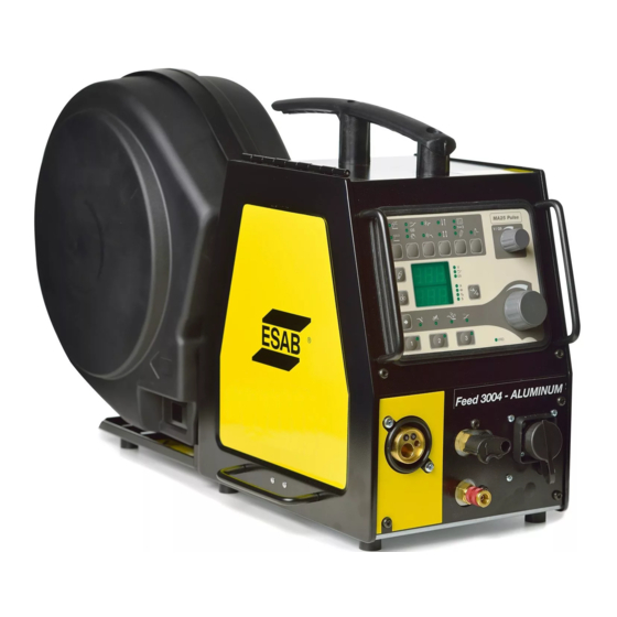
Aristo®, Origo™
Feed 3004, Feed 4804
Service manual
Valid for: serial no. 745-, 910-, 236-, 540-, 628-xxx-xxxx
0740 800 181 GB 20161005
Related Manuals for ESAB Aristo Origo Feed 3004
Summary of Contents for ESAB Aristo Origo Feed 3004
- Page 1
Aristo®, Origo™ Feed 3004, Feed 4804 Service manual Valid for: serial no. 745-, 910-, 236-, 540-, 628-xxx-xxxx 0740 800 181 GB 20161005… -
Page 2: Table Of Contents
FAULT CODES ………………..24 Fault log………………….Summary of fault codes…………….Fault code description ……………… SERVICE INSTRUCTIONS…………….27 What is ESD? ………………..Service aid ………………… SPARE PARTS ………………..29 Rights reserved to alter specifications without notice. 0740 800 181 © ESAB AB 2016…
-
Page 3: Read This First
European standards IEC/EN 60974-5. On completion of service or repair work, it is the responsibility of the person(s) performing the work to ensure that the product still complies with the requirements of the above standard. 0740 800 181 — 3 — © ESAB AB 2016…
-
Page 4: Introduction
INTRODUCTION INTRODUCTION The Feed 3004 and Feed 4804 wire feed units are intended for use with power sources equipped with CAN bus communication. 0740 800 181 — 4 — © ESAB AB 2016…
-
Page 5: Wiring Diagram
Socket connectors. 13YV1 Solenoid valve. CAUTION! STATIC ELECTRICITY can damage circuit boards and electronic components. • Observe precautions for handling electrostatic sensitive devices. • Use proper static-proof bags and boxes. 0740 800 181 — 5 — © ESAB AB 2016…
-
Page 6: Feed 3004, Feed 4804
WIRING DIAGRAM Feed 3004, Feed 4804 0740 800 181 — 6 — © ESAB AB 2016…
- Page 7
WIRING DIAGRAM 0740 800 181 — 7 — © ESAB AB 2016… -
Page 8: Technical Data
MIG/MAG welding MIG/MAG welding max pressure 0.5 MPa ( 5 bar) 0.5 MPa ( 5 bar) Coolant ESAB’s ready mixed coolant ESAB’s ready mixed coolant max pressure 0.5 MPa ( 5 bar) 0.5 MPa ( 5 bar) Maximum permissible load at…
-
Page 9: Description Of Operation
Control panel U6 The MA23 panel, with knobs for settings of voltage / wire feed speed / current. Other settings by push-buttons, with corresponding symbols on the display panel. Control panel MA23 0740 800 181 — 9 — © ESAB AB 2016…
-
Page 10: 13Ap1 Control Board
Non configured board, must be configured by ESAT. • Configured for Feed 3004 with machine ID 8 • Configured for Feed 3004 with machine ID 37 • Configured for Feed 4804 0740 800 181 — 10 — © ESAB AB 2016…
-
Page 11: 13Ap1:1 Power Supply
The +15 V is monitored by the processor and potential divider R152/R153. If the 15 V supply drops below 13 V or exceeds 17 V, the MMC panel displays fault code 8. This fault does not, however, disable any functions. 0740 800 181 — 11 — © ESAB AB 2016…
-
Page 12: 13Ap1:2 Start / Stop
13AP1:3 Gas valve The gas valve is controlled by the microprocessor. In normal operation the gas valve opens when the start signal is activated by the welding torch switch. 0740 800 181 — 12 — © ESAB AB 2016…
-
Page 13: 13Ap1:4 Motor Driving / Braking
Wire feed is stopped if the feed speed deviates from the set speed by more than 1.5 m/min for more than 5.1 seconds. The MMC panel displays fault code 11. 0740 800 181 — 13 — © ESAB AB 2016…
-
Page 14: 13Ap1:5 Pulse Generator Input
25 m/min. 13AP1:6 Monitoring the cooling water connection The wire feed unit with water connection is equipped with a detection system ELP (ESAB Logic Pump) which checks that the water hoses are connected. When connecting a water-cooled welding torch, the water pump starts.
-
Page 15: 13Ap1:7 Monitoring Wire And Gas
Although the welding power source supplies a +12 V power supply to the MMC panel, this is not used on circuit board 13AP1. 0 V on the circuit board is connected to 0 V in the MMC panel. 0740 800 181 — 15 — © ESAB AB 2016…
-
Page 16: 13Ap1:9 Arc Voltage Sensing
13AP1:9 Arc voltage sensing In order to avoid spurious volt drops when measuring the welding arc voltage, the power source senses the arc voltage via the filler wire and the feeder unit motor. 0740 800 181 — 16 — © ESAB AB 2016…
-
Page 17: 13Ap1:10 Push Pull & I/O
Terminals D, J, X and G and are used for the manual push pull, mechanized push pull, MiggyTrack and RailTrack options: see section «CAN adapter options». Terminal BA is for present not used for any standard options. 0740 800 181 — 17 — © ESAB AB 2016…
-
Page 18: 13Ap1 Component Positions
DESCRIPTION OF OPERATION 13AP1 Component positions Control board 0487 187 88x with print number 487186-001 0740 800 181 — 18 — © ESAB AB 2016…
- Page 19
DESCRIPTION OF OPERATION Control board 0487 187 8xx with print number 487186-002 0740 800 181 — 19 — © ESAB AB 2016… -
Page 20: Can Adapter Option
In position A the control panel is active and the external controls inactive. If the wire feeder is controlled by an U8, switch 13S2 has to be in position B. Then external or internal control can be selected by the U8. 0740 800 181 — 20 — © ESAB AB 2016…
-
Page 21: Welding Gun With Pull Motor
Then external or internal control of the wire feed speed can be selected by the U8. Pull motor option without wire feed speed adjustment. 0459 020 883 This option includes connectors 13XS25, 13XS20 and wires 1389, 1390. Circuit board layout, CAN adapter and filter board 0740 800 181 — 21 — © ESAB AB 2016…
-
Page 22: Connection Instructions
DESCRIPTION OF OPERATION Connection instructions Wire feeder with built-in control panel Wire feeder controlled by U8, NOTE: the switch must be in position B. 0740 800 181 — 22 — © ESAB AB 2016…
-
Page 23: Remote Controls
REMOTE CONTROLS REMOTE CONTROLS A number of remote control units can be connected to the wire feeders, these are described in a separate service manual. 0740 800 181 — 23 — © ESAB AB 2016…
-
Page 24: Fault Codes
Lost contact with the wire feed unit Lost contact with the power source Memory error in data memory Memory allocation error Transmitter buffer overflow Receiver buffer overflow Program operating fault 0ut of wire 0740 800 181 — 24 — © ESAB AB 2016…
-
Page 25: Fault Code Description
The wire feed speed differs from the set value by more than 1.5 m/min for more than 3 seconds. This fault stops the wire feed. After a period of 5 seconds, restart is permitted. 0740 800 181 — 25 — © ESAB AB 2016…
- Page 26
Stack overflow The program execution does not work. This fault should never occur in reality: the fault code is intended as an aid during development work. Contact ESAB if the fault does occur. No gas flow Gas flow is too low. -
Page 27: Service Instructions
Work surfaces, carts and containers must be conductive and grounded. Use only antistatic packaging materials. Overall, handling of ESD-sensitive devices should be minimized to prevent damage. 0740 800 181 — 27 — © ESAB AB 2016…
-
Page 28: Service Aid
The software update is made from a PC, it has to be managed by a trained serviceman. For this a PC program called ESAT, ESAB Software Administration Tool, is needed. The PC is connected to the welding equipment by a cable connector and a CAN reader. From the ESAT it is possible to update the software.
-
Page 29: Spare Parts
SPARE PARTS The spare parts list is published in a separate document that can be downloaded from the Internet: www.esab.com Filename Product 0459 839 017 Feed 3004 and Feed 4804 0740 800 181 — 29 — © ESAB AB 2016…
- Page 30
ESAB subsidiaries and representative offices Europe THE NETHERLANDS North and South America SOUTH KOREA ESAB Nederland B.V. ESAB SeAH Corporation AUSTRIA Amersfoort ARGENTINA Kyungnam ESAB Ges.m.b.H Tel: +31 33 422 35 55 CONARCO Tel: +82 55 269 8170 Vienna-Liesing Fax: +31 33 422 35 44…
Подождите не меньше 5 минут после отключения питания и отсоединения шнура от сети перед тем, как открыть пластину блока управления. Прикосновение к деталям, находящимся под высоким напряжением, может привести к несчастному случаю.

Если произойдет нарушение работы машины, послышится жужжащий звук, и в окне дисплея появится код ошибки. Чтобы удалить причину нарушения работы, выполните указанную в таблице процедуру.
| Код | Причина | Способ устранения |
| Е-13 | Неправильно подсоединен коннектор машины | Отключите питание и проверьте, отсоединены ли коннекторы Р3. |
| Е-20 | Проблема с остановкой мотора машины или ошибка с подсоединением синхронизатора. | Отключите питание, а затем поверните шкив машины, чтобы проверить, запирается ли машина. Проверьте соединение синхронизатора. Убедитесь, что отсоединены коннекторы Р11, Р12 и Р13. |
| Е-21 | Ошибка в работе мотора машины. | Отключите питание и проверьте исправность соединения заземления. |
| Е-30 | Во время установки коэффициента увеличения произошел выход за пределы возможной области пошива. | Нажмите переключатель RESET, а затем снова установите коэффициент увеличения. |
| Е-31 | Рисунок стежков находит на область пошива, когда активно ограничение области. | Нажмите переключатель RESET, а затем переустановите переключатели памяти «30» и «31» или коэффициент увеличения. |
| Е-32 | Формат данных программы пользователя (% или мм) не соответствует установкам DIP-переключателя А-6. | После изменения установки DIP-переключателя А-6, удалите все данные из памяти. (См. «10-16. Удаление всех данных из памяти»). |
| Е-40 | Длина стежка превышает 10мм | Нажмите переключатель RESET, а затем снова установите коэффициент увеличения. |
| Е-41 | Ошибка в данных пошива. | При программировании новых данных пошива повторите всю процедуру сначала. |
| Е-42 | Указан неправильно номер программы. | Нажмите переключатель RESET и укажите правильный номер. |
| Е-50 | Иглодержатель не останавливается при подъеме иглы. | Поверните шкив так, чтобы указатель поравнялся с верхним положением иглы. (см. раздел «10-12. Настройка верхнего положения остановки иглы».) Проверьте натяжение клиновидного приводного ремня. (См. раздел «3-14. Установка клиновидного приводного ремня»). |
| Е-60 | Прижим не опустился. |
См. раздел «16. Устранение неисправностей». Отключите питание и проверьте соединение коннектора Р1 датчика прижима. |
| Е-61 | Прижим не может быть поднят. | |
| Е-62 | Прижим не поднят. | |
| Е-63 | Прижим не может быть опущен. | |
| Е-64* | Прижимная лапка не закрывается. | |
| Е-70 | Охлаждающий вентилятор не работает. | Отключите питание, а затем проверьте, не засорился ли вентилятор обрывками ниток. |
| Е-80 | Мотор PROM вставлен неправильно. | Отключите питание и проверьте. |
| Е-81 | Ножной переключатель нажат, когда было включено питание. | Отключите питание и проверьте. |
| Е-82 | Переключатель панели управления был нажат во время включения питания. | Отключите питание и проверьте панель управления. Проверьте шнуры панели. |
| Е-90 | Падение напряжения питания, или питание было включено снова сразу после выключения. | Отключите питание и проверьте напряжение на входе. После выключения питания подождите 3 секунды или больше перед тем, как снова его включить. (см. «10-15. Проверка напряжения на входе.) |
| Е-91 | Повышение напряжения питания. | Отключите питание и проверьте напряжение на входе. (См. «10-15. Проверка напряжения на входе»). |
| Код | Причина | Способ устранения |
| Е-А0 | Не может быть определено начальное положение (нарушение работы датчика начального положения), или нарушение в подключении питания. | Отключите питание и проверьте соединение коннектора Р1 датчика начального положения. |
| Е-b0 | Вы попытались изменить номер программы, когда DIP-переключатель А-8 был установлен на ON. | Нажмите переключатель RESET.
Установите DIP-переключатель А-8 на OFF перед тем как изменить номер программы. |
| Е-d0 | Теплоотвод цепи панели управления перегрелся. | Отключите питание и почистите отверстия для воздуха в блоке. |
| Е-E0 | Неправильная работа EEPROM (нарушение работы главной цепи). | Отключите питание, а затем снова включите. Если ошибка появится снова, обратитесь к квалифицированному специалисту по обслуживанию машины. |
| Е-E1 | Порча данных EEPROM, или была обновлена версия PROM. | Нажмите переключатель RESET, чтобы обнулить ошибку. Однако данные (переключатели памяти, дисплей и программы пользователя) будут обнулены или установлены в исходное состояние. |
| Е-E2 | Порча данных EEPROM управления информацией. | Нажмите переключатель RESET, чтобы обнулить ошибку. однако данные (переключатели памяти, дисплей и программы пользователя) будут установлены в исходное состояние. |
| Е-F0 | Короткое замыкание цепи соленоида (нарушение работы главной цепи), или не работает реле питания (нарушение подачи питания). | Отключите питание и вызовите квалифицированного специалиста по обслуживанию машин. |
| Е-F1 | Плохое соединения кабеля между цепью подачи питания и главной цепью. | Отключите питание и проверьте, отсоединены ли коннекторы Р16. |
| Е-F2 | Обнаружение неправильного тока в цепи подачи питания. | Отключите питание и вызовите квалифицированного специалиста по обслуживанию машины. |
Ошибки, появляющиеся при использовании дополнительного оборудования
| Код | Причина | Способ устранения |
| Е-10 | Был нажат переключатель аварийной остановки. | Поверните переключатель аварийной остановки EMERGENCY STOP по часовой стрелке, чтобы отменить запирание, а затем нажмите переключатель RESET, чтобы обнулить ошибку. |
| Е-11 | Во время шитья был нажат переключатель аварийной остановки. | Поверните переключатель аварийной остановки EMERGENCY STOP по часовой стрелке, чтобы отменить запирание, а затем нажмите переключатель RESET, чтобы обнулить ошибку. Вы можете нажать переключатель STEP BACK /шаг назад/, чтобы повторить пошив. |
| Е-12 | Переключатель аварийной остановки непрерывно нажат, или ошибка соединения переключателя аварийной остановки. | Отключите питание и проверьте. |
| Е-14 | Определен разрыв нити. | Поверните переключатель аварийной остановки EMERGENCY STOP по часовой стрелке, чтобы отменить запирание, а затем нажмите переключатель RESET, чтобы обнулить ошибку. Вы можете нажать переключатель STEP BACK /шаг назад/, чтобы повторить пошив. |

Указатель сегментный светодиодный алфавит
Либо программа, либо микра оптосвязи вышла из строя на одном из ID.
Тут вариантов немного.
Есть ещё мелкий процент (0.1%) помехи с силы, но я за более чем 20 лет ремонта и работы в СЦ Эсаба, раз только с таким столкнулся.
Изменено 23 августа, 2021 пользователем tehsvar