
Силовой источник 1…..50
Логика MIG 51…..100
Доступ Кривой 101…..130
Интерфейс Робота 131…..150
MIG/TIG Устройство 151…..200
Интерфейс пользавателя 201…..250
Другие 0…..999
Err 2: Силовой источник под напряжением (новый пуск)
Err 3: Силовое исходное перенапряжение (новый пуск)
Err 4: Силовой источник перегрет.
Err 5: Водяная тревога устройства.
Err 11: Два устройства имеют тот же адрес на системной шине.
Err 12: Ошибка данных на связи (2)
Err 13: *Цензура* неправильного семейства FastMIG связанного.
Err 14: Проблема связи Данных между силовым источником и вспомогательным устройством.
Err 15: Силовая исходная программа / обновление метода проблемы.
Err 21: Силовая исходная управляющая карта +5 aux V. Напряжение слишком низкий уровень.
Err 22: Силовая исходная управляющая карта +15 aux V. Напряжение слишком низкий уровень.
Err 23: Временно силовое исходное перенапряжение.
Err 31: Силовая исходная ошибка калибровки. Сваривать только возможно со значением по умолчанию.
Err 54: Нет связи с источником питания. Возможно неисправный кабель/разъем..
Err 55: Сварка запрещена(конфигурация / системной шине резервирована)
Err 61: Нет связи с водоохладителем..
Err 153: Перегрев холодной жидкости сварочного рукава.
Err 154: Двигатель подачи проволоки перегружен выше предела.
Возможно засорена спираль или сильний изгиб сварочного рукава.
Err 155: Перегрузка двигателя подачи проволоки. Движение (ток) двигателя слишком близкое к пределу.
Err 161: Предупреждение перегрева устройства проволочной подачи.
Err 162: Перегрузка двигателя подачи проволоки.
Err 171: Конфигурация оборудования не может обнаружится.
Err 172: Поставлен неправильный код конфигурации.
Err 173: Действие не активизировано кодом конфигурации права
Err 184: Неисправен управляющий кабель.
Err 185: Машинная программная ошибка коррекции. Неправильная программа или обновить коррекцию.
Err 201: Использование сварочного рукава PMT-предохраненного.
Err 221: Ошибка данных панели (1)
Err 222: Ошибка данных панели (2)
Err 223: Ошибка данных панели (3)
Err 224: Ошибка данных панели (4)
Err 225: Запрограммируйте обновление проблемы.
Err 241: Ошыбка памяти EEPROM
Err 251: Ошибка связи данных DLI (другое устройство в шине использует то же код=конфигурацию)
Err 251: Ошибка (2) данных DLI
Err 254: Ошибка связи данных DLI ( плохой разъем или кабель)
Err 255: Ошибка связи данных DLI
(программная проблема коррекции, может быть неправильная программная версия и т.п.).
Err 999: Неопознанная ошибка (система послала сообщение ошибки не идентифицированное панелью)
Источник: https://krb1-elektrik.narod.ru
The wire inch switch starts the wire feed motor without starting the power
source and without opening the gas valve.
3.11. GAS PURGE SWITCH
The gas purge switch opens the gas valve without starting the wire feed
motor and the power source.
3.12. FEED 420R ERROR CODES
By every start possible error states in equipment are checked. If an error state is found, the error
in question is shown with an E text appearing in the panel display.
Here are some error codes:
E.09:
Overloading of wire feed motor, which can be e.g. due to blocked wire guide tube of
gun, or too sharply bent gun cable.
E.12:
The welding is prevented because the shielding gas control of the gas guard GG 400
has released.
The error codes disappear by following start, if reason of the error code is eliminated.
4.
ACCESSORIES
4.1.
SYNCHRONIZING UNIT SYNC 400
By means of Sync 400 you can connect the push-pull gun to the Feed 420R wire feeding control
unit. Push-pull gun is most commonly used for feeding of aluminium wires. Push-pull gun
enables extending the working radius up to 10 m. Sync 400 is mounted into electronics case of
Feed 420R. Mounting of Sync 400 is described in the mounting instructions delivered with the
unit.
4.2.
GAS GUARD GG 400
With gas guard accessory you can prevent weld defects due to lacking or wrong fl ow of
shielding gas. Functions of gas guard are as follows:
– Prevention of welding if the gas pressure is not suffi cent on the wire feeder unit.
– Stopping of welding if shielding gas pressure disappears during welding.
– When gas guard has prevented welding, error message E.12 appears on welding panel
displays.
– Shielding gas fl ow meter / regulator. Regulation range 5-25 l/min. Display is calibrated for
shielding gas Ar CO
(75 % Ar, 25 % CO
2
4.3.
HANGING ONTO BOOM
The lift hook is mounted to handle of Feed 420R. The position depends on the lift hook hole
position.
16 – Kempomig Feed 420R, 120R / 0429
)
2
©
COPYRIGHT KEMPPI OY
Силовой источник 1…..50
Логика MIG 51…..100
Доступ Кривой 101…..130
Интерфейс Робота 131…..150
MIG/TIG Устройство 151…..200
Интерфейс пользавателя 201…..250
Другие 0…..999
Err 2: Силовой источник под напряжением (новый пуск)
Err 3: Силовое исходное перенапряжение (новый пуск)
Err 4: Силовой источник перегрет.
Err 5: Водяная тревога устройства.
Err 11: Два устройства имеют тот же адрес на системной шине.
Err 12: Ошибка данных на связи (2)
Err 13: *Цензура* неправильного семейства FastMIG связанного.
Err 14: Проблема связи Данных между силовым источником и вспомогательным устройством.
Err 15: Силовая исходная программа / обновление метода проблемы.
Err 21: Силовая исходная управляющая карта +5 aux V. Напряжение слишком низкий уровень.
Err 22: Силовая исходная управляющая карта +15 aux V. Напряжение слишком низкий уровень.
Err 23: Временно силовое исходное перенапряжение.
Err 31: Силовая исходная ошибка калибровки. Сваривать только возможно со значением по умолчанию.
Err 54: Нет связи с источником питания. Возможно неисправный кабель/разъем..
Err 55: Сварка запрещена(конфигурация / системной шине резервирована)
Err 61: Нет связи с водоохладителем..
Err 153: Перегрев холодной жидкости сварочного рукава.
Err 154: Двигатель подачи проволоки перегружен выше предела.
Возможно засорена спираль или сильний изгиб сварочного рукава.
Err 155: Перегрузка двигателя подачи проволоки. Движение (ток) двигателя слишком близкое к пределу.
Err 161: Предупреждение перегрева устройства проволочной подачи.
Err 162: Перегрузка двигателя подачи проволоки.
Err 171: Конфигурация оборудования не может обнаружится.
Err 172: Поставлен неправильный код конфигурации.
Err 173: Действие не активизировано кодом конфигурации права
Err 184: Неисправен управляющий кабель.
Err 185: Машинная программная ошибка коррекции. Неправильная программа или обновить коррекцию.
Err 201: Использование сварочного рукава PMT-предохраненного.
Err 221: Ошибка данных панели (1)
Err 222: Ошибка данных панели (2)
Err 223: Ошибка данных панели (3)
Err 224: Ошибка данных панели (4)
Err 225: Запрограммируйте обновление проблемы.
Err 241: Ошыбка памяти EEPROM
Err 251: Ошибка связи данных DLI (другое устройство в шине использует то же код=конфигурацию)
Err 251: Ошибка (2) данных DLI
Err 254: Ошибка связи данных DLI ( плохой разъем или кабель)
Err 255: Ошибка связи данных DLI
(программная проблема коррекции, может быть неправильная программная версия и т.п.).
Err 999: Неопознанная ошибка (система послала сообщение ошибки не идентифицированное панелью)
Источник: https://krb1-elektrik.narod.ru
- Manuals
- Brands
- Kemppi Manuals
- Welding System
- FastMig KM500
- Operating manual
-
Contents
-
Table of Contents
-
Troubleshooting
-
Bookmarks
Quick Links
FastMig
KM 300, 400, 500
Operating manual
Käyttöohje
Bruksanvisning
Bruksanvisning
Brugsanvisning
Gebrauchsanweisung
Gebruiksaanwijzing
Manuel d’utilisation
Manual de instrucciones
Instrukcja obsługi
Инструкции по эксплуатации
操作手册
Manual de utilização
Manuale d’uso
EN
FI
SV
NO
DA
DE
NL
FR
ES
PL
RU
ZH
PT
IT
Related Manuals for Kemppi FastMig KM 300
Summary of Contents for Kemppi FastMig KM 300
- Page 1
FastMig KM 300, 400, 500 Operating manual Käyttöohje Bruksanvisning Bruksanvisning Brugsanvisning Gebrauchsanweisung Gebruiksaanwijzing Manuel d’utilisation Manual de instrucciones Instrukcja obsługi Инструкции по эксплуатации 操作手册 Manual de utilização Manuale d’uso… - Page 3
OPERATING MANUAL English… - Page 4
CONTENTS Johdanto ………………Yleistä… - Page 5
This operating manual contains important information on the use, maintenance and safety of your Kemppi product. The technical specifications of the equipment can be found at the end of the manual. Please read the manual carefully before using the equipment for the first time. For your own safety and that of your working environment, pay particular attention to the safety instructions in the manual. - Page 6
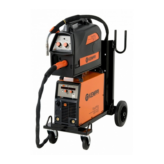
Introduction The FastMig KM-series power sources 300, 400, and 500 are MIG power sources designed for demanding professional use in the three-phase network. The power source has a control panel that allows ready control of the functions of the power source and the wire feeder. Overview of the power source Front view Rear view… -
Page 7: Installation
WARNING: This equipment does not comply with IEC 61000-3-12. If it is connected to a public low voltage system, it is the responsibility of the installer or user of the equipment to ensure, by consultation with the distribution network operator if necessary, that the equipment may be connected. © Kemppi Oy / 1152…
-
Page 8: Connection To Mains
Connection to mains FastMig KM power sources are connected to the 400-V three-phase network using the mains cable supplied with the machine. The machine is equipped with a five-metre mains cable that does not have a plug. Before use, check the mains cable and install a mains plug. If the cable does not comply with the local electrical regulations, replace it with a compliant cable.
-
Page 9: Machine Use
Section 4, ‘Troubleshooting’ . If the failure cannot be eliminated, turn off the machine, and turn it on again. If the failure persists, write down any fault code that may be shown on the display and contact authorised Kemppi service agent.
-
Page 10: Use Of The Control Panel
Use of the control panel The control panel is used for controlling and monitoring the operation of the power source and the wire feeder. The buttons are used for adjusting functions. The displays and indicators reflect the operating modes of the machine. 3.3.1 Starting of the control panel • When you start the power source with the main switch (A2), the control panel remains in OFF mode and the wire feeder is not operational.
-
Page 11: Setting Of The Mig Operating Mode
P2. The value you selected is recorded in the control panel memory. • Exit the set-up menu by pressing button P7 again and holding for at least five seconds or by briefly pressing the control panel start button (P1). © Kemppi Oy / 1152…
- Page 12
The table below lists the operation parameters and their possible values. Name of Name Parameter Factory Description parameter displayed values values Pre Gas Time 0.0 – 9.9 s 0.1 s Pre-welding gas time in seconds Post Gas Time Aut, 0.1 – 32.0 s Post-welding gas time in seconds or automatically according to welding current 1 s / 100 A (Aut) -
Page 13: Troubleshooting
Therefore, repeat steps 2 – 11 and then device is ready for welding. TROUBLESHOOTING In the event of a failure of the machine, contact an authorised Kemppi service agent. Before taking your unit for servicing, check the list below.
-
Page 14: Machine Error Codes
Check the trigger’s leads. Other error codes: The machine can show codes not listed here. In the event of an unlisted code appearing, contact an authorised Kemppi service agent and report the error code shown. FastMig 300, 400, 500…
-
Page 15: Power Source
Remember that the machine may be repaired only by an electrical contractor or installer NOTE! authorised to perform such operations. Regular maintenance Authorised Kemppi service agents perform regular maintenance by agreement. Tasks included in regular maintenance: • Cleaning of equipment. • Inspection and maintenance of the welding gun.
-
Page 16: Disposal Of The Machine
The owner of the equipment is obliged to deliver a decommissioned unit to a regional collection centre, per the instructions of local authorities or a Kemppi representative. By applying this European Directive you will improve the environment and human health.
- Page 17
400 V, -15 … +20% 400 V, -1 … +20% 400 V, -15 … +20% Voltage supply for cooling unit 1~ 400 V AC 1~ 400 V AC 1~ 400 V AC * See paragraph 2.2. © Kemppi Oy / 1152… - Page 18
78681 EPONE CEDEX myynti.fi@kemppi.com info.ru@kemppi.com FRANCE Tel +33 1 30 90 04 40 KEMPPI SVERIGE AB KEMPPI, TRADING (BEIJING) COMPANY, Telefax +33 1 30 90 04 45 LIMITED Box 717 sales.fr@kemppi.com Room 420, 3 Zone, Building B, S-194 27 UPPLANDS VÄSBY No.12 Hongda North Street,…
- Manuals
- Brands
- Kemppi Manuals
- Welding System
- FastMig KM500
- Operating manual
-
Contents
-
Table of Contents
-
Troubleshooting
-
Bookmarks
Quick Links
FastMig
KM 300, 400, 500
Operating manual
Käyttöohje
Bruksanvisning
Bruksanvisning
Brugsanvisning
Gebrauchsanweisung
Gebruiksaanwijzing
Manuel d’utilisation
Manual de instrucciones
Instrukcja obsługi
Инструкции по эксплуатации
操作手册
Manual de utilização
Manuale d’uso
EN
FI
SV
NO
DA
DE
NL
FR
ES
PL
RU
ZH
PT
IT
Related Manuals for Kemppi FastMig KM 300
Summary of Contents for Kemppi FastMig KM 300
- Page 1
FastMig KM 300, 400, 500 Operating manual Käyttöohje Bruksanvisning Bruksanvisning Brugsanvisning Gebrauchsanweisung Gebruiksaanwijzing Manuel d’utilisation Manual de instrucciones Instrukcja obsługi Инструкции по эксплуатации 操作手册 Manual de utilização Manuale d’uso… - Page 3
OPERATING MANUAL English… - Page 4
CONTENTS Johdanto ………………Yleistä… - Page 5
This operating manual contains important information on the use, maintenance and safety of your Kemppi product. The technical specifications of the equipment can be found at the end of the manual. Please read the manual carefully before using the equipment for the first time. For your own safety and that of your working environment, pay particular attention to the safety instructions in the manual. - Page 6
Introduction The FastMig KM-series power sources 300, 400, and 500 are MIG power sources designed for demanding professional use in the three-phase network. The power source has a control panel that allows ready control of the functions of the power source and the wire feeder. Overview of the power source Front view Rear view… -
Page 7: Installation
WARNING: This equipment does not comply with IEC 61000-3-12. If it is connected to a public low voltage system, it is the responsibility of the installer or user of the equipment to ensure, by consultation with the distribution network operator if necessary, that the equipment may be connected. © Kemppi Oy / 1152…
-
Page 8: Connection To Mains
Connection to mains FastMig KM power sources are connected to the 400-V three-phase network using the mains cable supplied with the machine. The machine is equipped with a five-metre mains cable that does not have a plug. Before use, check the mains cable and install a mains plug. If the cable does not comply with the local electrical regulations, replace it with a compliant cable.
-
Page 9: Machine Use
Section 4, ‘Troubleshooting’ . If the failure cannot be eliminated, turn off the machine, and turn it on again. If the failure persists, write down any fault code that may be shown on the display and contact authorised Kemppi service agent.
-
Page 10: Use Of The Control Panel
Use of the control panel The control panel is used for controlling and monitoring the operation of the power source and the wire feeder. The buttons are used for adjusting functions. The displays and indicators reflect the operating modes of the machine. 3.3.1 Starting of the control panel • When you start the power source with the main switch (A2), the control panel remains in OFF mode and the wire feeder is not operational.
-
Page 11: Setting Of The Mig Operating Mode
P2. The value you selected is recorded in the control panel memory. • Exit the set-up menu by pressing button P7 again and holding for at least five seconds or by briefly pressing the control panel start button (P1). © Kemppi Oy / 1152…
- Page 12
The table below lists the operation parameters and their possible values. Name of Name Parameter Factory Description parameter displayed values values Pre Gas Time 0.0 – 9.9 s 0.1 s Pre-welding gas time in seconds Post Gas Time Aut, 0.1 – 32.0 s Post-welding gas time in seconds or automatically according to welding current 1 s / 100 A (Aut) -
Page 13: Troubleshooting
Therefore, repeat steps 2 – 11 and then device is ready for welding. TROUBLESHOOTING In the event of a failure of the machine, contact an authorised Kemppi service agent. Before taking your unit for servicing, check the list below.
-
Page 14: Machine Error Codes
Check the trigger’s leads. Other error codes: The machine can show codes not listed here. In the event of an unlisted code appearing, contact an authorised Kemppi service agent and report the error code shown. FastMig 300, 400, 500…
-
Page 15: Power Source
Remember that the machine may be repaired only by an electrical contractor or installer NOTE! authorised to perform such operations. Regular maintenance Authorised Kemppi service agents perform regular maintenance by agreement. Tasks included in regular maintenance: • Cleaning of equipment. • Inspection and maintenance of the welding gun.
-
Page 16: Disposal Of The Machine
The owner of the equipment is obliged to deliver a decommissioned unit to a regional collection centre, per the instructions of local authorities or a Kemppi representative. By applying this European Directive you will improve the environment and human health.
- Page 17
400 V, -15 … +20% 400 V, -1 … +20% 400 V, -15 … +20% Voltage supply for cooling unit 1~ 400 V AC 1~ 400 V AC 1~ 400 V AC * See paragraph 2.2. © Kemppi Oy / 1152… - Page 18
78681 EPONE CEDEX myynti.fi@kemppi.com info.ru@kemppi.com FRANCE Tel +33 1 30 90 04 40 KEMPPI SVERIGE AB KEMPPI, TRADING (BEIJING) COMPANY, Telefax +33 1 30 90 04 45 LIMITED Box 717 sales.fr@kemppi.com Room 420, 3 Zone, Building B, S-194 27 UPPLANDS VÄSBY No.12 Hongda North Street,…
CONTENTS
1.
PREFACE……………………………………………………………………………
3
1.1
General……………………………………………………………………………………………………………………….
3
1.2
Introduction………………………………………………………………………………………………………………
4
2.
INSTALLATION…………………………………………………………………..
5
2.1
Positioning of the machine…………………………………………………………………………………….
5
2.2
Distribution network……………………………………………………………………………………………….
5
2.3
Connection to mains……………………………………………………………………………………………….
5
2.4
Welding and earthing cables………………………………………………………………………………….
6
3.
MACHINE USE……………………………………………………………………
6
3.1
Starting of the power source………………………………………………………………………………….
6
3.2
Front panel indicators……………………………………………………………………………………………..
6
3.3
Use of the control panel………………………………………………………………………………………….
7
3.3.1 Starting of the control panel……………………………………………………………………………….
7
3.3.2
Displays……………………………………………………………………………………………………………..
7
3.3.3
Control knobs…………………………………………………………………………………………………….
7
3.3.4 Adjustment of MIG dynamics (arc force)………………………………………………………………
8
3.3.5
Gas test………………………………………………………………………………………………………………
8
3.3.6
Wire feed test……………………………………………………………………………………………………..
8
3.3.7 Selection of liquidor gas-cooled MIG gun…………………………………………………………..
8
3.3.8 Retrieval of weld data…………………………………………………………………………………………
8
3.3.9 Selection of control panel……………………………………………………………………………………
8
3.3.10 Setting of the MIG operating mode……………………………………………………………………..
8
3.3.11 Setting of operation parameters………………………………………………………………………….
9
3.3.12 Calibration of the wire feed speed……………………………………………………………………..
10
4.
TROUBLESHOOTING………………………………………………………..
10
4.1
Overload (yellow indicator lit)………………………………………………………………………………
10
4.2
Control cable connector fuse……………………………………………………………………………….
10
4.3
Electric network overvoltage or undervoltage………………………………………………….
11
4.4
Missing phase in the electric network………………………………………………………………..
11
4.5
Machine error codes………………………………………………………………………………………………
11
5.
SERVICE…………………………………………………………………………..
12
5.1
Cables……………………………………………………………………………………………………………………….
12
5.2
Power source……………………………………………………………………………………………………………
12
5.3
Regular maintenance…………………………………………………………………………………………….
12
5.4
Disposal of the machine………………………………………………………………………………………..
13
6.
ORDERING NUMBERS………………………………………………………
13
7.
TECHNICAL SPECIFICATIONS……………………………………………
13
8.
WARRANTY POLICY…………………………………………………………
14
Important to remember:
Guidesimo.com webproject is not a service center of Kemppi trademark and does not carries out works for diagnosis and repair of faulty Kemppi FastMig KM 400 MVU equipment. For quality services, please contact an official service center of Kemppi company. On our website you can read and download documentation for your Kemppi FastMig KM 400 MVU device for free and familiarize yourself with the technical specifications of device.
Welding System Devices:
-
Lincoln Electric AIR VANTAGE IM10041
AIR VANTAGE 500 CUMMINSOPERATOR’S MANUALIM10041November, 2009Safety Depends on YouLincoln arc welding and cuttingequipment is designed and builtwith safety in mind. However,your overall safety can beincreased by proper installation …and thoughtful operation on yourpart. DO NOT INSTALL, OPE R-ATE OR REPAIR THIS EQUIP-MENT WITHOUT READINGTHIS MANUAL AND THE SAFE-TY PRECAUTIONS CONTAINEDTHROUGHOU …
AIR VANTAGE IM10041 Welding System, 54
-
ESAB Super Bantam 225 AC
Fonte de energia para solda com eletrodosrevestidos em corrente alternada (AC)Fonte de energia para solda com eletrodosrevestidos em corrente alternada (AC)SUPER BANTAM225 ACSUPER BANTAM225 ACManual de InstruçõesRef.: Super Bantam 225 AC 60Hz0401202 …
Super Bantam 225 AC Welding System, 32
-
Lincoln Electric VANTAGE SVM178-B
SVM178-BApril, 2011Safety Depends on YouLincoln arc welding and cuttingequipment is designed and builtwith safety in mind. However,your overall safety can beincreased by proper installation. . . and thoughtful operation onyour part. DO NOT INSTALL,OPERATE OR REPAIR THISEQUIPMENT WITHOUT READ-ING THIS MANUAL AND THESAFETY PRECAUTIONS CON-TAINED THROUGHO …
VANTAGE SVM178-B Welding System, 278
-
omisa HST 300 Smart
HST 300 SmartVersione Febbraio 2020O.M.I.S.A. S r lVia Verga 9/1120845 Sovico (MB) +39 039 2323028 [email protected] http://www.omisa.itManuale d’uso • User’s ManualBedienungsanleitung • Manual de instrucciones …
HST 300 Smart Soldering Gun, 91
-
CEA TREO 1800 Synergic MIG-MAG
TREO 1800synergicENOperator’s manualREAD CAREFULLY1020HA90B-EN-12/2014 SN — XN xxxxxxCEA COSTRUZIONI ELETTROMECCANICHE ANNETTONI S.p.A.C.so E. Filiberto, 27 — 23900 Lecco — ItalyTel. ++39.0341.22322 — Fax ++39.0341.422646Cas. Post. (P.O.BOX) 205e-mail: [email protected] — web: www.ceaweld.com …
TREO 1800 Synergic MIG-MAG Welding System, 42
-
H&S AUTOSHOT HST201
Part # HSW-6321 Processes TIG (GTAW) Welding …
HST201 Welding System, 33
More Welding System Instructions:
- Manuals
- Brands
- Kemppi Manuals
- Welding System
- FastMig KM 400 MVU
- Operation manual
-
Contents
-
Table of Contents
-
Troubleshooting
-
Bookmarks
Quick Links
FastMig
KM 400 MVU
EN
Operating manual • English
NO
Bruksanvisning • Norsk
Related Manuals for Kemppi FastMig KM 400 MVU
Summary of Contents for Kemppi FastMig KM 400 MVU
- Page 1
FastMig KM 400 MVU Operating manual • English Bruksanvisning • Norsk… - Page 3
OPERATING MANUAL English… -
Page 4: Table Of Contents
CONTENTS PREFACE ………………General ……………………….Introduction ..
-
Page 5: Preface
This user manual contains important information on the use, maintenance, and safety of your Kemppi product. The technical specifications of the device can be found at the end of the manual. Please read the manual carefully before using the equipment for the first time.
-
Page 6: Introduction
INTRODUCTION The FastMig KM-series power source 400 is a MIG power source designed for demanding professional use in the three-phase network. The power source has a control panel that allows ready control of the functions of the power source and the wire feeder. Overview of the power source Front view Rear view…
-
Page 7: Installation
INSTALLATION POSITIONING OF THE MACHINE Place the machine on a firm, dry and level surface. Where possible, do not allow dust or other impurities to enter the machines cooling air flow. Preferably site the machine above floor level; for example on a suitable carriage unit. Notes for positioning the machine • The surface inclination should not exceed 15 degrees.
-
Page 8: Welding And Earthing Cables
Section 4, ‘Troubleshooting’ . If the failure cannot be eliminated, turn off the machine, and turn it on again. If the failure persists, write down any fault code that may be shown on the display and contact authorised Kemppi service agent.
-
Page 9: Use Of The Control Panel
USE OF THE CONTROL PANEL The control panel is used for controlling and monitoring the operation of the power source and the wire feeder. The buttons are used for adjusting functions. The displays and indicators reflect the operating modes of the machine. weld data DYNAMICS…
-
Page 10: Adjustment Of Mig Dynamics (Arc Force)
3.3.4 Adjustment of MIG dynamics (arc force) When you press button 3, you can adjust the MIG welding dynamics of the machine by means of the right-hand knob, 11. The welding dynamics setting affects the properties of the welding arc and the amount of spatter as follows: • The value 0 is the recommended basic setting.
-
Page 11: Setting Of Operation Parameters
3.3.11 Setting of operation parameters Button 9 also is used for changing welding parameters as follows: • Depress button 9 for at least five seconds. The set-up menu appears on display 2. • Select the parameter to adjust with the left-hand knob (10) so that the name of the parameter you want to adjust is shown on display 2.
-
Page 12: Calibration Of The Wire Feed Speed
At the same time, the device exits calibration mode and returns to basic operation mode. TROUBLESHOOTING In the event of a failure of the machine, contact an authorised Kemppi service agent. Before taking your unit for servicing, check the list below. OVERLOAD (YELLOW INDICATOR LIT) Two simultaneously operating fans cool the power source.
-
Page 13: Electric Network Overvoltage Or Undervoltage
ELECTRIC NETWORK OVERVOLTAGE OR UNDERVOLTAGE If the power source is used in an electric network with insufficient voltage (less than 300 V), the control features of the device are disabled automatically. The primary circuits of the power source are protected against power spikes. The product’s mains voltage range is broad enough to prevent overvoltage problems at up to 440 V (see Section 8, ‘Technical specifications’).
-
Page 14: Service
Other error codes: The machine can show codes not listed here. In the event of an unlisted code appearing, contact an authorised Kemppi service agent and report the error code shown. SERVICE The utilisation level of the power source and its working environment should be taken into consideration in planning the frequency of maintenance of the machine.
-
Page 15: Disposal Of The Machine
The owner of the equipment is obliged to deliver a decommissioned unit to a regional collection centre, per the instructions of local authorities or a Kemppi representative. By applying this European Directive you will improve the environment and human health.
-
Page 16: Warranty Policy
The proof must indicate the date of purchase and the manufacturing number of the unit to be repaired. The parts replaced under the terms of this warranty remain the property of Kemppi and must be returned to Kemppi if requested.
- Page 18
Telefax +358 3 734 8398 FRANCE e-mail: myynti.fi @kemppi.com Tel +33 1 30 90 04 40 KEMPPI, TRADING (BEIJING) COMPANY, LIMITED Telefax +33 1 30 90 04 45 KEMPPI SVERIGE AB Room 420, 3 Zone, Building B, e-mail: sales.fr@kemppi.com Box 717 No.12 Hongda North Street,…
Рекомендуемые сообщения
")
-
- Поделиться
Сварочный аппарат Kemppi X3 Power Source 400 всё было отлично, но дуга сама начала обрываться без видимых на то причин и вылетать ошибка с кодом err 006. В чём проблема??? Помогите разобраться.Спасибо.
- Цитата
Ссылка на комментарий
Поделиться на другие сайты
- Супермодератор

- Супермодератор
-
- Поделиться
повышенное напряжение на клеммах. (производитель рекомендует обратиться в сервис)
———
от себя добавлю-
1-проверьте в первую очередь целостность всего контура заземления , начиная от розетки
2-шлейф панели в месте подключения(если при регулировке показания «прыгают»).
Ссылка на комментарий
Поделиться на другие сайты

")
-
- Поделиться
повышенное напряжение на клеммах. (производитель рекомендует обратиться в сервис)
Если имеются в виду входные клеммы аппарата, (скорее всего, так и есть. Защита инвертора от перегрузки по мощности и защита от подгорания разъёмов при плохом контакте) — проверить все провода на выходе — массу, горелку, провода от инвертора до подавлки.
Изменено 28 апреля, 2019 пользователем SergDemin
Ссылка на комментарий
Поделиться на другие сайты

-
- Поделиться
Ошибка 006, это то-же то и ERR6 в аппаратах серии Мaster TIG ACDC. «Превышение выходного напряжения.»
Там это говорит о неисправности блока вторичного инвертора.
- Цитата
Ссылка на комментарий
Поделиться на другие сайты
-
- Поделиться
Вот так часто бывает. Заявиться какой нибудь новичок, поплачется о проблемах, народ начинает тут распинаться а ему и по барабану. Нет его ту и не будет ни когда. Кстати, проблема не только этого форума.
Именно по тому порой и не хочется суетится. Ну проблема, ну и что, почему бы за денежку к местным специалистам не обратиться? Ну что бы в интернете не мусорить.
Изменено 30 апреля, 2019 пользователем Sivanov
Ссылка на комментарий
Поделиться на другие сайты
- 4 месяца спустя…
-
- Поделиться
Здравствуйте. Помогите настроить данный аппарат Х3
- Цитата
Ссылка на комментарий
Поделиться на другие сайты
-
- Поделиться
Здравствуйте. Помогите настроить данный аппарат Х3
А чего там настраивать то? Простой как три рубля. Ни синергетики ни сварочных кривых. В чём проблема то?
Изменено 27 сентября, 2019 пользователем Sivanov
Ссылка на комментарий
Поделиться на другие сайты
-
- Поделиться
Настроить на вертикал . Аппарат купили для сварки вертикалов на броне 40ка вэ образная фаска .
- Цитата
Ссылка на комментарий
Поделиться на другие сайты
-
- Поделиться
Варил образец под узк вертикал , пластина 20 мм . Вот к чему я пришел : корень — скорость 2.5 , 18.9. вольт . Наполнение и облицовка , скорость 2.9 , 19 вольт . Проволока 1.2 , углекислота . Вроде нормально . Вопрос 40 с теми же режимами варить !?
- Цитата
Ссылка на комментарий
Поделиться на другие сайты

-
- Поделиться
предподогрев до100-120. корень в зависимости от разделки и зазора. далее- 3.5; 4.5; 5,5 до 6 вполне. вашими режимами я только велосипедные рамы подвариваю. температуру контролировать- не выше 350. давать остывать если что. если к тепловложению жесткие требования- тогда подача не выше 4-5. и валики не шире 20мм. и не старайтесь за мару проходов заполнить фаску( реально можно- на подаче 10-12) старайтесь толщину за один проход 2-3мм не более. это будет кошерно и благодать снизойдет на правильного сварщика. на сделке? тогда брак гнать ради денег и не спрашивать.( узк проходит- но брак 100%)
вероятно, можно и с Вашими режимами варить- до морковкиного заговенья.(долго, мучительно и малорезультативно)
Изменено 28 сентября, 2019 пользователем caro
- Цитата
Ссылка на комментарий
Поделиться на другие сайты
-
- Поделиться
Ребят, вы о чём? Х3 как я понял это аналог FastMigKM. Там есть возможность настройки только скорости подачи проволоки и напряжения. По моему даже динамикой нет возможности управлять как в КМ.
По моему это самый простой аппарат за свою цену.
Раньше помню работал на наших аппаратах. На балетке скорость проволоки а на источнике ступенчато напряжение регулировалось. И тут вроде на подобии. У него даже между источником и подающим чисто аналоговый обмен идёт.
Изменено 29 сентября, 2019 пользователем Sivanov
Ссылка на комментарий
Поделиться на другие сайты
Присоединяйтесь к обсуждению
Вы можете написать сейчас и зарегистрироваться позже.
Если у вас есть аккаунт, авторизуйтесь, чтобы опубликовать от имени своего аккаунта.
Примечание: Ваш пост будет проверен модератором, прежде чем станет видимым.
Возникающие в процессе эксплуатации автомобиля проблемы свидетельствуют о наличии неисправности в функционировании определенных его агрегатов. В работе электрических и электронных систем они проявляются в виде индикатора на приборной панели «Check Engine», который в простонародье называют просто «Чек».
Появление «чека» сигнализирует автолюбителю о необходимости проведения диагностики автомобиля как можно скорее. При наличии ELM сканера диагностика может быть проведена самостоятельно. Чтобы расшифровать код неисправности блока управления автомобилем, необходимо:
Описание ошибки P0420

Для контроля качества и эффективности его функционирования перед и после нейтрализатора устанавливаются датчики контроля уровня кислорода (лямбда-зонды) перед и после каталитического нейтрализатора.
Электронный блок управления авто (далее просто ЭБУ) при заведенном двигателе контролирует показания обоих датчиков, причем данные с первого берутся за эталон. И если превышено пороговое значение между двумя датчиками, появляется индикатор неисправности.
Условия появления индикатора кода P0420 на приборной панели следующие:
Как уже было сказано, катализатор отвечает за нейтрализацию вредных выбросов в атмосферу. Стандарт Евро-3 ввел обязательный контроль за уровнем выбросов двумя кислородными датчиками. То есть все современные автомобили, начиная от бюджетных моделей авто, вроде Шевроле Ланос и заканчивая более дорогостоящими марками, как например, Мазда 3, имеют подобную систему по умолчанию.
Как может проявляться ошибка P0420?
Ошибка P0420 прямо указывает на неисправности системы катализации и может проявляться следующим образом:
Причины возникновения ошибки P0420

Самой безобидной из всех озвученных причин можно назвать некачественный бензин, а наиболее опасной — повреждение внутренностей нейтрализатора. При этой проблеме части катализатора могут попадать в двигатель, необратимо разрушая его. В этом случае решением проблемы может быть удаление, либо замена данного узла на новый.
Дешевле всего обходится удаление катализатора, однако стоит помнить, что в таком случае автомобиль перестает соответствовать нормам выброса, установленным при производстве (чаще всего Евро-4 и выше). При удалении нейтрализатора дополнительно необходимо программная перепрошивка ЭБУ для исключения случаев возникновения ошибок от неиспользующегося второго кислородного датчика.
Каталитический нейтрализатор может приходить в негодность по следующим причинам:
Главное, что необходимо помнить при появлении кода P0420 — нет никакой гарантии, что дорогостоящая замена катализатора решит проблему.
Ведь причиной может стать банальное нарушение целостности прокладок выхлопной системы, либо неисправность датчиков кислорода.
Способы устранения ошибки P0420
Использовать описанные ниже способы можно только при отсутствии возможности обращения в специализированные станции техобслуживания. Для выявления всех причин возникновения подобной проблемы лучше обратиться к специалистам. Они при помощи специального оборудования установят и устранят все отклонения в работе узлов автомобиля, отвечающих за функционирование системы выхлопа газов.
Не стоит доверять советам из интернета вроде «почистите дроссельную заслонку». Системы выпуска отработавших газов — довольно сложный механизм, включающий в себя не только механические, но и электрические компоненты, некорректная работа которых может не только вызывать появление неисправности P0420, но и негативно влиять на состояние самого главного узла автомобиля — двигателя.
Самыми простыми в исполнении будут следующие советы для выявления причин возникновения кода P0420:
Указанные выше советы и рекомендации будут полезны при работе со всеми современными отечественными и зарубежными авто, такими, как:
Однако в любом случае рекомендуется работы по диагностике, выявлению и устранению неисправностей, связанных с системой выхлопа, производить на специализированных станциях, во избежание повреждения критически важных частей автомобиля при самостоятельном ремонте.
Источники:
https://kody-oshibok. ru/avtomobili/oshibka-p0420.html