

КОДЫ ОШИБОК
Пользовательский интерфейс покажет информацию
об ошибках, возникших при эксплуатации.
E1: ошибка датчика Скорости. Выключите
электрический шнур из розетки и от дорожки,
подождите 1 минуту и включите питание. Если
дорожка вернулась к нормальной работе, Вы можете
продолжить использование дорожки. Иначе, звоните
дилеру для обслуживания.
E6, E7: Ошибка поднимающего мотора. Выключите
электрический шнур из розетки и от дорожки,
подождите 1 минуту и включите питание. Если
дорожка вернулась к нормальной работе, Вы можете
продолжить использование дорожки. Иначе, звоните
дилеру для обслуживания.
ЗАЩИТНЫЙ МЕХАНИЗМ
Дорожка остановится, если допустимая нагрузка
превысила норму. Для продолжения работы
пожалуйста следуйте следующим пунктам:
A. Отключить шнур питания(Power cord) от дорожки.
B. Нажмите выключатель безопасности(safety switch).
C. Подключить шнур питания к дорожке.
ПРИМЕЧАНИЕ! НЕ НАЖИМАЙТЕ БЕЗОПАСНЫЙ
ВЫКЛЮЧАТЕЛЬ ПОКА НЕ ОТКЮЧИТЕ ШНУР
ПИТАНИЯ!
Если Вы оставляете дорожку, включенной в сеть
более шести часов, она автоматически выключается.
Для продолжения работы пожалуйста следуйте
следующим пунктам:
A. Отключить шнур питания(Power cord) от дорожки.
B. Подключить шнур питания к дорожке и включите
её.
ПЕРЕМЕЩЕНИЕ И ХРАНЕНИЕ Перед перемещением Т20 убедитесь, что шнур
питания отключен от дорожки и сети. Поднимите
дорожку за заднюю часть на угол приблизительно 30
град. и катите на колесиках в нужное место. Затем
аккуратно опустите дорожку.
Вы можете поднять беговую поверхность дорожки
Т20 для экономии места. Для этого отключите
беговую дорожку от сети и поднимите беговую
поверхность вертикально вверх за заднюю часть до
щелчка. Рукоятка, освобождающая замок, находится
слева на раме. Что бы привести дорожку в рабочее
положение, потяните рукоятку замка левой рукой,
одновременно правой придерживая беговую
поверхность. После освобождения замка плавно
опустите беговую поверхность на пол.
Внимание! Перед складыванием дорожки убедитесь,
что угол наклона бегового полотна – 0!
ТЕХНИЧЕСКИЕ ДАННЫЕ
Длина (положение хранения) 185 см(87 см)
Высота (положение хранения) 140 см(175 см)
Ширина
88 см
Вес
94 кг
Беговая поверхность 47х142 см
Скорость
0.8 – 16.0 км/час
Угол подъема
0-12%
Двигатель
2.5 л/с
Максимальный вес пользователя
135 кг
9
- Manuals
- Brands
- Tunturi Manuals
- Treadmill
- J6F
- Service manual
-
Contents
-
Table of Contents
-
Bookmarks
Quick Links
Related Manuals for Tunturi j6f
Summary of Contents for Tunturi j6f
-
Page 1
Service Manual… -
Page 2: Table Of Contents
EPLACING THE LIFT MOTOR 4.1.3 …………….12 ALIBRATING THE LIFT MOTOR ……………………12 IFT ARM 4.2.1 ………………12 EPLACING THE LIFT ARM 4.2.2 ………………..12 IFT ARM ROLLERS 5 MOTOR AND TRANSMISSION Copyright by Tunturi Oy Ltd All information subject to changes…
-
Page 3
………………20 OTING THE 8.2.3 …………20 UNNING ENSION AND EPLACEMENT …………………20 LUBRICATION ………………..21 UBRICATION PIPES 9 FOLDAWAY ……..E NFORMATION TO BE ADDED RROR OOKMARK NOT DEFINED 10 ERROR CODES Copyright by Tunturi Oy Ltd All information subject to changes… -
Page 4
SERVICE MANUAL _____________________________________________________________________________________ Version 1/2000 10.1 ………………23 ENERAL ON ERROR CODES 10.2 ………………….23 RROR CODES APPENDIXES 1. S PECIFICATION SHEETS 2. W IRING DIAGRAM SPAREPART PICTURE AND LIST TO BE ADDED Copyright by Tunturi Oy Ltd All information subject to changes… -
Page 5: Dear Reader
This service manual contains instructions and advice on service procedures with regard to Tunturi’s treadmill models J6 / J6F and J8 / J8F. The main objective of the service manual and the trouble shooting charts is to guide the service person to find the component or entity of components, which cause the malfunction.
-
Page 6: Meters
The belt motor is controlled by PWM -adjustment. The lift motor is of DC type. J6 / J6F –models have three (3) four-digit LCD –displays. J8 / J8F –models have three (3) four- digit LCD -displays and a custom LCD –display module.
-
Page 7: Controls Out The Equipment
In the service menu, the display in the centre shows the selected value of the page. 1.7.1 Page 1 Total values The display in the centre shows the total hours of use and the display on the right hand side shows the total distance. Copyright by Tunturi Oy Ltd All information subject to changes…
-
Page 8: Lift Motor Calibration
The display in the centre shows the software version in use, e.g. 0.3. 1.7.7 Page 7 Start test profile The display in the centre shows ProF. Start the profile by pressing the + key. Copyright by Tunturi Oy Ltd All information subject to changes…
-
Page 9: Electronics Module
(110° C), which releases if the transformer is overloaded. Basic information on the transformer: 115 / 230 VAC primary 18 VAC secondary 50 VA power 110° C thermal protector Copyright by Tunturi Oy Ltd All information subject to changes…
-
Page 10: Module Connections
On the back side: meter connection speed sensor connection thermal protector (J8) connection lift motor connection to the user interface to the speed sensor to the lift motor Copyright by Tunturi Oy Ltd All information subject to changes…
-
Page 11: Cables, Main Switch And Safety Switch
Audio Left Not in use Audio Right Not in use Incoming async. Data. RS-232 –levels Outgoing async. Data. RS-232 –levels Programmable RS-output (no current feed to components) Signal Ground Shield Copyright by Tunturi Oy Ltd All information subject to changes…
-
Page 12: Lift Motor And Lift Arm
Motor supply voltage (-) drive down Motor supply voltage (-) drive down Brown White Black Sensor pulse voltage +5 VDC Lilac Sensor pulse signals Chart 4-1 Lift motor cable colors and signals Copyright by Tunturi Oy Ltd All information subject to changes…
-
Page 13: Replacing The Lift Motor
The lift arm is attached with screws to the side profiles of the frame. The lift arm can be removed by opening the screws and loosening the lift motor shaft. 4.2.2 Lift arm rollers The plastic rollers are locked to their shafts with a locking sleeve. Copyright by Tunturi Oy Ltd All information subject to changes…
-
Page 14: Motor And Transmission
As in T-Track: 2-pin connector, which receives information from the motor’s thermal protector. The models J8 / J8F have the same motor as in T-Track, accordingly the thermal protector is the same. The motor of models J6 / J6F does not have the thermal protector. 5.1.3 Coal brushes The coal brushes (2 pcs) are replaceable and available as spare parts.
-
Page 15: Wiring
5.1.4 Overload and Thermal Protector The J6 / J6F motor is equipped with an overload protector, which is located on the circuit board. If the motor is overloaded, the overload protector cuts the current to the motor. Under overload the belt movement becomes jerky. The most common reason to the overload is insufficient belt lubrication.watching the current limit.
-
Page 16: Transmission
You can re-adjuste the tension of the drive belt: the belt must give way approximately 10 mm in the middle part when pushing it powerfully. Note that overtightness will eventually damage both to the belt and the shaft bracket of the motor. Copyright by Tunturi Oy Ltd All information subject to changes…
-
Page 17: Eplacing And Adjusting The Drive Ightener
The tightener is attached to the frame with a flexible joint. Brackets of type 2x6203ZZ are used as tightener rolls. Only the complete belt tightener is available as a spare part. Copyright by Tunturi Oy Ltd All information subject to changes…
-
Page 18: Main Frame
When replacing the rails, pay attention to the wiring inside the rail and to that of the meter. J6F and J8F models require the attachment of the FoldAway frame to the hand rails. This frame is not ready assembled, and the attachment takes place with screws (see Owner’s Manual). The FoldAway frame serves as a supporting element in storage position.
-
Page 19: Rollers
Remove the rear roller cover. Remove the adjustment bolts of the roller shaft. The rear roller can only be removed after the front roller is removed so that the belt becomes loose enough. Copyright by Tunturi Oy Ltd All information subject to changes…
-
Page 20: Eversing And Replacing
The running deck is made of Finnish plywood; the deck is coated with a phenolic sheet. This running deck material has proved to be the best in tests carried out by Tunturi and various partners. To ensure a comfortable running feeling, the running deck is attached to the frame with six elastic rubber bumpers.
-
Page 21: B T R
300 hours of use. Relubrication is necessary, if the belt moves unevenly or the resistance is increased the motor heats up more than usually the overcurrent protector or thermal protector has cut off the motor (= overload) Copyright by Tunturi Oy Ltd All information subject to changes…
-
Page 22: Ubrication Pipes
_____________________________________________________________________________________ Version 1/2000 The relubrication must be done at regular intervals, depending on the fashion and hours of use. For relubrication, only T-Lube must be used, as it is specifically developed for use with Tunturi treadmills. 8.4 Lubrication pipes The treadmill is equipped with 2 lubrication pipes, one on either side of the frame. T-Lube is sprayed through these pipes to the inside of the belt so that the center part of the belt becomes moist with T-Lube along the whole length.
-
Page 23
Foldaway-frame by removing the quick locking sleeves from the ends of the axle. The sleeves must be changed when replacing the gas spring. Copyright by Tunturi Oy Ltd All information subject to changes… -
Page 24
Faulty connections between control board and upper board or faulty control board. The control board changes information with the upper board in intervals of 50ms. If the upper board does not receive a signal for 1 second, this error code appears. Copyright by Tunturi Oy Ltd All information subject to changes… -
Page 25
Failure in saving the CUSTOM START target elevation / speed. Failure in reading the cumulative total distance. Failure in saving the cumulative total distance. Failure in reading the cumulative total time. Failure in saving the cumulative total time. Copyright by Tunturi Oy Ltd All information subject to changes… -
Page 26
Lift motor is overloaded. The control board contains a protective current measurement. In case the lift motor is mechanically jammed or overloaded in use, the thermal protector releases. Remove mechanical obstacles. Copyright by Tunturi Oy Ltd All information subject to changes… -
Page 27
(73/237/ EEC) North America: FCC requirements on electromagnetic compatibility J6 and J6F are designed to meet the EN precision and safety standards (Class A, EN-957, parts 1 and 6), ETL and TÜV Certificates pending. OTHER: Registered design… -
Page 28
6), ETL and TÜV Certificates pending. OTHER: Registered design Applied Tunturi patents: US 5518471 / Exercise treadmill with rearwardly placed incline mechanism FIN 982740 / Patent pending APPENDIX 1 / Page 2/(2) Copyright by Tunturi Oy Ltd All information subject to changes… -
Page 29
TUNTURI SERVICE MANUAL Version 1/2000 ______________________________________________________________________________________________________________________________________________ APPENDIX 2 / Page 1/(1) Copyright by Tunturi Oy Ltd All information subject to changes… -
Page 30
version 1/00 60 41 49 43 41 42 14 13 73 35 14 13… -
Page 31
version 1/00 60 41 49 43 41 42 10 14 13 73 35 14 13… -
Page 32
* — M8x25 DIN 7991 Screw, hand rail J6 9 103 4037 Front support J6F * — M8 DIN 137A Washer J6F * — M8x80 DIN 912 Screw J6F 10 103 4035 Rear support J6F 11 643 4004 Spring J6F… -
Page 33: Belt
J6/J6F version 1/00, page 2/(3) — M8x10 ISO 7380 Screw 10.9, side rail — M8x25 DIN 7991 Screw, deck ( 2 pcs USA) 42 643 4005 Leaf spring, USA — M8x10 ISO 7380 Screw 10.9, side rail — M8x25 DIN 7991 Screw, deck…
-
Page 34
84 513 4003 Locking lever J6F — 4×40 DIN 7346 Pin J6F 93 533 7025 Plug, J6F — M5x14 DIN 7985 Screw J6F * 553 4013 Assembly kit (incl. *) * 556 031 Allen key 5 mm * 556 0001… -
Page 35
version 1/00 18 19 60 41 49 43 41 42 73 35 14 13… -
Page 36
version 1/00 18 19 43 41 42 10 14 13 73 35 14 13… -
Page 37
J8/J8F version 1/00, page 1/(3) 1 103 4034 Frame 2 233 4019 User interface (incl. 4) * — M5x12 DIN 912 Screw 3 173 4057 Meter lower cover Screw KB 40×12 WN-1441 4 233 4021 Membrane 8 543 4034 Hand rail bracket, pair J8 * — M6 DIN 125 Washer J8 * — M6x30 DIN 912 Screw J8… -
Page 38
J8/J8F version 1/00, page 2/(3) 38 533 4010 Rubber sheet 39 513 4002 Belt tightener frame 40 343 4010 Axle — 8 DIN 471 Retaining ring — M8 DIN 934 — M8x40 ISO 7380 Screw 41 533 4040 Rubber bumper (2pcs USA) — M8x10 ISO 7380 Screw 10.9, side rail (2pcsUSA) -
Page 39
J8/J8F version 1/00, page 3/(3) — M8x30 DIN 933 Screw, upper bracket/frame — M8x25 DIN 939 Screw, lower bracket — M8 DIN 125 Washer, bracket/fame — M8 DIN 985 Nut nylon, lower bracket 63 503 4020 Sensor bracket — M3x10 DIN 7985 Screw — M3 DIN 934 64 443 4011 Drive belt…
This manual is also suitable for:
J8J6J8f

данной инструкции. Используйте только те запасные
части, которые указаны в списке.
КОДЫ ОШИБОК Пользовательский интерфейс покажет информацию
об ошибках, возникших при эксплуатации.
E1: ошибка датчика Скорости. Выключите
электрический шнур из розетки и от дорожки,
подождите 1 минуту и включите питание. Если
дорожка вернулась к нормальной работе, Вы можете
продолжить использование дорожки. Иначе, звоните
дилеру для обслуживания.
E6, E7: Ошибка поднимающего мотора. Выключите
электрический шнур из розетки и от дорожки,
подождите 1 минуту и включите питание. Если
дорожка вернулась к нормальной работе, Вы можете
продолжить использование дорожки. Иначе, звоните
дилеру для обслуживания.
ЗАЩИТНЫЙ МЕХАНИЗМ Дорожка остановится, если допустимая нагрузка
превысила норму. Для продолжения работы
пожалуйста следуйте следующим пунктам:
A. Отключить шнур питания(Power cord) от дорожки.
B. Нажмите выключатель безопасности(safety switch).
C. Подключить шнур питания к дорожке.
ПРИМЕЧАНИЕ! НЕ НАЖИМАЙТЕ БЕЗОПАСНЫЙ
ВЫКЛЮЧАТЕЛЬ ПОКА НЕ ОТКЮЧИТЕ ШНУР
ПИТАНИЯ!
Если Вы оставляете дорожку, включенной в сеть
более шести часов, она автоматически выключается.
Для продолжения работы пожалуйста следуйте
следующим пунктам:
A. Отключить шнур питания(Power cord) от дорожки.
B. Подключить шнур питания к дорожке и включите
её.
ПЕРЕМЕЩЕНИЕ И ХРАНЕНИЕ
После того, как Вы закончили упражнения, Вы
можете сложить оборудование в вертикальное
положение для хранения. Чтобы сложить ее,
поднимите дорожку за заднюю часть до щелчка,
чтобы она защелкнулась.
ВНИМАНИЕ! Убедитесь, что Вы услышали щелчок,
чтобы быть уверенным, что дорожка закрепилась в
этом положении и не упадет.
ВНИМАНИЕ! Убедитесь, что угол подъема
дорожки равен «0» перед тем как поднимать
дорожку. Если угол не равен «0», то дорожка
может повредиться.
10

SERVICE MODE ERROR CODES AND TROUBLE SHOOTING
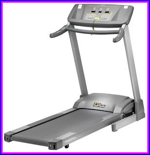
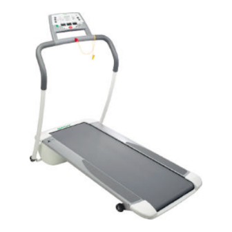
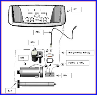
The main electrical components of the Tunturi
T10 and T20 are user interface (B02), power board (B44), motor (B18), lift
motor (B25) speed sensor (B23), and power cable (B29).
SERVICE MENUS
Engineering Mode
1. Enter the engineering mode after switching the treadmill POWER ON by pushing
first SELECT and then ENTER and hold buttons pressed simultaneously
2. The SPEED window shows the treadmill software version number, TIME window
shows the software design year and DISTANCE window shows the design date in “MM.DD” format
3. Press ENTER to show LDU version number (Display control software)
4. Press ENTER to show ISP version number
5. Press ENTER to enter KM/MILE switch mode,
1 for KM, 0 for MILE
Switch between the KM or MILE setting by pressing SPEED +/- or ELEVATION +/-
6. Press ENTER to show total distance
7. Press ENTER to show total usage hours
8. Press ENTER to return to the normal mode
Testing Mode
1. Enter the testing mode after switching the treadmill POWER ON by pushing
first SELECT and then SPEED DOWN and hold buttons pressed simultaneously
2. LED scanning mode for verifying display functionality
3. Press ENTER to scan DATA LINES to verify display functionality
4. Press ENTER to scan SACN LINES to verify display functionality
5. Press ENTER to scan LEDs to verify display functionality
6. After pressing ENTER the TIME window shows “test” and the keypad
functionality can be tested (the value displayed changes when a button is being
pressed)
7. Press ENTER to enter IO mode (TIME display shows lift motor potentiometer
value, SPEED reads speed from speed sensor and DISTANCE shows heart rate pulse)
Press START to test lower board relay (a click sound) and then press ELEVATION
UP for 2 seconds to increase the elevation to 8%. Press ELEVATION DOWN to decrease
the elevation to minimum percentage 0%
Press SPEED UP to increase speed value and ‘SPEED DOWN’ to decrease speed
value.
Press ENTER to repeat above test or SELECT and
SPEED DOWN buttons simultaneously to return to the normal mode.
Lift motor calibration
The lift motor calibration is done manually by following the following steps:
1. Drive the lift motor to 0% from user interface (inclination display must be
0%)
2. Switch off the treadmill and unplug the power cable
3. Remove motor cover
4. Fold up the running deck
5. Loosen two screws (A) attaching the lift motor nut (B) to the incline frame
6. Adjust the lift motor nut (B) so that there is 9 mm gap between the upper
end of the nut and the lift motor frame
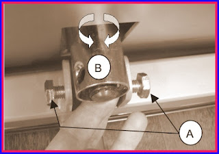
7. Tighten the screws (A) and verify correct
elevation by measuring
ERROR CODES
E1
The error will appear if the upper board cannot
receive pulses from the speed sensor for 10 seconds.
Possible reasons:
Speed sensor not properly assembled, the distance between the magnet and the
speed sensor should be less than 3mm.
Speed sensor cable disconnected
Meter cable has a poor connection at some point
Magnet missing from the front roller pulley
Front roller not rotating at all due to loose drive belt
Check the distance between the speed sensor and the flywheel and ensure that
the speed sensor is properly attached to the motor frame. Check also speed
sensor connections.
Error can be reset also by re-inserting the safety key.
E6
The error message appears when voltage is being
supplied to the lift motor but it doesn’t move.
Possible reasons:
Lift motor power cable disconnected
Lift motor electronically damaged preventing the movement
Error can be reset only by disconnecting the power cable.
E7
The values the lift motor potentiometer is
sending are not within the preset limits.
If the readout from the potentiometer is 1 the
software is not picking any signal from the potentiometer
Possible reasons:
Lift motor rotation sensor (potentiometer) cable disconnected
Lift motor rotation sensor has poor internal contact thus providing incorrect
values
The second connection cable between user interface and lower board disconnected
The potentiometer has lost its calibration and rotated to minimum
If the readout from the potentiometer has lost
its calibration setting and it differs from reference values adjust potentiometer
to obtain correct value.
If the potentiometer has lost its position it
can be lifted up after removing two attachment screws. Turn the potentiometer
shaft to obtain correct setting and place the potentiometer back to the lift
motor. To ensure that potentiometer maintains correct calibration setting a
small amount of glue should be added to shaft before inserting it back to its
counterpart.
Error can be reset also by re-inserting the
safety key.
TROUBLESHOOTING
Treadmill is making knocking noise
The best way to start finding the root cause of the problem is to listen to the
frequence of the noise. For example, the running belt seam overlaps a roller
twice per revolution, should this be the frequency of the noise, the belt needs
to be adjusted or replaced. If the noise has significantly higher frequency it
is likely to be caused by a damaged front or rear roller bearing.
Adjust the rear foot to make the treadmill deck even with the floor
Heart rate readings are inaccurate
The motor wires needs to be wrapped through a ferrite ring and twisted around
each other in order to prevent possible heart rate reading interference.
Home appliances, e.g. TV and mobile phone, and electric network can generate
interference. Try using equipment in different environment.
Circuit breaker (10A) trips repeatedly
Check that the treadmill is running mechanically free
Check belt lubrication
If the wall outlet voltage is lower than normal the required current is higher
and might cause the breaker to trip
Static electricity
Lubricate deck according to instructions in owner’s manual
Eliminate static electricity generators; user
should not use nylon clothing and/or should try another pair of different type
of training shoes
Ensure that the frame grounding wires are contacting steel by removing possible
paint between the wire connector and frame
Любая техника со временем выходит из строя и требует ремонта. Благодаря наличию на современных моделях дисплея по появившемуся коду ошибки беговой дорожки можно определить тип и причину неисправности.
Что делать при обнаружении кода ошибок у беговой дорожки
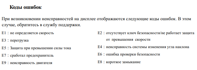
Для удобства обнаружения проблемы производители кодируют ошибки спортивного оборудования. Они обозначаются буквенно-числовой опознавательной комбинацией, начинающейся с буквы «Е» (сокращение от англ. «Error»).
Важно своевременно отреагировать на поломку и обратиться в наш сервисный центр. Мы производим восстановление беговых дорожек следующих брендов:
- Тorneo (Торнео);
- Ferrum (Феррум);
- Аerofit (Аэрофит);
- Kettler (Кетлер);
- Cardiopower (Кардиоповер);
- Yamaguchi (Ямагучи);
- Nautilus (Наутилус);
- Oxygen (Оксиген) и других.
Чаще всего при появлении кода ошибки на консоли беговой дорожки владелец оборудования впадает в ступор. Не все понимают, что они означают. В такой ситуации будет разумно вызвать нашего специалиста, который разбирается в значении кодов ошибок беговых дорожек.
Ошибка беговой дорожки Е1
Код Е01 на дисплее указывает на отсутствие контакта между платой управления, консолью и герконовым датчиком скорости. Такая ошибка часто появляется после небрежной перевозки тренажера. При этом происходят резкие рывки при старте и торможении.

Требуется проверка целостности соединяющего кабеля. Наш специалист открывает крышку моторного отсека, и определяет наличие магнита. Затем производит проверку соединений мультиметром. При необходимости ремонтирует или заменяет герконовый датчик.
Ошибка беговой дорожки Е2
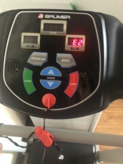
Ошибка Е02 означает неисправности в двигателе. При этом оборудование не может поддерживать скорость. Причиной могут быть:
- обрывы и замыкания;
- поломка контроллера управления;
- дефект обмотки.
Исправлять такую поломку самостоятельно не рекомендуется. Так как двигатель содержит взрывоопасные элементы. Обратитесь в наш сервисный центр за помощью. После диагностики мотора и приводного ремня мы определяем перечень требуемых работ и необходимых деталей.
Ошибка беговой дорожки Е3
Возникновение на консоли кода Е03 говорит об отсутствии сигнала с датчика скорости. Оборудование может отключаться после некоторого времени работы или не разгоняться до запрашиваемой скорости. При этом нарушается связь между двигателем и герконовым датчиком.
Неисправность встречается очень часто. Вы можете самостоятельно осмотреть деку беговой дорожки, она должна быть ровной и целой. После этого вызовите нашего мастера, он выполнит проверку мотора, датчика, платы и привода.
Ошибка беговой дорожки Е4
Этот код появляется в случае перегорания компонентов платы из-за скачков напряжения. Такая ситуация требует обращения в наш сервисный центр для выполнения замены вышедших из строя деталей.

Ошибка беговой дорожки Е5
Оборудование выдает ошибку Е05 при невозможности изменения угла наклона. Чаще всего это происходит из-за:
- попадания под полотно посторонних предметов;
- сбоев в работе датчиков подъемного механизма;
- превышения предельно допустимого веса пользователя.

Необходимо:
- проверить пространство под полотном;
- исключить использование тренажера пользователем с большим весом;
- обратиться за помощью к профессионалам нашего сервисного центра для тестирования работы датчиков.
Ошибка беговой дорожки Е6
Беговая дорожка показывает ошибку Е6 в случае перегрузки двигателя. Наши специалисты произведут проверку работы мотора на холостом ходу, целостность предохранителей.
При этом вес пользователя должен соответствовать предельно допустимым значениям.
Ошибка беговой дорожки Е7
Ошибка возникает при потере сигнала между кнопкой аварийного выключения и ключом безопасности. Не стоит устранять неисправность самостоятельно, так как, не обладая должным опытом и профессиональным оборудованием, можете усугубить ситуацию.
При данной поломке наш мастер проверит на месте ли ключ и целые ли провода между платой и кнопкой.
Ошибка беговой дорожки Е9
Ошибка Е09 заключается в отсутствии сигнала VR от двигателя на блок питания. Необходимо проверить провод или изменить наклон мотора. Возможно, потребуется замена блока управления. Данное действие под силу только опытным мастерам нашего сервисного центра.
Ошибка беговой дорожки Е11
Возникает ошибка из-за проблем со статическим напряжением. При этом электроника беговой дорожки может отключаться из-за сильных ударов статики. Как исправить проблему вам подскажет мастер нашего сервиса.
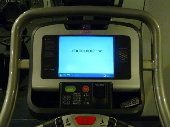
Ошибка беговой дорожки Е12
Данная ошибка возникает крайне редко и обычно свидетельствует о плохом контакте в розетке. Мастер проведет проверку, выяснит точную причину возникновения проблемы и поможет ее решить в короткие сроки.
Оформить заявку на устранение неисправностей можно по номеру телефона +7 (495) 223-12-48 или через форму обратной связи на сайте. Выезд мастера возможен в день обращения.
Наши специалисты имеют большой опыт в решении проблем, связанных с ошибками беговой дорожки. Мы гарантируем качество выполнения восстановительных работ любой сложности!