
Уважаемые клиенты данная таблица предоставлена только для общей информации. Консультации по поводу ошибок и прочих неисправностях мы не даем!
Уважаемые клиенты данная таблица предоставлена только для общей информации. Консультации по поводу ошибок и прочих неисправностях мы не даем!

3-10
3
РАБОТА ОРГАНОВ УПРАВЛЕНИЯ И ПРИБОРОВ
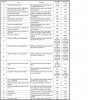
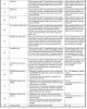
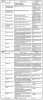
Указатель температуры
охлаждающей жидкости
1. Дисплей температуры охлаждающей жидкости
Дисплей температуры охлаждающей жид-
кости показывает температуру охлаждаю-
щей жидкости.
ECA10021
ПРЕДУПРЕЖДЕНИЕ
Не эксплуатируйте двигатель в случае
перегрева.
Устройство самодиагностики
1. Указатель кода ошибки
Данная модель оснащена устройством са-
модиагностики различных электрических
цепей.
Если какая-либо из этих цепей неисправ-
на, высвечивается сигнализатор неис-
правности двигателя, после чего много-
функциональный дисплей индицирует код
ошибки. Данная модель также оснащена
устройством самодиагностики системы
иммобилайзера.
Если какая-либо из цепей системы им-
мобилайзера неисправна, сигнализатор
системы иммобилайзера начинает мигать,
после чего дисплей одометра/счётчика
пути индицирует код ошибки.
ПРИМЕЧАНИЕ:
Если дисплей индицирует код 52, это мо-
жет быть вызвано взаимовлиянием транс-
пондеров. Если появляется данный код
ошибки, попробуйте следующее.
1. Воспользуйтесь ключом перерегист-
рации для запуска двигателя.
ПРИМЕЧАНИЕ:
Убедитесь, что вблизи замка зажигания
нет других ключей с функцией иммобилай-
зера и носите на связке ключей не более
одного ключа с функцией иммобилайзера!
Ключи системы иммобилайзера могут вы-
зывать взаимовлияние сигналов, что
предотвратит запуск двигателя.
2. Если двигатель запустится, остано-
вите его и попытайтесь запустить
при помощи стандартных ключей.
3. Если двигатель не запускается од-
ним или обеими стандартными клю-
чами, обратитесь к дилеру компании
YAMAHA для проведения процедуры
перерегистрации ключей, предоста-
вив мотоцикл, ключ перерегистра-
ции кода и оба стандартных ключа.
Если дисплей индицирует любые другие
коды ошибок, зафиксируйте их и обрати-
тесь в дилерскую организацию компании
YAMAHA для проверки мотоцикла.
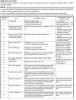
Для входа в режим диагностики и проверки существующих кодов ошибок в памяти системы необходимо проделать следующее:
1. Выключить зажигание, кнопку стоп-двигатель поставить в положение ВКЛ.
2. Отключить разъём бензонасоса.
3. Одновременно нажать кнопки SELECT + RESET на приборной панели и не отпускать.
4. Включить зажигание (кнопки всё ещё держим) и ждать ~8 секунд до появления на приборной панели надписи «dIAG».
5. Отпустить кнопки, кнопкой SELECT выбрать «dIAG» (для случая, если надпись на приборной панели появилась другая).
6. После того, как на экране отобразилась надпись dIAG нажать обе кнопки на приборной панели (SELECT + RESET) на ~2 секунды.
7. После того, как на приборной панели отобразится режим диагностики (d01) выключить кнопку стоп-двигателя.
8. Передвигаться по списку от d01 до d64 нужно используя кнопки SELECT (вверх по списку) или RESET (вниз по списку).
В диапазоне списка от d01 до d59 проводится процедура самодиагностики компонентов системы.
Включение некоторых компонентов осуществляется кнопкой стоп-двигатель.
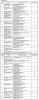
Список самодиагностики (напротив номера меню списка расшифровка показаний + номинальное значение):
D:01 = датчик положения дроссельной заслонки
полностью закрыты, показатели от 12 до 21
полностью открыты, показатели от 96 до 106
D:02 = атмосферное давление, в процентах;
D:03 = абсолютное атмосферное давление во впускном контуре;
D:05 = температура воздуха во впускном контуре;
D:06 = температура охлаждающей жидкости;
D:07 = показания датчика скорости;
D:08 = положение датчика падения
нормальное положение, показатель 0,4 — 1,4
перевернутое положение, показатель 3,7 — 4,4
D:09 = напряжение бортовой сети
D:13 = датчик положения дроссельных заслонок 2
полностью. закрыты, показатель от 9 до 23
полностью открыты, показатель от 94 до 108
D:14 = датчик положения ручки газа 1
полностью закрыта, показатель от 12 до 22
полностью открыта, показатель от 97 до 107
D:15 = датчик положения ручки газа 2
полностью закрыта, показатель от 10 до 24
полностью открыта, показатель от 95 до 109
D:20 = датчик положения боковой подножки;
D:21 = датчик положения КПП (нейтрали)
D:60 = EEPROM, лист ошибок системы (00 = ошибок нет, 01-04 = коды ошибок по цилиндрам, если в памяти более одной ошибки, то они показываются поочерёдно)
D:61 = лист ошибок модуля зажигания по датчикам (00 = нет ошибок в памяти, 11-70 = коды ошибок по компонентам, если в памяти более одной ошибки, то они показываются поочерёдно)
D:62 = количество ошибок в модуле памяти (00 = ошибок нет, XX — количество ошибок, стирание ошибок производится включением кнопки «стоп-двигатель»);
D:63 = подразряд кода ошибки (только для ошибки 24, если более одного значения в памяти, то значение отображается поочерёдно)
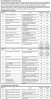
Список самодиагностики по агрегатам (компонентам системы зажигания/электрики):
D:30 = диагностика катушки зажигания 1 цилиндра;
D:31 = диагностика катушки зажигания 2 цилиндра;
D:32 = диагностика катушки зажигания 3 цилиндра;
D:33 = диагностика катушки зажигания 4 цилиндра;
D:34 = диагностика клапана впускной системы;
D:36 = диагностика первичного инжектора, форсунка 1
D:37 = диагностика первичного инжектора, форсунка 2
D:38 = диагностика первичного инжектора, форсунка 3
D:39 = диагностика первичного инжектора, форсунка 4
D:40 = диагностика вторичного инжектора, форсунка 1
D:41 = диагностика вторичного инжектора, форсунка 2
D:42 = диагностика вторичного инжектора, форсунка 3
D:43 = диагностика вторичного инжектора, форсунка 4
D:47 = диагностика датчика рулевого демпфера;
D:48 = диагностика датчика клапана впускной системы;
D:50 = диагностика реле бензонасоса;
D:51 = диагностика реле мотора вентилятора охлаждения;
D:52 = диагностика реле ламп головного света;
Расшифровка кодов ошибок системы (для строки D:60 и D:61):
№ ошибки — расшифровка
11 — ошибка датчика положения цилиндров;
12 — ошибка датчика положения коленвала;
13 — ошибка датчика давления во впуске (показания датчика вне пределов требуемого диапазона) — диагностируется строкой самодиагностики D:03;
14 — ошибка датчика давления во впуске (датчик отсоединён или неисправен) — диагностируется строкой самодиагностики D:03 ;
15 — ошибка датчика положения дроссельных заслонок — диагностируется строкой самодиагностики D:01 + D:13;
19 — ошибка на ECU от входящего сигнала (короткое замыкание или отключён датчик боковой подножки) — — диагностируется строкой самодиагностики D:20;
20 — ошибка показаний датчиков атмосферного и абсолютного давления во впуске, не допустимые значения, — диагностируется строкой самодиагностики D:03, D:02;
21 — ошибка показаний датчика температуры ОЖ, — диагностируется строкой самодиагностики D:06;
22 — ошибка датчика температуры во впуске, — диагностируется строкой самодиагностики D:05;
23 — ошибка показаний датчика атмосферного давления, — диагностируется строкой самодиагностики D:02;
24 — ошибка датчика кислорода (O2 сенсор, лямбда-зонд);
30 — ошибка датчика падения (сработавший или неисправный датчик), — диагностируется строкой самодиагностики D:08;
33 — неисправность катушки зажигания 1 цилиндра, — диагностируется строкой самодиагностики D:30;
34 — неисправность катушки зажигания 2 цилиндра, — диагностируется строкой самодиагностики D:31;
35 — неисправность катушки зажигания 3 цилиндра, — диагностируется строкой самодиагностики D:32;
36 — неисправность катушки зажигания 4 цилиндра, — диагностируется строкой самодиагностики D:33;
39 — неисправность контура первичного инжектора, — диагностируется строкой самодиагностики D:36,37,38,39;
40 — неисправность контура вторичного инжектора, — диагностируется строкой самодиагностики D:40,41,42,43;
41 — неисправность или короткое замыкание в проводке датчика падения, диагностируется строкой самодиагностики D:08;
42 — нет сигнала или неисправен датчик скорости, — диагностируется строкой самодиагностики D:07 (датчик скорости),D:21(датчик КПП (нейтрали));
43 — ошибка значения напряжения в контуре бензонасоса, — диагностируется строкой самодиагностики D:50;
44 — ошибка значений/данных системы диагностики/зажигания, — диагностируется строкой самодиагностики D:60
— 00 обозначает нормальное состояние показаний EEP-ROM;
— 01 обозначает нарушение в смесеобразовании 01 цилиндра
— 02 обозначает нарушение в смесеобразовании 02 цилиндра
— 03 обозначает нарушение в смесеобразовании 03 цилиндра
— 04 обозначает нарушение в смесеобразовании 04 цилиндра
46 — ошибка показатеей напряжения на модуле зажигания;
50 — ошибка работы памяти модуля зажигания;
59 — рассоединение или короткое замыкание в контуре датчика положения ручки газа, — диагностируется строкой самодиагностики D:14,15;
60 — ошибка системы YCC-T;
66 — неисправность концевика рулевого демпфера, — диагностируется строкой самодиагностики D:47;
70 — ошибка организации холостого хода (как симптом: двигатель начинает глохнуть на холостых после 20 минут работы);
Er-1 — нет входящего сигнала от модуля зажигания;
Er-2 — нет исходящего сигнала с модуля зажигания;
Er-3 — невозможно считать показания с модуля зажигания;
Er-4 — ошибка обмена данными с приборной панелью;
Процесс входа в режим диагностики:
1. Выключить зажигание. Выключить кнопку Start/Stop Engine (красная на правом пульте).
2. Нажать обе кнопки на приборке и ДЕРЖАТЬ ИХ.
3. Включить зажигание, держать кнопки после включения зажигания около 8 секунд.
4. Дождаться надписи DIAG.
5. Отпустить и нажать ОБЕ кнопки ВМЕСТЕ на приборке ещё раз на 2 сек., и отпустить.
6. Отобразится [d01]. Это первый диагностический показатель, показывает положение дросселей.
7. Кнопкой Select (верхняя) добраться до строки с номером [d60]. Эта ячейка показывает номер СУЩЕСТВУЮЩЕЙ на данный момент ошибки.
8. Посмотреть номер, стоящий напротив d61. Это номер ошибки В ПАМЯТИ «мозгов». Если ошибок несколько, они показываются попеременно.
Все ячейки диагностики выше 60 — и есть строки диагностики каждого из компонентов в отдельности. Подробнее — смотри НИЖЕ.
Для стирания ошибки из памяти системы заходишь на строку d62 и включаешь кнопку стоп-двигателя на правом пульте.
Подробно:
При входе в режим диагностике на дисплее отображается ячейка [d01].
Нажимая кнопку Select (верхняя) нужно перейти к показателю [d60] (самодиагностика в реальном времени) и [d61] (память ошибок) и посмотреть число рядом. Число рядом и есть номер ошибки, которую запомнил «мозг».
А все остальные числа от [d01] и до [d60] — это показатели различных датчиков (например [d01] -это положение ручки газа в процентах на данный момент, покрути и всё поймёшь).
Показатели (тестирование по датчикам включением стоп-двигателя):
d01 = положение ручки газа (крутить ручку газа)
d02 = атмосферное давление (абсолютное, в процентах)
d03 = разряжение во впуске (датчик в корпусе воздушного фильтра, в процентах)
d05 = температура воздуха во впуске (датчик в корпусе воздушного фильтра, номинал в процентах я так понимаю)
d06 = температура охлаждающей жидкости на данный момент
d07 = датчик скорости (показатель)
d08 = датчик падения (угла наклона)
d09 = напряжение на бензонасосе (тестируется включением стоп-двигателя)
d20 = боковая подножка (on/off) — тестирование работает только при выключенной нейтрали
d21 = датчик нейтрали (on/off)
d30 = катушка на 1 цилиндре (при включении кнопки стоп-двигателя производится тестирование катушки по 5 импульсов, сопутствует характерный звук, с одновр. морганием лампы Check Engine)
d31 = катушка на 2 цилиндре (при включении кнопки стоп-двигателя производится тестирование катушки по 5 импульсов, сопутствует характерный звук, с одновр. морганием лампы Check Engine)
d32 = катушка на 3 цилиндре (при включении кнопки стоп-двигателя производится тестирование катушки по 5 импульсов, сопутствует характерный звук, с одновр. морганием лампы Check Engine)
d33 = катушка на 4 цилиндре (при включении кнопки стоп-двигателя производится тестирование катушки по 5 импульсов, сопутствует характерный звук, с одновр. морганием лампы Check Engine)
d36 = форсунка 1 цилиндра (при включении кнопки стоп-двигателя производится тестирование форсунки по 5 импульсов, сопутствует характерный звук, с одновр. морганием лампы Check Engine)
d37 = форсунка 2 цилиндра (при включении кнопки стоп-двигателя производится тестирование форсунки по 5 импульсов, сопутствует характерный звук, с одновр. морганием лампы Check Engine)
d38 = форсунка 3 цилиндра (при включении кнопки стоп-двигателя производится тестирование форсунки по 5 импульсов, сопутствует характерный звук, с одновр. морганием лампы Check Engine)
d39 = форсунка 4 цилиндра (при включении кнопки стоп-двигателя производится тестирование форсунки по 5 импульсов, сопутствует характерный звук, с одновр. морганием лампы Check Engine)
d48 = AI клапан. (при включении кнопки стоп-двигателя производится тестирование клапана, 5 импульсов, сопутствует характерный звук, с одновр. морганием лампы Check Engine)
d50 = силовое реле инжектора и системы зажигания (тестируется так же кнопкой стоп-двигатель)
d51 = реле включения вентилятора охлаждения (тестируется так же кнопкой стоп-двигатель)
d52 = реле головного света (фар) (тестируется так же кнопкой стоп-двигатель)
d53 = тестирование мотора сервопривода EXUP (тестируется так же кнопкой стоп-двигатель, показывает значение в углах)
d56 = сервопривод вторичных заслонок (тестируется так же кнопкой стоп-двигатель, показывает значение в углах)
d60 = ошибка работы коммутатора (коды отображаются поочерёдно, перечень кодов ошибок коммутатора ниже)
d61 = записанный в память код ошибки
d62 = стирание записанных в память кодов ошибок
d70 = отображает код работающей программы (0-255)
Расшифровка показателя строки d60 (найденные самодиагностикой нарушения в работе датчиков):
11 = нет сигнала с датчика определения цилиндра
12 = нет сигнала с датчика положения коленвала
13 = ошибочный сигнал с датчика разряжения (в корпусе воздушного фильтра)
14 = неверный сигнал с датчика абсолютного давления
15 = ошибка датчика полоджеия дроссельных заслонок
16 = зафиксирована ошибка заклинивания датчика положения дроссельных заслонок
17 = зафиксирована ошибка датчика положения сервопривода EXUP
18 = ошибка заклинивания сервопривода EXUP
19 = короткое замыкание на блоке управления двигателем при нажатии кнопки запуска
20 = при включении кнопки стоп-двигателя обнаружена ошибка напряжения (большая разница показателей) на датчиках абсолютного давления и разряжения
21 = неисправность датчика температуры двигателя
22 = неисправность датчика температуры во впуске
23 = неисправность (короткое замыкание) датчика абсолютного давления
30 = зафиксировано срабатывание датчика падения (мотоцикл падал)
33 = короткое замыкание на управляющем проводе катушки зажигания 1 цилиндра
34 = короткое замыкание на управляющем проводе катушки зажигания 2 цилиндра
35 = короткое замыкание на управляющем проводе катушки зажигания 3 цилиндра
36 = короткое замыкание на управляющем проводе катушки зажигания 4 цилиндра
41 = неисправность или короткое замыкание на датчике падения
42 = отсутствие или ошибочный сигнал с датчика скорости
43 = ошибка измерения напряжения бортовой сети (короткое замыкание в проводке)
44 = неисправность блока управления двигателем
46 = нет напряжения на блоке инжектора
47 = ошибка сервопривода вторичных заслонок (обнаружено короткое замыкание или неисправность датчика)
48 = заклинивание или короткое замыкание в сервоприводе вторичных заслонок дросселя
50 = ошибка блока управления двигателем, невозможно прочитать ошибку
Er1 = нет сигнала от блока управления двигателем
Er2 = нет ответа от блока управления двигателем
Er3 = ошибка сигнала от блока управления двигателем
Er4 = неизвестный сигнал от блока управления двигателем
Если тахометр «зависает» на определенных оборотах:
Цитата(Александр С @ 13.4.2010, 9:58)
3000 — TPS
4000 — SPED SENSOR
7000 — EXUP
8000 — FUEL LEVEL INDIKATOR
9000 — EMARGENCY STOP SWITCH
Полезная информация!
У мотоциклов Yamaha встроенная самодиагностика неисправностей.
При включении зажигания на прибороной доске загорается индикатор иммобилайзера красного цвета.
По миганию его можно определить неисправность.
С начало он моргает медленно пять раз- это равно первой цифре кода. Потом быстро- это вторая цифра кода.
Некоторые расшифровки кодов:
5-1 — не видит чипа в ключе. Скорее всего проблема в чипе.
5-2 — чип в ключе не от этого мотоцикла. Скорее всего вы взяли чип-ключ от другого мотоцикла.
5-3 — нет связи между блоком управления двигателем и блоком иммобилайзера. Проверте разъемы проводки мотоцикла.
5-4 — нет синхронизации между блоком управления двигателем и блоком иммобилайзера. Перепутанные блоки- моторного и иммо.
Источник: http://www.yamaha-r1.ru/forum/index.php?showtopic=5999&hl=%E4%E8%E0%E3%ED%EE%F1%F2%E8%EA%E0
![]()
РАБОТА ОРГАНОВ УПРАВЛЕНИЯ И ПРИБОРОВ
|
Температура охлаждающей |
Дисплей |
Состояние |
Решение проблем |
|
|
жидкости |
||||
|
3 |
||||
|
Высвечивается |
Нормальная ситуация. |
|||
|
Ниже 39 °С |
сообщение «LO» |
|||
|
Продолжайте движение. |
||||
|
(НИЗКАЯ ТЕМПЕРАТУРА). |
||||
|
40–116 °С |
Высвечивается значение |
Нормальная ситуация. |
|
|
температуры. |
Продолжайте движение. |
||
|
Остановитесь и дайте |
|||
|
двигателю поработать на |
|||
|
Дисплей указателя температу- |
холостом ходу до понижения |
||
|
117–134 °С |
ры мигает. Загорается сигналь- |
температуры охлаждающей |
|
|
ная лампа. |
жидкости. Если температура |
||
|
не понижается, остановите |
|||
|
двигатель. (См. стр. 6-43) |
|||
|
Сообщение «HI» (ВЫСОКАЯ ТЕМ- |
Остановите двигатель |
||
|
Выше 135 °С |
ПЕРАТУРА) мигает. Загорается |
и дайте ему остыть. |
|
|
сигнальная лампа. |
(См. стр. 6-43) |
3-6

РАБОТА ОРГАНОВ УПРАВЛЕНИЯ И ПРИБОРОВ
EAU11534
Сигнальная лампочка неисправности в двигателе « »
»
3Эта сигнальная лампочка горит непрерывным светом или мигает при неполадках в работе электрической схемы двигателя. В случае неполадок обратитесь к официальному представителю компании Yamaha для проверки системы самодиагностики (смотрите пояснение работы устройства самодиагностики на странице 3-10).
Электрическую схему сигнальной лампочки можно проверить, повернув ключ в положение ON [Включено]. Сигнальная лампочка должна загореться на несколько секунд, а затем снова погаснуть. Если при повороте ключа в положение ON сигнальная лампа не загорается или продолжает гореть и не гаснет, обратитесь к официальному представителю компании Yamaha для проверки электрической цепи.
EAU11545
Сигнальная лампочка антиблокировочной системы (АБС) « » (для моделей, оснащенных АБС)
Если данная сигнальная лампа загорается или мигает во время поездки, антиблокировочная система может сработать некорректно. При обнаружении подобной неполадки обратитесь к официальному представителю компании Yamaha для проверки мотоцикла. (См. стр. 3-14.)
EWA10081
 ПРЕДОСТЕРЕЖЕНИЕ
Если сигнальная лампа антиблокировочной системы загорается или мигает во время поездки, тормозная система возвращается к нормальному режиму работы. Таким образом, будьте осторожны и постарайтесь не блокировать колёса при экстренном торможении. Если сигнальная лампа загорается или мигает во время поездки, как можно скорее обратитесь к официальному представителю компании Yamaha для проверки тормозной системы.
Электрическую схему сигнальной лампочки можно проверить, повернув ключ в положение ON. Сигнальная лампочка должна загореться на несколько секунд, а затем снова погаснуть. Если при повороте ключа в положение ON сигнальная лампа не загорается или продолжает гореть и не гаснет, обратитесь к официальному представителю компании Yamaha для проверки электрической цепи.
EAU38624
Индикатор системы блокировки
Электрическую схему индикатора можно проверить, повернув ключ в положение ON [Включено]. Индикатор должна загореться на несколько секунд, а затем снова погаснуть. Если при повороте ключа в положение ON индикатор не загорается или продолжает гореть и не гаснет, обратитесь к официальному представителю компании Yamaha для проверки электрической цепи.
По прошествии 30 секунд после поворота ключа в положение OFF [Выключено] индикатор начнет мигать, информируя об активации системы блокировки. По истечении 24 часов данный индикатор перестанет мигать, однако система блокировки останется включенной.
Данная модель мотоцикла также оборудована устройством самодиагностики для системы блокировки. (Разъяснения по устройству самодиагностики можно посмотреть на стр. 3-10.)
3-7
РАБОТА ОРГАНОВ УПРАВЛЕНИЯ И ПРИБОРОВ
EAU46764
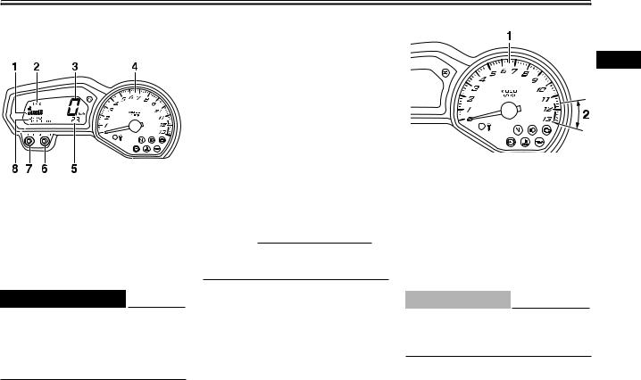
Многофункциональная панель приборов
1.Указатель уровня горючего
2.Указатель температуры охлаждающей жидкости
3.Спидометр
4.Тахометр
5.Одометр / Счетчик пройденного пути / Счетчик пройденного пути на резервном запасе топлива
6.Кнопка SELECT [Выбор]
7.Кнопка RESET [Сброс]
8.Часы
EWA12422
 ПРЕДОСТЕРЕЖЕНИЕ
Перед осуществлением каких-либо изменений настроек многофункциональной панели приборов необходимо остановить мотоцикл. Изменение настроек во время езды может отвлечь водителя и увеличит риск аварии.
В составе многофункционального дисплея имеются следующие приборы:
●спидометр
●тахометр
●одометр
●два счетчика пройденного пути (показывают расстояние, пройденное с момента последнего обнуления показаний)
●счетчик пройденного пути на резервном запасе топлива (показывает расстояние, пройденное с того момента, когда начал мигать левый сегмент указателя уровня топлива)
●часы
●указатель уровня топлива
●указатель температуры охлаждающей жидкости
●устройство самодиагностики.
ПРИМЕЧАНИЕ
Поверните ключ в положение ON [Вкл.] до использования кнопок SELECT [Выбор] и RESET [Сброс].
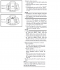
Тахометр
3
1.Тахометр
2.Красная зона тахометра
Тахометр позволяет водителю следить за частотой вращения двигателя и сохранять его в идеальном диапазоне мощности.
При повороте ключа в положение ON [Вкл.] последовательно загорятся и погаснут все сегменты многофункционального дисплея в порядке тестирования электрических цепей.
ECA10031
ПРЕДУПРЕЖДЕНИЕ
Нельзя допускать работы двигателя в красной зоне тахометра.
Красная зона: 11500 об/мин и выше
3-8
РАБОТА ОРГАНОВ УПРАВЛЕНИЯ И ПРИБОРОВ
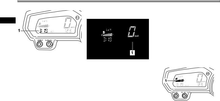
Часы
3
1.Часы
Установите ключ зажигания в положение ON [Вкл.], чтобы перевести панель в режим часов. Кроме того, чтобы отобразить часы на 10 секунд, нажмите кнопку SELECT [Выбор], когда ключ зажигания находится в следующих положениях: OFF [Выключено], LOCK [Блокировка] или  [Стоянка].
Как установить часы
1.Поверните ключ зажигания в положение ON [Вкл.].
2.Одновременно нажмите на кнопку SELECT и RESET и удерживайте их не мене 2 секунд.
3.Когда разряд часов начнет мигать, нажмите кнопку RESET для установки часов.
4.Нажмите кнопку SELECT для перехода к разряду минут, который начнет мигать.
5.Нажмите кнопку RESET, чтобы произвести настройку минут.
6.Нажмите и отпустите кнопку SELECT для
запуска часов.
Режимы одометра и счетчика пути
1.Одометр / Счетчик пройденного пути / Счетчик пройденного пути на резервном запасе топлива
тром в следующем порядке: F-TRIP [Счетчик пройденного пути на резервном остатке топлива] → TRIP A [Счетчик пройденного пути A] → TRIP B [Cчетчик пройденного пути B] – ODO [Счетчик пробега] → F-TRIP.
Для сброса счетчика пройденного пути в нулевое значение необходимо выбрать его, нажав кнопку SELECT, а затем зажать RESET на 1 секунду. Если вы не сбрасываете показания счетчика пройденного пути на резервном запасе топлива вручную, то он сбросит показания автоматически, а дисплей перейдет в предыдущий режим после дозаправки и прохождения 5 км пути.
Указатель уровня топлива
Нажатие кнопки SELECT приводит к переключению
дисплея между режимом одометра ODO и режимами счетчиков пройденного пути TRIP A и TRIP B в следующей последовательности: TRIP A [Счетчик пройденного пути A] →TRIP B
[Cчетчик пройденного пути B] → ODO [Счетчик пробега] → TRIP A [Счетчик пройденного пути A]. Когда в топливном баке остается приблизительно 3,4 л топлива, левый сегмент указателя уровня топлива начинает мигать, а режим одометра автоматически переключится в режим счетчика пройден-
ного пути на резервном остатке топлива F-TRIP и начинает отсчет пройденного пути с этого момента. В этом случае нажатие кнопки SELECT приводит к переключению дисплея между различными режимами счетчиков пройденного пути и одоме-
1. Указатель уровня топлива
3-9
РАБОТА ОРГАНОВ УПРАВЛЕНИЯ И ПРИБОРОВ
Указатель уровня горючего отображает количество горючего в топливном баке. Сегменты указателя исчезают с дисплея по направлению к «E» (пустой) по мере уменьшения уровня горючего в баке. Когда замигает последний сегмент указателя уровня горючего, вам необходимо как можно быстрее дозаправиться.
ПРИМЕЧАНИЕ
Указатель уровня горючего данной модели оборудован системой самодиагностики. При нарушении электрической схемы повторяется следующий цикл до устранения неисправности: все сегменты указателя и символ « » мигают 8 раз, затем выключаются приблизительно на 3 секунды. При возникновении данной неполадки, обратитесь к официальному представителю компании Yamaha для проверки целостности электрических цепей.
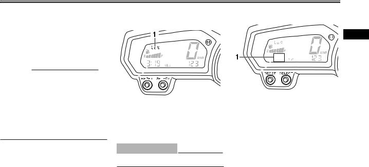
Режим указателя температуры охлаждающей жидкости
1.Дисплей указателя температуры охлаждающей жидкости
Дисплей указателя температуры охлаждающей жидкости отображает температуру охлаждающей жидкости.
ECA10021
ПРЕДУПРЕЖДЕНИЕ
Двигатель не должен работать, если он перегрелся.
Устройство самодиагностики
3
1. Дисплей кода ошибки
Данная модель мотоцикла оснащается устройством самодиагностики для проверки различных электрических схем.
Если какая-либо электросхема выйдет из строя, на панели приборов загорится сигнальная лампочка неполадок в двигателе, а на дисплее отобразится код ошибки.
Устройство самодиагностики также определяет неполадки в электрической цепи системы блокировки.
Если какая-либо из цепей системы блокировки неисправна, то замигает индикатор системы блокировки, а затем на дисплее отобразится код ошибки.
3-10
РАБОТА ОРГАНОВ УПРАВЛЕНИЯ И ПРИБОРОВ
ПРИМЕЧАНИЕ Если на дисплее отобразился код ошибки 52, то
это могло произойти из-за интерференции прие-
3мопередатчика. Если возник такой код ошибки, необходимо выполнить следующие действия.
1.Использовать ключ для перерегистрации кода, чтобы запустить двигатель.
ПРИМЕЧАНИЕ Необходимо обеспечить, чтобы около замка зажи-
гания не было других ключей блокировки, и нельзя держать более одного ключа блокировки на одном кольце для ключей! Ключи системы блокировки могут послужить причиной интерференции сигналов, что может помешать запуску двигателя.
2.Если двигатель запустился, то надо его выключить и попробовать запустить с помощью стандартных ключей.
3.Если один или оба стандартных ключа не запускают двигатель, то необходимо доставить мотоцикл, ключ для перерегистрации кода и оба стандартных ключа к официальному представителю компании Yamaha для перерегистрации стандартных ключей.
Если на дисплее появился код ошибки, запишите ее номер и обратитесь к официальному представителю компании Yamaha для проверки мотоцикла.
ECA11590
ПРЕДУПРЕЖДЕНИЕ
Если на дисплее появился код ошибки, доставьте ваш мотоцикл в сервисную службу как можно скорее во избежание возможных повреждений двигателя.
EAU12331
Противоугонная сигнализация (дополнительно)
Данная модель мотоцикла может быть оборудована дополнительной противоугонной сигнализацией по выбору представителем компании Yamaha. Для получения более подробной информации обращайтесь к официальному представителю компании Yamaha.
3-11
РАБОТА ОРГАНОВ УПРАВЛЕНИЯ И ПРИБОРОВ
EAU12348
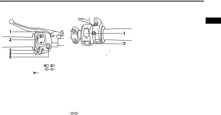
Рулевые переключатели
Левые
1.Кнопка помигивания дальним светом « »
»
|
2. |
Переключатель дальний/ближний свет « |
/ |
» |
|
3 |
Переключатель указателя поворотов « |
/ |
» |
4.Кнопка звукового сигнала « »
»
5.Выключатель аварийной сигнализации « »
»
Правые
1.Выключатель двигателя « /
/ »
»
2.Кнопка запуска двигателя « »
»
E AU12350
Кнопка помигивания дальним светом « »
»
Нажимайте кнопку для помигивания дальним светом.
EAU12400
Переключатель дальний/ближний свет «
 /
/ »
»
Установите переключатель в положение « » для включения дальнего света и в положение «
 » для включения ближнего света.
Переключатель указателя поворотов «
»
Для подачи сигнала поворота направо переведите этот переключатель в положение « ». Для подачи сигнала поворота налево переведите этот переключатель в положение «
 ».
».
Будучи отпущен, переключатель возвращается в
центральное положение. Для прекращения подачи сигналов поворота нажмите на переключатель после его возврата в центральное положение.
3
EAU12500
Кнопка звукового сигнала « »
»
Нажимайте кнопку для подачи звукового сигнала.
EAU12660
Выключатель двигателя « /
/ »
»
Перед запуском двигателя установите этот выключатель в положение « ». Установите этот выключатель в положение «
 » для остановки двигателя в экстренных случаях, таких как опрокидывание мотоцикла или заедание троса привода дроссельной заслонки.
EAU12711
Кнопка запуска двигателя « »
»
Нажимайте кнопку для запуска двигателя при помощи стартера. Прежде чем запускать двигатель, прочтите инструкции по запуску на стр. 5-1.
EAU44710
Когда ключ зажигания находится в положении ON [Вкл.] и нажимается кнопка запуска двигателя, загораются сигнальные лампочки неполадок в двигателе и антиблокировочной системы (для моделей, оснащенных АБС). Однако в данном случае это не является признаком неполадок или неисправностей.
3-12
РАБОТА ОРГАНОВ УПРАВЛЕНИЯ И ПРИБОРОВ
EAU12733
Выключатель аварийной сигнализации « »
»
Когда ключ зажигания находится в положении ON
3[Вкл.] или  [Стоянка], с помощью данного выключателя можно активировать аварийную сигнализацию (одновременное мигание всех ламп сигналов поворота).
Аварийная сигнализац ия используется в случае аварии или для предупреждения других водителей, когда ваше транспортное средство остановлено в месте, где существует опасность дорожнотранспортного происшествия.
ECA10061
ПРЕДУПРЕЖДЕНИЕ
Нельзя использовать аварийную сигнализацию в течение продолжительного времени при выключенном двигателе, в противном случае может разрядиться аккумуляторная батарея.
|
EAU12820 |
EAU12870 |
|
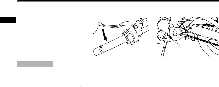
Рычаг сцепления |
Педаль переключения скоростей |
|
1. Рычаг сцепления |
1. Педаль переключения скоростей |
|
Рычаг сцепления расположен на левой рукоятке |
|
|
руля. Чтобы отключить сцепление, прижмите ры- |
Педаль переключения скоростей расположена с |
|
чаг к рукоятке. Чтобы снова включить его, отпу- |
левой стороны мотоцикла и используется в соче- |
|
стите рычаг. Рычаг нужно нажимать быстро, а от- |
тании с рычагом сцепления для переключения пе- |
|
пускать медленно для смягчения работы механиз- |
редач 6-скоростной коробки переключения пере- |
|
ма сцепления. |
дач с постоянным зацеплением, которой оборудо- |
|
Рычаг сцепления оборудован переключателем |
ван данный мотоцикл. |
|
сцепления, который является составной частью |
|
|
цепи системы отключения зажигания (Смотрите |
|
|
описание системы отключения зажигания на стра- |
|
|
нице 3-23.) |
3-13
РАБОТА ОРГАНОВ УПРАВЛЕНИЯ И ПРИБОРОВ
EAU26823
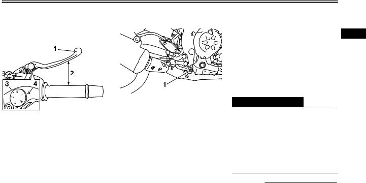
Рычаг переднего тормоза
Рычаг переднего тормоза расположен на руле справа. Для использования переднего тормоза прижмите рычаг к рукоятке.
1.Рычаг тормоза
2.Расстояние между рычагом тормоза и рукояткой
3.Лимб регулирования положения рычага тормоза
4.Метка 
EAU12941
Педаль тормоза
1.Педаль тормоза
Педаль тормоза расположена с правой стороны мотоцикла. Для использования заднего тормоза нажмите на педаль.
Рычаг переднего тормоза оборудован диском для регулировки положения. Для регулировки расстояния между рычагом переднего тормоза и рукояткой руля необходимо поворачивать регулировочный диск, удерживая рычаг переднего тормоза отжатым от ручки руля. Убедитесь, что соответствующая отметка на регулировочном диске выровнена с отметкой « » на рычаге тормоза.
3-14
EAU47521
Антиблокировочная система (для моделей с АБС)
АБС (антиблокировочная тормозная система) компа- 3 нии Yamaha состоит из двух электронных управляющих систем, которые функционируют независимо друг от друга для переднего и заднего тормозов. Антиблокировочная система работает под управлением электронного управляющего блока (Electronic Control Unit — ECU), который возвращается к ручному торможению, если возникает неисправность.
EWA10090
 ПРЕДОСТЕРЕЖЕНИЕ
●АБС наилучшим образом работает на длинной тормозной дистанции.
●На некоторых (неровных или гравийных) дорогах тормозная дистанция с использованием АБС может быть длиннее, чем без использования АБС. Таким образом, необходимо всегда сохранять достаточную дистанцию до впереди идущего транспортного средства, чтобы успеть затормозить при текущей скорости.
ПРИМЕЧАНИЕ
●АБС осуществляет самодиагностику в течение нескольких секунд каждый раз, когда транспортное средство заводится после переключения замка зажигания в положение ON [Вкл.]. В ходе этого теста из-под сидения можно услышать «щелкающий» звук и, если рычаг или пе-
РАБОТА ОРГАНОВ УПРАВЛЕНИЯ И ПРИБОРОВ
даль тормоза хотя бы немного выжаты, то на этом рычаге можно почувствовать вибрацию, однако это не является признаком неисправ-
3ности.
|
● |
При активации АБС тормоза работают обыч- |
||
|
ным образом. На рычаге или педали тормоза |
|||
|
можно чувствовать пульсации, однако это не |
|||
|
является признаком неисправности. |
|||
|
● |
Установленная АБС имеет режим тестирова- |
||
|
ния, который позволяет пользователю ощу- |
|||
|
тить пульсации на рычагах тормозов при рабо- |
1 |
Ступица заднего колеса |
|
|
те АБС. Однако для проведения этого теста не- |
2 |
Ступица переднего колеса |
|
|
обходимы специальные инструменты, поэто- |
|||
|
му, пожалуйста, проконсультируйтесь с вашим |
|||
|
дилером компании Yamaha. |
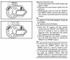
ECA16120
ПРЕДУПРЕЖДЕНИЕ
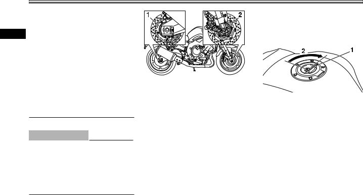
Нельзя допускать наличия вблизи ступиц переднего и заднего колес каких-либо магнитов (включая инструменты с магнитным захватом, магнитные отвертки и т.д.), в противном случае могут повредиться магнитные роторы, которыми оборудованы ступицы колес, что приведет к неправильной работе АБС.
EAU13074
Крышка топливного бака
1.Крышка замка топливного бака
2.Открыть
Как открыть топливный бак
Откройте крышку замка топливного бака, вставьте ключ в замок, а затем поверните его на 1/4 оборота по часовой стрелке. Вы разблокируете замок и сможете открыть колпачок топливного бака.
Как закрыть топливный бак
1.Вставьте ключ в замок и установите крышку топливного бака на место.
2.Поверните ключ в замке против часовой стрелки в начальное положение, извлеките его и закройте крышку замка.
3-15
Соседние файлы в предмете [НЕСОРТИРОВАННОЕ]
- #
- #
- #
- #
- #
- #
- #
- #
- #
- #
- #
-
#26
товарищи!кто то поможет ?
-
#27
33 и 34 это ошибки катушек зажигания 35 ошибки не существует посмтри катушки, либо короткое замыкание, либо предохранители
-
#28
makarkharp написал(а):
нитра мтх2008год ошибки 33,34,35,двигло не запускается,скинул клемы,горит так же тревожная лампулька(засел в сугробе,газовал но без фанатизма) датчик температурвы не горит,значит не перегрев…
что за хрень?
Могу сказать завтра что означают сии ошибки, но господа, всегда помните что ошибка не всегда напрямую указывает на неисправность, без хорошего понимания алгоритма работы инжектора и мотора в целом, а так же назначения и устройства всех датчиков и систем и их влияния на работу двигателя сложно чинить современные инжекторные моторы. И могу привезти кучу примеров когда ошибка в мозгах упорно указывала на одно ,а на деле было совсем другое.
-
#29
Держите только не все  MP как и на всех снежниках срабатывают коды 84 система торс ;13 и 14 датчики давления воздуха на впуске; 30 датчик масла ;42 ошибка датчика скорости либо что чаще бывает его разрушение валом привода гусеницы,81 короткое замыкание в цепи подогрева ручек.
-
#30
Кстати про ошибки если у вас сломан датчик скорости и горит сигнальный код 42 то скорее всего загорится ещё и код 84 так как инжектор не пойме почему обороты двигателя к примеру 5000 а скорость 0
-
#31
33,34,35 только на Nitro так как у неё 3 катушки зажигания соответственно у RX 1 за коды отвечают 30,31,32,33 так что у MP коды катуше 33,34
-
#32
ДА, правильно 33, 34,35 ошибки указывают на катушки зажигания, но все разом выйти из строя они не должны, наверное причина в чем то другом. А так для справки сопротивление первичной обмотки катушки 1,19-1,61 Ома при 20 градусах цельсия, вторичной обмотки 8,5-11,5 кОм при 20 градусах. Проверяйте.
-
#33
yamahavmax1200 написал(а):
33,34,35 только на Nitro так как у неё 3 катушки зажигания соответственно у RX 1 за коды отвечают 30,31,32,33 так что у MP коды катуше 33,34
30 датчик масла ты же говоришь?
-
#34
30 — датчик давления масла, точно
-
#35
NEOS написал(а):
30 — датчик давления масла, точно
а есть помимо кодов еще пишет ER—-1. или Er—2 и так до 4х так вот мучиимся с Er—1и горит температура и чек что делать?
-
#36
А у меня 84 периодически загорается и работает только на холостых,газу даешь — отсечка срабатывает.Через пол минуты проходит.За день три раза было такое.Что за хрень?
-
#37
поль написал(а):
Ваша хрень очень подробно расписана в инструкции по эксплуатации — которую Вы даже не соизволили посмотреть. 
Эта «хрень» называется расписьдяйство.
-
#39
Действительно смешно,в моей инструкции про это ничего не сказано,а у «ГДЕ» даже расписьдяйством обозначено.
Поделитесь уж эксклюзивом с народом,что же это за неполадки такие.
-
#40
поль написал(а):
Действительно смешно,в моей инструкции про это ничего не сказано,…
Поделитесь уж эксклюзивом с народом,что же это за неполадки такие.
Действительно смешно.
Видно тебе выдали какую-то эксклюзивную инструкцию — во всех остальных это указывается и с картинками и с описанием проверки и устранения.
Торкс у тебя подглючивает — какой уж тут эксклюзив.
-
#41
Андреич ,не тыркс а T.O.R.S.
где снех,где снех,тут я или мало?еще навалим
-
#42
снех написал(а):
Андреич
,не тыркс а T.O.R.S.
Пардон — поленился переключаться с кирилицы на латыницу и обратно.
Надеюсь понятно о чём речь, даже в русской транскрипции.
снех написал(а):
 О — нашёлся
Валяй.
Чем больше тем меньше чайников под ногами путается
-
#43
Андреич,я всегда рядом и подправлю,пока у тя такой аватар
ну я посыпал…..
-
#44
Андреевич написал(а):
Петрович, не криви душой. Я выполняю что обещаю.
Почту смотри свою.
Удачи.
Я так подрозумеваю в почте коды с расшифровками,а выложить их для всех слабо???
-
#45
Андрейка 1 написал(а):
Я так подрозумеваю в почте коды с расшифровками,а выложить их для всех слабо???
На «слабо» не реагирую где-то со старшей группы детского сада
А коды уже давно выложены на форуме
-
#46
Это хорошо,что не поддаешся на правокацию,А где лежат ссылку кинь на страницу ,быстрей будет Плииз.
-
#47
-
1.008,6 KB
Просмотры: 405 -
696 KB
Просмотры: 382
-
#48
Коды и вход в диагностику из сервис-мануалов Ямаха
Внимание парни! неправильная или неграмотная работа с кодами диагностики ( в том числе прямые попытки воздействовать на механизмы с целью изменить их параметры) могут привести к серьезной аварии даигателя снегохода, что может привести к травме и (или) смерти как водителя так и находящихся рядом людей. Например, включение механизма «проверка искрового разряда» в режиме дисплея «диагностика» может вызвать воспламенение смеси в цилиндре ДВС, что приведет к проворачиванию коленвала и возможному увечью или смерти в результате внезапного движения снегохода)
Все действия Вы выполняете на свой стах и риск, полностью осознавая возможные последствия.
Внимание! Коды диагностики, высвечивающиеся на дисплее — это не то же самое что коды высвечивающиеся при нахождении дисплея в режиме «диагностика».
Так как в фирменном сервис мануале все устройства снегохода названы на янглийском языке, в таблице диагностики все расшифровки кодов приведены на английском языке. Это чтобы не было путаницы, когда код из-за сокращения написания оригинального языка переведен на русский как «ошибка положения дросселя» а в сервис — мануале устройство названо «accelerator lever assy»  :)")
YAMAHA NITRO
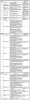
Коды высвечивающиеся на дисплее
Перевод дисплея в режим «диагностика»
Диагностические параметры проверяемые в режиме дисплея «диагностика»
-
183,7 KB
Просмотры: 10.309 -
336,2 KB
Просмотры: 10.129 -
191,9 KB
Просмотры: 11.384 -
226,1 KB
Просмотры: 10.075

-
#49
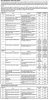
YAMAHA PZ50 (модельнsй ряд 8GC) (2х-цилиндровые ДВС YAMAHA Genesis)
Коды высвечивающиеся на дисплее
Вход в режим дисплея «диагностика»
Коды совмещения (таблица отношения кодов диагностики высвечиваемым на дисплее к диагностическим параметрам проверяемым в режиме «диагностика» в случае появления этих кодов)
Диагностические параметры проверяемые в режиме дисплея «диагностика»
-
145 KB
Просмотры: 11.155 -
336,2 KB
Просмотры: 8.568 -
184,4 KB
Просмотры: 11.602 -
209,1 KB
Просмотры: 8.962
-
#50
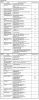
YAMAHA VENTURE GT (Модельный ряд 8HF) (3х-цилиндровые ДВС Yamaha Genesis)
Коды высвечивающиеся на дисплее
Вход в режим дисплея «диагностика»
Коды совмещения (таблица отношения кодов диагностики высвечиваемым на дисплее к диагностическим параметрам проверяемым в режиме «диагностика» в случае появления этих кодов)
Диагностические параметры проверяемые в режиме дисплея «диагностика»
-
129,1 KB
Просмотры: 10.896 -
48,6 KB
Просмотры: 8.975 -
144,2 KB
Просмотры: 9.671 -
159 KB
Просмотры: 8.355
- Manuals
- Brands
- Yamaha Manuals
- Motorcycle
- FZ8-NA
- Service manual
-
Contents
-
Table of Contents
-
Troubleshooting
-
Bookmarks
Related Manuals for Yamaha FZ8NA
Summary of Contents for Yamaha FZ8NA
-
Page 1
2011 SERVICE MANUAL FZ8NA FZ8SA 1BD-28197-E0… -
Page 2
EAS20040 FZ8NA FZ8SA SERVICE MANUAL ©2010 by Yamaha Motor Co., Ltd. First edition, May 2010 All rights reserved. Any reproduction or unauthorized use without the written permission of Yamaha Motor Co., Ltd. is expressly prohibited. -
Page 3
EAS20071 IMPORTANT This manual was produced by the Yamaha Motor Company, Ltd. primarily for use by Yamaha deal- ers and their qualified mechanics. It is not possible to include all the knowledge of a mechanic in one manual. Therefore, anyone who uses this book to perform maintenance and repairs on Yamaha vehicles should have a basic understanding of mechanics and the techniques to repair these types of vehicles. -
Page 4: How To Use This Manual
EAS20091 HOW TO USE THIS MANUAL This manual is intended as a handy, easy-to-read reference book for the mechanic. Comprehensive explanations of all installation, removal, disassembly, assembly, repair and check procedures are laid out with the individual steps in sequential order. •…
-
Page 5
EAS20101 SYMBOLS The following symbols are used in this manual for easier understanding. The following symbols are not relevant to every vehicle. SYMBOL DEFINITION SYMBOL DEFINITION Serviceable with engine Gear oil mounted Filling fluid Molybdenum disulfide oil Lubricant Brake fluid Special tool Wheel bearing grease Tightening torque… -
Page 7: Table Of Contents
EAS20110 TABLE OF CONTENTS GENERAL INFORMATION SPECIFICATIONS PERIODIC CHECKS AND ADJUSTMENTS CHASSIS ENGINE COOLING SYSTEM FUEL SYSTEM ELECTRICAL SYSTEM TROUBLESHOOTING…
-
Page 9: Table Of Contents
GENERAL INFORMATION IDENTIFICATION ………………1-1 VEHICLE IDENTIFICATION NUMBER………..1-1 MODEL LABEL ………………1-1 FEATURES ………………..1-2 OUTLINE OF THE FI SYSTEM …………..1-2 FI SYSTEM …………………1-4 INSTRUMENT FUNCTIONS …………..1-5 OUTLINE OF THE ABS …………….1-8 ABS COMPONENT FUNCTIONS …………1-14 ABS OPERATION ……………..1-19 ABS SELF-DIAGNOSIS FUNCTION …………1-22 ABS WARNING LIGHT AND OPERATION………..1-25 IMPORTANT INFORMATION …………..1-26 PREPARATION FOR REMOVAL AND DISASSEMBLY……1-26…
-
Page 10: Identification
IDENTIFICATION EAS20130 IDENTIFICATION EAS20140 VEHICLE IDENTIFICATION NUMBER The vehicle identification number “1” is stamped into the right side of the steering head pipe. EAS20150 MODEL LABEL The model label “1” is affixed to the frame. This information will be needed to order spare parts.
-
Page 11: Outline Of The Fi System
FEATURES EAS20170 FEATURES EAS39P1101 OUTLINE OF THE FI SYSTEM The main function of a fuel supply system is to provide fuel to the combustion chamber at the opti- mum air-fuel ratio in accordance with the engine operating conditions and the atmospheric tempera- ture.
-
Page 12
10.Battery 11.Atmospheric pressure sensor 12.Relay unit (fuel pump relay) 13.Lean angle sensor 14.Catalytic converter 15.O sensor 16.Fuel hose 17.Fuel injector 18.Crankshaft position sensor 19.Coolant temperature sensor 20.Spark plug 21.Ignition coil 22.Cylinder identification sensor 23.Air cut-off valve A. FZ8NA B. FZ8SA… -
Page 13: Fi System
FEATURES EAS39P1102 FI SYSTEM The fuel pump delivers fuel to the fuel injector via the fuel filter. The pressure regulator maintains the fuel pressure that is applied to the fuel injector at only 324 kPa (3.24 kgf/cm², 46.1 psi). Accordingly, when the energizing signal from the ECU energizes the fuel injector, the fuel passage opens, caus- ing the fuel to be injected into the intake manifold only during the time the passage remain open.
-
Page 14: Instrument Functions
FEATURES EAS39P1103 Tachometer INSTRUMENT FUNCTIONS Multi-function meter unit 1. Tachometer 2. Tachometer red zone 1. Fuel meter The electric tachometer allows the rider to 2. Coolant temperature display monitor the engine speed and keep it within 3. Speedometer the ideal power range. 4.
-
Page 15
3 seconds. If this flashing, and the odometer display will auto- occurs, have a Yamaha dealer check the elec- matically change to the fuel reserve tripmeter trical circuit. -
Page 16
3. If one or both of the standard keys do not start the engine, take the vehicle, the code re-registering key and both standard keys to a Yamaha dealer and have the standard keys re-registered. If the display indicates any error codes, note the code number, and then have a Yamaha dealer check the vehicle. -
Page 17: Outline Of The Abs
EAS4B56001 OUTLINE OF THE ABS 1. The Yamaha ABS (anti-lock brake system) features an electronic control system, which acts on the front and rear brakes independently. 2. The ABS features a compact and lightweight design to help maintain the basic maneuverability of the vehicle.
-
Page 18
FEATURES The operation of the Yamaha ABS brakes is the same as conventional brakes on other vehicles, with a front brake lever for operating the front brake and a rear brake pedal for operating the rear brake. When wheel lock is detected during emergency braking, hydraulic control is performed by the hydraulic system on the front and rear brakes independently. -
Page 19
FEATURES Brake force and vehicle stability When the brake pressure is increased, wheel speed is reduced. Slipping occurs between the tire and the road surface and brake force is generated. The limit of this brake force is determined by the friction force between the tire and the road surface and is closely related to wheel slippage. -
Page 20
FEATURES Wheel slip and hydraulic control The ABS ECU calculates the wheel speed of each wheel according to the rotation signal received from the front and rear wheel sensors. In addition, the ABS ECU calculates the vehicle chassis speed and the rate of speed reduction based on the wheel speed values. The difference between the chassis speed and the wheel speed calculated in the slip ratio formula is equal to the wheel slip. -
Page 21
FEATURES ABS operation and vehicle control If the ABS starts operating, there is a tendency of the wheel to lock, and the vehicle is approaching the limit of control. To make the rider aware of this condition, the ABS has been designed to gener- ate a reaction-force pulsating action in the front brake lever and rear brake pedal independently. -
Page 22
FEATURES Electronic ABS features The Yamaha ABS (anti-lock brake system) has been developed with the most advanced electronic technology. The ABS control is processed with good response under various vehicle travel conditions. The ABS also includes a highly developed self-diagnosis function. The ABS detects any problem condition and allows normal braking even if the ABS is not operating properly. -
Page 23: Abs Component Functions
FEATURES EAS4B56009 ABS COMPONENT FUNCTIONS Wheel sensors and wheel sensor rotors Wheel sensors “1” detect the wheel rotation speed and transmit the wheel rotation signal to the ABS ECU. Each wheel sensor contains a Hall IC. The wheel sensors are installed in the sensor housing for each wheel.
-
Page 24
FEATURES ABS warning light The ABS warning light “1” comes on to warn the rider if a malfunction in the ABS occurs. When the main switch is turned to “ON”, the ABS warning light comes on for 2 seconds, then goes off, so that the rider can check if the ABS warning light is disconnected and check if the ABS is oper- ating properly. -
Page 25
FEATURES 2. When the ABS is activated, the inlet solenoid valve “1” closes and the outlet solenoid valve “2” opens using the power supplied from the ABS ECU signals. This reduces the hydraulic pres- sure. 3. When the ABS ECU sends a signal to stop reducing the hydraulic pressure, the outlet solenoid valve “2”… -
Page 26
FEATURES ABS ECU The ABS ECU is integrated with the hydraulic unit to achieve a compact and lightweight design. As shown in the block following diagram, the ABS ECU receives wheel sensor signals from the front and rear wheels and also receives signals from other monitor circuits. 17.Front brake outlet solenoid 1. -
Page 27
FEATURES ABS control operation The ABS control operation performed in the ABS ECU is divided into the following two parts. • Hydraulic control • Self-diagnosis When a malfunction is detected in the ABS, a fault code is stored in the memory of the ABS ECU for easy problem identification and troubleshooting. -
Page 28: Abs Operation
FEATURES EAS4B56010 ABS OPERATION The ABS hydraulic circuit consists of two systems: the front wheel, and rear wheel. The following describes the system for the front wheel only. Normal braking (ABS not activated) When the ABS is not activated, the inlet solenoid valve is open and the outlet solenoid valve is closed because a control signal has not been transmitted from the ABS ECU.
-
Page 29
FEATURES Emergency braking (ABS activated) 1. Depressurizing phase When the front wheel is about to lock, the outlet solenoid valve is opened by the “depressuriza- tion” signal transmitted from the ABS ECU. When this occurs, the inlet solenoid valve com- presses the spring and closes the brake line from the brake master cylinder. -
Page 30
FEATURES 2. Pressurizing phase The outlet solenoid valve is closed by the “pressurization” signal transmitted from the ABS ECU. At this time, the ABS ECU controls the opening of the inlet solenoid valve. As the inlet solenoid valve opens, the brake line from the brake master cylinder opens, allowing the brake fluid to be sent to the brake caliper. -
Page 31: Abs Self-Diagnosis Function
FEATURES EAS4B56011 ABS SELF-DIAGNOSIS FUNCTION ABS warning light The ABS warning light “1” comes on when a malfunction is detected by the ABS self-diagnosis. It is located in the meter assembly. Instances when the ABS warning light comes on 1. The ABS warning light comes on when the main switch is turned to “ON”. The ABS warning light comes on for 2 seconds while the ABS is performing a self-diagnosis, then goes off if there are no problems.
-
Page 32
FEATURES 3. The ABS warning light comes on while riding. If the ABS warning light comes on while riding, a malfunction has been detected in the ABS. The ABS hydraulic control will not be performed. The ABS will have recourse to manual braking if this occurs. -
Page 33
FEATURES 1-24… -
Page 34: Abs Warning Light And Operation
FEATURES EAS4B56012 ABS WARNING LIGHT AND OPERATION ABS warning light • When the main switch is turned to “ON”, the ABS warning light comes on for 2 seconds, then goes off. • The ABS warning light comes on while the start switch is being pushed. •…
-
Page 35: Important Information
EAS20200 REPLACEMENT PARTS Use only genuine Yamaha parts for all replace- ments. Use oil and grease recommended by Yamaha for all lubrication jobs. Other brands may be similar in function and appearance, but inferior in quality.
-
Page 36: Bearings And Oil Seals
IMPORTANT INFORMATION EAS20231 BEARINGS AND OIL SEALS Install bearings “1” and oil seals “2” so that the manufacturer marks or numbers are visible. When installing oil seals, lubricate the oil seal lips with a light coat of lithium-soap-based grease. Oil bearings liberally when installing, if appropriate.
-
Page 37: Basic Service Information
BASIC SERVICE INFORMATION EAS30380 Screw type BASIC SERVICE INFORMATION 1. Remove: • Quick fastener EAS30390 QUICK FASTENERS To remove the quick fastener, loosen the screw Rivet type with a screwdriver, then pull the fastener out. 1. Remove: • Quick fastener To remove the quick fastener, push its pin with a screwdriver, then pull the fastener out.
-
Page 38
BASIC SERVICE INFORMATION ECA16770 ECA16750 When connecting the battery leads to the When disconnecting the battery leads from battery, be sure to connect the positive bat- the battery, be sure to disconnect the nega- tery lead first, then the negative battery tive battery lead first, then the positive bat- lead. -
Page 39
BASIC SERVICE INFORMATION ECA16630 ECA14371 Electrical components are very sensitive to Never insert the tester probes into the cou- and can be damaged by static electricity. pler terminal slots. Always insert the Therefore, never touch the terminals and be probes from the opposite end “a” of the sure to keep the contacts clean. -
Page 40
BASIC SERVICE INFORMATION Checking the connections Check the leads, couplers, and connectors for stains, rust, moisture, etc. 1. Disconnect: • Lead • Coupler • Connector ECA16780 • When disconnecting a coupler, release the coupler lock, hold both sections of 3. Check: the coupler securely, and then disconnect •… -
Page 41
BASIC SERVICE INFORMATION 5. Check: • Continuity (with the pocket tester) Pocket tester 90890-03112 Analog pocket tester YU-03112-C • If there is no continuity, clean the terminals. • When checking the wire harness, perform steps (1) to (3). • As a quick remedy, use a contact revitalizer available at most part stores. -
Page 42: Special Tools
SPECIAL TOOLS EAS20260 SPECIAL TOOLS The following special tools are necessary for complete and accurate tune-up and assembly. Use only the appropriate special tools as this will help prevent damage caused by the use of inappropri- ate tools or improvised techniques. Special tools, part numbers or both may differ depending on the country.
-
Page 43
SPECIAL TOOLS Reference Tool name/Tool No. Illustration pages Oil filter wrench 3-25 90890-01426 YU-38411 Rod holder 4-71, 4-76 90890-01434 Damper rod holder double ended YM-01434 Rod puller attachment (M10) 4-75, 4-76 90890-01436 Universal damping rod bleeding tool set YM-A8703 Rod puller 4-75, 4-76 90890-01437 Universal damping rod bleeding tool set… -
Page 44
SPECIAL TOOLS Reference Tool name/Tool No. Illustration pages Pivot shaft wrench 90890-01518 Frame spanner socket YM-01518 Compression gauge 90890-03081 Engine compression tester YU-33223 Vacuum gauge 90890-03094 Vacuummate YU-44456 Pocket tester 1-32, 8-183, 8- 90890-03112 184, 8-185, 8- Analog pocket tester 189, 8-190, 8- YU-03112-C 191, 8-192, 8-… -
Page 45
SPECIAL TOOLS Reference Tool name/Tool No. Illustration pages Digital circuit tester 5-43, 7-12, 8- 90890-03174 173, 8-195, 8- Model 88 Multimeter with tachometer 196, 8-201, 8- YU-A1927 Fuel pressure adapter 90890-03176 YM-03176 Thickness gauge 3-6, 5-21, 5-51 90890-03180 Feeler gauge set YU-26900-9 Test harness- speed sensor (3P) 8-201… -
Page 46
SPECIAL TOOLS Reference Tool name/Tool No. Illustration pages Valve spring compressor 5-25, 5-31 90890-04019 YM-04019 Middle driven shaft bearing driver 6-13 90890-04058 Middle drive bearing installer 40 & 50 mm YM-04058 Mechanical seal installer 6-13 90890-04078 Water pump seal installer YM-33221-A Universal clutch holder 5-49, 5-53… -
Page 47
Valve guide reamer (ø4) 5-27 90890-04113 Valve guide reamer (4.0 mm) YM-04113 Extension 90890-04136 Camshaft wrench 5-13, 5-17 90890-04162 YM-04162 Ignition checker 8-193 90890-06754 Oppama pet-4000 spark checker YM-34487 Yamaha bond No.1215 5-19, 5-34, 5-67 (Three bond No.1215®) 90890-85505 1-38… -
Page 48
SPECIAL TOOLS 1-39… -
Page 49
SPECIFICATIONS GENERAL SPECIFICATIONS …………..2-1 ENGINE SPECIFICATIONS…………….2-2 CHASSIS SPECIFICATIONS…………….2-9 ELECTRICAL SPECIFICATIONS……………2-12 TIGHTENING TORQUES…………….2-14 GENERAL TIGHTENING TORQUE SPECIFICATIONS…….2-14 ENGINE TIGHTENING TORQUES …………2-15 CHASSIS TIGHTENING TORQUES …………2-19 LUBRICATION POINTS AND LUBRICANT TYPES ……..2-23 ENGINE ………………..2-23 CHASSIS ………………..2-25 LUBRICATION SYSTEM CHART AND DIAGRAMS ………2-27 ENGINE OIL LUBRICATION CHART ………..2-27 LUBRICATION DIAGRAMS …………..2-29 COOLING SYSTEM DIAGRAMS ……………2-39… -
Page 50
FZ8SA 1BD1 Dimensions Overall length 2140 mm (84.3 in) Overall width 770 mm (30.3 in) Overall height FZ8NA 1065 mm (41.9 in) FZ8SA 1225 mm (48.2 in) Seat height 815 mm (32.1 in) Wheelbase 1460 mm (57.5 in) Ground clearance 140 mm (5.51 in) -
Page 51
ENGINE SPECIFICATIONS EAS20290 ENGINE SPECIFICATIONS Engine Engine type Liquid cooled 4-stroke, DOHC Displacement 779 cm³ Cylinder arrangement Forward-inclined parallel 4-cylinder Bore × stroke 68.0 × 53.6 mm (2.68 × 2.11 in) Compression ratio 12.00 :1 Standard compression pressure (at sea level) 1480 kPa/350 r/min (14.8 kgf/cm²/350 r/min, 210.5 psi/350 r/min) Minimum–Maximum… -
Page 52
ENGINE SPECIFICATIONS Radiator core Width 222.6 mm (8.76 in) Height 360.0 mm (14.17 in) Depth 22.0 mm (0.87 in) Water pump Water pump type Single suction centrifugal pump 65/43 × 25/32 (1.181) Reduction ratio Impeller shaft tilt limit 0.15 mm (0.006 in) Spark plug(s) Manufacturer/model NGK/CR9E… -
Page 53
ENGINE SPECIFICATIONS Valve, valve seat, valve guide Valve clearance (cold) Intake 0.10–0.17 mm (0.0039–0.0067 in) Exhaust 0.25–0.29 mm (0.0098–0.0114 in) Valve dimensions Valve head diameter A (intake) 25.90–26.10 mm (1.0197–1.0276 in) Valve head diameter A (exhaust) 21.90–22.10 mm (0.8622–0.8701 in) Valve face width B (intake) 1.210–2.490 mm (0.0476–0.0980 in) Valve face width B (exhaust) -
Page 54
ENGINE SPECIFICATIONS Free length (exhaust) 38.62 mm (1.52 in) Limit 36.69 mm (1.44 in) Installed length (intake) 33.00 mm (1.30 in) Installed length (exhaust) 33.00 mm (1.30 in) Spring rate K1 (intake) 24.99 N/mm (2.55 kgf/mm, 142.69 lb/in) Spring rate K2 (intake) 37.28 N/mm (3.80 kgf/mm, 212.87 lb/in) Spring rate K1 (exhaust) 24.99 N/mm (2.55 kgf/mm, 142.69 lb/in) -
Page 55
ENGINE SPECIFICATIONS End gap (installed) 0.25–0.35 mm (0.0098–0.0138 in) Limit 0.60 mm (0.0236 in) Ring side clearance 0.030–0.065 mm (0.0012–0.0026 in) Limit 0.115 mm (0.0045 in) 2nd ring Ring type Taper Dimensions (B × T) 0.80 × 2.50 mm (0.03 × 0.10 in) End gap (installed) 0.35–0.50 mm (0.0138–0.0197 in) Limit… -
Page 56
ENGINE SPECIFICATIONS Clutch spring free length 52.50 mm (2.07 in) Limit 49.88 mm (1.96 in) Spring quantity 6 pcs Transmission Transmission type Constant mesh 6-speed Primary reduction system Spur gear Primary reduction ratio 65/43 (1.512) Secondary reduction system Chain drive Secondary reduction ratio 46/16 (2.875) Operation… -
Page 57
ENGINE SPECIFICATIONS Air induction system Reed valve bending limit 0.4 mm (0.016 in) 18–22 Ω at 20 °C (68 °F) Solenoid resistance Idling condition Engine idling speed 1150–1250 r/min 4.0–5.0 % Intake vacuum 30.0 kPa (225 mmHg, 8.9 inHg) 90.0–110.0 °C (194.00–230.00 °F) Water temperature 75.0–95.0 °C (167.00–203.00 °F) Oil temperature… -
Page 58
Front 250 kPa (2.50 kgf/cm², 36 psi) Rear 290 kPa (2.90 kgf/cm², 42 psi) Loading condition FZ8NA 90–194 kg (198–428 lb) FZ8SA 90–190 kg (198–419 lb) Front 250 kPa (2.50 kgf/cm², 36 psi) Rear 290 kPa (2.90 kgf/cm², 42 psi) -
Page 59
CHASSIS SPECIFICATIONS Brake pad lining thickness (inner) 4.5 mm (0.18 in) Limit 0.5 mm (0.02 in) Brake pad lining thickness (outer) 4.5 mm (0.18 in) Limit 0.5 mm (0.02 in) Master cylinder inside diameter 16.00 mm (0.63 in) Caliper cylinder inside diameter 30.20 mm (1.19 in) 27.00 mm (1.06 in) Recommended fluid… -
Page 60
CHASSIS SPECIFICATIONS Spring rate K1 78.40 N/mm (7.99 kgf/mm, 447.66 lb/in) Spring stroke K1 0.0–60.0 mm (0.00–2.36 in) Optional spring available Enclosed gas/air pressure (STD) 1200 kPa (12.0 kgf/cm², 170.7 psi) Spring preload adjusting positions Minimum Standard Maximum Drive chain Type/manufacturer 525V10/DAIDO Number of links… -
Page 61
Bulb voltage, wattage × quantity 12 V, 60 W/55 W × 1 Headlight FZ8SA 12 V, 55 W × 1 FZ8NA 12 V, 5.0 W × 1 Auxiliary light FZ8SA 12 V, 5.0 W × 2 12 V, 5.0 W/21.0 W × 1 Tail/brake light 12 V, 10.0 W ×… -
Page 62
ELECTRICAL SPECIFICATIONS Electric starting system System type Constant mesh Starter motor Power output 0.70 kW Armature coil 0.0100–0.2000 Ω at 20 °C (68 °F) Commutator resistance Above 1 MΩ at 20 °C (68 °F) Insulation resistance Brush overall length 12.0 mm (0.47 in) Limit 6.50 mm (0.26 in) Brush spring force… -
Page 63
TIGHTENING TORQUES EAS20320 TIGHTENING TORQUES EAS20331 GENERAL TIGHTENING TORQUE SPECIFI- CATIONS This chart specifies tightening torques for stan- dard fasteners with a standard ISO thread pitch. Tightening torque specifications for spe- cial components or assemblies are provided for each chapter of this manual. To avoid warpage, tighten multi-fastener assemblies in a crisscross pattern and progressive stages until the specified tightening torque is reached. -
Page 64
TIGHTENING TORQUES EAS20340 ENGINE TIGHTENING TORQUES Thread Item Q’ty Tightening torque Remarks size Spark plug 13 Nm (1.3 m·kgf, 9.4 ft·lbf) Cylinder head nut See TIP. Cylinder head bolt 12 Nm (1.2 m·kgf, 8.7 ft·lbf) Cylinder head plug 42 Nm (4.2 m·kgf, 30 ft·lbf) Camshaft caps bolt 10 Nm (1.0 m·kgf, 7.2 ft·lbf) Cylinder head cover bolt… -
Page 65
TIGHTENING TORQUES Thread Item Q’ty Tightening torque Remarks size Exhaust pipe and muffler bolt 20 Nm (2.0 m·kgf, 14 ft·lbf) Exhaust pipe and exhaust pipe 20 Nm (2.0 m·kgf, 14 ft·lbf) bracket bolt Muffler and muffler bracket bolt 48 Nm (4.8 m·kgf, 35 ft·lbf) Crankcase stud bolt 8 Nm (0.8 m·kgf, 5.8 ft·lbf) Crankcase bolt (main journal) -
Page 66
TIGHTENING TORQUES Thread Item Q’ty Tightening torque Remarks size Shift rod locknut (front) 8 Nm (0.8 m·kgf, 5.8 ft·lbf) Left Shift rod locknut (rear) 8 Nm (0.8 m·kgf, 5.8 ft·lbf) thread Shift rod joint bolt 10 Nm (1.0 m·kgf, 7.2 ft·lbf) Shift arm bolt 16 Nm (1.6 m·kgf, 12 ft·lbf) Neutral switch… -
Page 67
TIGHTENING TORQUES 2-18… -
Page 68
6 Nm (0.6 m·kgf, 4.3 ft·lbf) Front brake hose bracket and 7 Nm (0.7 m·kgf, 5.1 ft·lbf) front brake hose bolt Left rear view mirror (FZ8NA) 17 Nm (1.7 m·kgf, 12 ft·lbf) Left Right rear view mirror (FZ8NA) 17 Nm (1.7 m·kgf, 12 ft·lbf) -
Page 69
TIGHTENING TORQUES Thread Item Q’ty Tightening torque Remarks size Right front engine mounting bolt 2 50 Nm (5.0 m·kgf, 36 ft·lbf) Left front engine mounting bolt 45 Nm (4.5 m·kgf, 33 ft·lbf) Upper self-locking nut 51 Nm (5.1 m·kgf, 37 ft·lbf) Lower self-locking nut 51 Nm (5.1 m·kgf, 37 ft·lbf) Engine mounting adjust bolt… -
Page 70
TIGHTENING TORQUES Thread Item Q’ty Tightening torque Remarks size Battery box and rear frame bolt 7 Nm (0.7 m·kgf, 5.1 ft·lbf) Rectifier/regulator bracket and 7 Nm (0.7 m·kgf, 5.1 ft·lbf) rear frame bolt Rectifier/regulator bolt 7 Nm (0.7 m·kgf, 5.1 ft·lbf) Assist grip and rear frame bolt 19 Nm (1.9 m·kgf, 14 ft·lbf) (FZ8SA) -
Page 71
TIGHTENING TORQUES Thread Item Q’ty Tightening torque Remarks size Rear wheel sensor bolt 7 Nm (0.7 m·kgf, 5.1 ft·lbf) Rear wheel sensor lead stay bolt 7 Nm (0.7 m·kgf, 5.1 ft·lbf) Rear wheel sensor bracket and 7 Nm (0.7 m·kgf, 5.1 ft·lbf) rear wheel sensor housing Rear wheel sensor bracket and 7 Nm (0.7 m·kgf, 5.1 ft·lbf) -
Page 72
Transmission gears (wheel and pinion) Main axle and drive axle Shift forks and shift fork guide bars Three bond Cylinder head cover mating surface No.1541C® Yamaha bond Cylinder head cover semicircular No.1215 (Three bond No.1215®) Yamaha bond Crankcase mating surface No.1215 (Three bond… -
Page 73
LUBRICATION POINTS AND LUBRICANT TYPES Lubrication point Lubricant Yamaha bond Left crankcase cover (three mating surface) No.1215 (Three bond No.1215®) Yamaha bond Crankcase cover (lead grommet) No.1215 (Three bond No.1215®) 2-24… -
Page 74
LUBRICATION POINTS AND LUBRICANT TYPES EAS20380 CHASSIS Lubrication point Lubricant Steering bearings, seal lip and bearing lip Tube guide (throttle grip) inner surface and throttle cables Brake lever pivot bolt and metal-to-metal moving parts Clutch lever pivot bolt, metal-to-metal moving parts and clutch cable end Engine mount bolts (rear upper and lower) Engine mount bolts (front left and right) Relay arm, connecting rod and rear shock absorber collar… -
Page 75
LUBRICATION POINTS AND LUBRICANT TYPES 2-26… -
Page 76: Lubrication System Chart And Diagrams
LUBRICATION SYSTEM CHART AND DIAGRAMS EAS20390 LUBRICATION SYSTEM CHART AND DIAGRAMS EAS20400 ENGINE OIL LUBRICATION CHART 2-27…
-
Page 77
LUBRICATION SYSTEM CHART AND DIAGRAMS 1. Oil strainer 2. Oil pump 3. Relief valve 4. Oil cooler 5. Oil filter 6. Main gallery 7. AC magneto drive gear shower 8. Shift fork (upper) 9. Main axle 10.Mission shower 11.Drive axle 12.AC magneto axle 13.Crankshaft 14.Piston cooler… -
Page 78
LUBRICATION SYSTEM CHART AND DIAGRAMS EAS20410 LUBRICATION DIAGRAMS 2-29… -
Page 79
LUBRICATION SYSTEM CHART AND DIAGRAMS 1. Oil delivery pipe 2. Oil level switch 3. Oil filter cartridge 4. Crankshaft 2-30… -
Page 80
LUBRICATION SYSTEM CHART AND DIAGRAMS 2-31… -
Page 81
LUBRICATION SYSTEM CHART AND DIAGRAMS 1. Intake camshaft 2. Exhaust camshaft 3. Crankshaft 4. Oil cooler 5. Relief valve 6. Oil pipe 7. Oil strainer 8. Oil pump 2-32… -
Page 82
LUBRICATION SYSTEM CHART AND DIAGRAMS 2-33… -
Page 83
LUBRICATION SYSTEM CHART AND DIAGRAMS 1. Oil filter cartridge 2. Oil level switch 3. Oil pump 4. Oil strainer 5. Oil pipe 6. Oil cooler 2-34… -
Page 84
LUBRICATION SYSTEM CHART AND DIAGRAMS 2-35… -
Page 85
LUBRICATION SYSTEM CHART AND DIAGRAMS 1. Main axle 2. Oil pipe 3. Drive axle 2-36… -
Page 86
LUBRICATION SYSTEM CHART AND DIAGRAMS 2-37… -
Page 87
LUBRICATION SYSTEM CHART AND DIAGRAMS 1. Cylinder head 2. Exhaust camshaft 3. Intake camshaft 4. Main gallery 5. Crankshaft 2-38… -
Page 88: Cooling System Diagrams
COOLING SYSTEM DIAGRAMS EAS20420 COOLING SYSTEM DIAGRAMS 2-39…
-
Page 89
COOLING SYSTEM DIAGRAMS 1. Thermostat 2. Water pump 3. Radiator 4. Radiator fan 5. Oil cooler 2-40… -
Page 90
COOLING SYSTEM DIAGRAMS 2-41… -
Page 91
COOLING SYSTEM DIAGRAMS 1. Radiator cap 2. Radiator 3. Oil cooler 4. Thermostat 2-42… -
Page 92
CABLE ROUTING EAS20430 CABLE ROUTING Handlebar (front view) FZ8NA 2-43… -
Page 93
CABLE ROUTING 1. Clutch cable 2. Left handlebar switch lead 3. Main switch lead 4. Immobilizer lead 5. Horn lead 6. Lower headlight stay 7. Front wheel sensor lead 8. Throttle cable (return side) 9. Throttle cable (pull side) 10.Brake hose 11.Wire harness 12.Right handlebar switch lead 13.Throttle cables… -
Page 94
CABLE ROUTING Handlebar (front view) FZ8SA 2-45… -
Page 95
CABLE ROUTING 1. Clutch cable 2. Left handlebar switch lead 3. Main switch lead 4. Immobilizer lead 5. Horn lead 6. Horn bracket 7. Front wheel sensor lead 8. Throttle cable (return side) 9. Throttle cable (pull side) 10.Brake hose 11.Right handlebar switch lead 12.Throttle cables A. -
Page 96
CABLE ROUTING Handlebar (right side view) 2-47… -
Page 97
CABLE ROUTING 1. Wire harness 2. Throttle cable 3. Front wheel sensor lead 4. Radiator inlet hose 5. Right radiator fan motor lead 6. Coolant reservoir hose 7. Right handlebar switch lead 8. Throttle cables 9. Throttle cable (return side) 10.Throttle cable (pull side) 11.Radiator stay 12.Clutch cable… -
Page 98
CABLE ROUTING Engine (right side view) 2-49… -
Page 99
CABLE ROUTING 1. Cable guide 2. Fuel tank drain hose 3. Fuel tank breather hose 4. Brake fluid reservoir hose 5. Rear wheel sensor lead 6. AC magneto lead 7. Rectifier/regulator lead 8. Rear brake light switch lead 9. Frame 10.Rear brake light switch stay 11.Rear brake light switch A. -
Page 100
CABLE ROUTING Handlebar (left side view) 2-51… -
Page 101
CABLE ROUTING 1. Immobilizer lead 2. Main switch lead 3. Left handlebar switch lead 4. Clutch cable 5. Clutch cable swaging metal 6. Left radiator fan motor lead 7. Water pump breather hose 8. Radiator stay 9. Horn 10.Right handlebar switch lead 11.Meter bracket 12.Brake hose 13.Throttle cables… -
Page 102
CABLE ROUTING Engine (left side view) 2-53… -
Page 103
CABLE ROUTING Q. Route the coolant reservoir tank drain hose 1. Water pump breather hose further to the rear of the vehicle than other 2. Oil level switch lead hoses and leads. 3. Sidestand switch lead R. Back of the vehicle 4. -
Page 104
CABLE ROUTING Rear frame (left side view) 2-55… -
Page 105
CABLE ROUTING 1. Wire harness 2. Starter motor lead 3. Battery negative lead 4. Seat lock cable 5. Ground lead 6. Fuel tank drain hose 7. Fuel tank breather hose 8. AC magneto lead 9. Rectifier/regulator lead 10.Rear brake light switch lead 11.Coolant reservoir tank drain hose A. -
Page 106
CABLE ROUTING Frame (top view) 2-57… -
Page 107
CABLE ROUTING I. Connect the left handlebar switch lead cou- 1. Throttle cable pler and then put the rubber cover of the 2. Right handlebar switch lead wire harness. 3. Wire harness J. Route the main switch lead coupler 4. Front wheel sensor lead between outside of ECU (engine control 5. -
Page 108
CABLE ROUTING Frame (top view) 2-59… -
Page 109
CABLE ROUTING K. Insert the main fuse to the battery band. 1. Air filter case drain hose Soapy water can be spread. 2. Pickup coil lead L. Route the battery positive lead from inside 3. Right radiator fan motor lead of the vehicle to under the wire harness. -
Page 110
CABLE ROUTING Frame (top view) 2-61… -
Page 111
CABLE ROUTING K. The ABS check coupler should not cover 1. Atmospheric pressure sensor the top of the bolt. 2. Battery positive lead L. Route the tail/brake light lead and rear left 3. Radiator fan motor relay turn signal light lead between the ribs of 4. -
Page 112
CABLE ROUTING Fuel tank (left and bottom view) 2-63… -
Page 113
CABLE ROUTING 1. Frame 2. Fuel tank cover 3. Fuel tank breather hose 4. Fuel tank drain hose 5. Fuel tank 6. Fuel pump 7. Clip 8. Fuel hose 9. Fuel hose connector cover A. Install the fuel tank drain hose with the white paint marks facing to the left of the vehicle. -
Page 114
CABLE ROUTING Front brake (right side view) 2-65… -
Page 115
(hydraulic unit to front brake calipers), pushing projection to the stopper. F. Align the notch of the horn with the projec- tion of the lower headlight stay (FZ8NA) or horn bracket (FZ8SA). G. Install the brake hose (hydraulic unit to… -
Page 116
CABLE ROUTING Front brake (left side) 2-67… -
Page 117
CABLE ROUTING 1. Front fork 2. Horn 3. Under bracket 4. Brake hose holder A. Install the clamp so that the distance from the clamp upper surface to the end of the brake hose protector may be 0–10 mm (0– 0.39 in). -
Page 118
CABLE ROUTING Rear brake 2-69… -
Page 119
CABLE ROUTING 1. Brake hose (hydraulic unit to rear brake caliper) 2. Rear wheel sensor lead 3. Rear wheel sensor 4. Clamp 5. Swingarm 6. Rear fender A. Install the clip knob so that it faces to the outside of the vehicle as shown in the illus- tration. -
Page 120
CABLE ROUTING Hydraulic unit (top view) 2-71… -
Page 121
CABLE ROUTING 1. Brake pipe/joint assembly (front brake master cylinder to hydraulic unit) 2. Brake pipe/joint assembly (hydraulic unit to front brake calipers) 3. Rear frame 4. Damper 5. Upper hydraulic unit bracket 6. Grommet 7. Hydraulic unit 8. Lower hydraulic unit bracket 9. -
Page 122
CABLE ROUTING Hydraulic unit (front view) 2-73… -
Page 123
CABLE ROUTING 1. Fuse box 2 2. Waterproof coupler 3. Brake hose (hydraulic unit to rear brake caliper) 4. Brake hose (rear brake master cylinder to hydraulic unit) 5. Rear wheel sensor lead 6. Rear brake hose holder 7. Rear brake hose guide 8. -
Page 124
CABLE ROUTING Hydraulic unit (left side view) 2-75… -
Page 125
CABLE ROUTING 1. Brake pipe/joint assembly (front brake master cylinder to hydraulic unit) 2. Brake pipe/joint assembly (hydraulic unit to front brake calipers) 3. Brake fluid reservoir tank stay 4. Rear frame 5. Battery box 6. Upper hydraulic unit bracket 7. -
Page 126
CABLE ROUTING 2-77… -
Page 127
PERIODIC CHECKS AND ADJUSTMENTS PERIODIC MAINTENANCE ……………..3-1 INTRODUCTION ………………3-1 PERIODIC MAINTENANCE CHART FOR THE EMISSION CONTROL SYSTEM…………….3-1 GENERAL MAINTENANCE AND LUBRICATION CHART …..3-2 CHECKING THE FUEL LINE …………..3-4 CHECKING THE SPARK PLUGS…………3-4 ADJUSTING THE VALVE CLEARANCE ……….3-5 ADJUSTING THE ENGINE IDLING SPEED ……….3-8 SYNCHRONIZING THE THROTTLE BODIES ……..3-9 CHECKING THE THROTTLE BODY JOINTS ……..3-10 ADJUSTING THE EXHAUST GAS VOLUME ……..3-11… -
Page 128
CHECKING AND LUBRICATING THE CABLES ……..3-29 ADJUSTING THE THROTTLE CABLE FREE PLAY ……3-30 CHECKING AND CHARGING THE BATTERY……..3-30 CHECKING THE FUSES…………..3-30 REPLACING THE HEADLIGHT BULB (FZ8NA) ……..3-30 REPLACING THE HEADLIGHT BULBS (FZ8SA) ……..3-32 ADJUSTING THE HEADLIGHT BEAM (FZ8NA)……..3-33 ADJUSTING THE HEADLIGHT BEAMS (FZ8SA)……..3-33… -
Page 130
UK, a mileage-based maintenance, is performed instead. • From 50000 km (30000 mi), repeat the maintenance intervals starting from 10000 km (6000 mi). • Items marked with an asterisk should be performed by a Yamaha dealer as they require special tools, data and technical skills. -
Page 131: General Maintenance And Lubrication Chart
PERIODIC MAINTENANCE EAS39P1302 GENERAL MAINTENANCE AND LUBRICATION CHART ODOMETER READING CHECK OR MAINTENANCE ANNUAL ITEM 1000 km 10000 km 20000 km 30000 km 40000 km CHECK (600 mi) (6000 mi) (12000 mi) (18000 mi) (24000 mi) √ Air filter element •…
-
Page 132
PERIODIC MAINTENANCE ODOMETER READING CHECK OR MAINTENANCE ANNUAL ITEM 1000 km 10000 km 20000 km 30000 km 40000 km CHECK (600 mi) (6000 mi) (12000 mi) (18000 mi) (24000 mi) Engine oil filter √ √ √ • Replace. cartridge • Check coolant level and vehi- √… -
Page 133
4-1. Refer to “GENERAL CHASSIS” on page • Fuel tank 4-1. Refer to “FUEL TANK” on page 7-1. • Radiator upper cover (FZ8NA) 2. Check: • Radiator upper panel (FZ8SA) • Fuel hose “1” • Radiator upper bolt • Vacuum hose “2”… -
Page 134
3. Remove: • Pickup rotor cover “1” 8. Install: • Radiator upper bolt • Radiator lower bolt • Radiator upper cover (FZ8NA) • Radiator upper panel (FZ8SA) Refer to “RADIATOR” on page 6-1. • Inner panel/side panel/front cowling side panel (FZ8SA) Refer to “GENERAL CHASSIS”… -
Page 135
PERIODIC MAINTENANCE A. Front d. To measure the valve clearances of the TDC on the compression stroke can be found other cylinders, starting with cylinder #1 at when the camshaft lobes are turned away from TDC, turn the crankshaft clockwise as each other. -
Page 136
PERIODIC MAINTENANCE Example: ▼▼▼▼▼▼▼▼▼▼▼▼▼▼▼▼▼▼▼▼▼▼▼▼▼▼▼▼▼▼ a. Remove the valve lifter “1” and the valve If the valve pad is marked “158”, the pad pad “2” with a valve lapper “3”. thickness is 1.58 mm (0.062 in). d. Calculate the sum of the values obtained in Valve lapper steps (b) and (c) to determine the required 90890-04101… -
Page 137
PERIODIC MAINTENANCE • Lubricate the valve lifter (Outer side) with be clean, and the engine should have ade- engine oil. quate compression. • Install the valve lifter and the valve pad in the 1. Start the engine and let it warm up for sev- correct place. -
Page 138
PERIODIC MAINTENANCE • Fuel tank Refer to “FUEL TANK” on page 7-1. • Air filter case Refer to “GENERAL CHASSIS” on page 4-1. 3. Remove: • Synchronizing hoses “1” ▲▲▲▲▲▲▲▲▲▲▲▲▲▲▲▲▲▲▲▲▲▲▲▲▲▲▲▲▲▲ 5. Adjust: • Throttle cable free play Refer to “ADJUSTING THE THROTTLE CABLE FREE PLAY”… -
Page 139
PERIODIC MAINTENANCE • If a bypass air screw was removed, turn in Engine idling speed the screw fully and be sure to synchronize 1150–1250 r/min the throttle bodies. • If the throttle body synchronization can not b. Check the vacuum pressure. adjusted by the bypass air screw, clean or replace the throttle bodies. -
Page 140
PERIODIC MAINTENANCE 4. After selecting “CO”, simultaneously press the “SELECT” and “RESET” buttons for 2 seconds or more to execute the selection. 5. Press the “SELECT” and “RESET” buttons to select a cylinder. The selected cylinder number appears on the clock LCD. -
Page 141
PERIODIC MAINTENANCE Exhaust pipe nut 20 Nm (2.0 m·kgf, 14 ft·lbf) Exhaust pipe and muffler bolt 20 Nm (2.0 m·kgf, 14 ft·lbf) Exhaust pipe and exhaust pipe bracket bolt 20 Nm (2.0 m·kgf, 14 ft·lbf) Muffler and rear footrest bolt 48 Nm (4.8 m·kgf, 35 ft·lbf) 3. -
Page 142
PERIODIC MAINTENANCE Clutch cable free play • Replace the air filter element every 40000 10.0–15.0 mm (0.39–0.59 in) km (24000 mi) of operation. • The air filter needs more frequent service if you are riding in unusually wet or dusty areas. -
Page 143
PERIODIC MAINTENANCE Direction “a” Clutch cable free play is increased. Direction “b” Clutch cable free play is decreased. c. Tighten the locknut “1”. Locknut 7 Nm (0.7 m·kgf, 5.1 ft·lbf) ▲▲▲▲▲▲▲▲▲▲▲▲▲▲▲▲▲▲▲▲▲▲▲▲▲▲▲▲▲▲ A. Front brake EAS39P1307 CHECKING THE BRAKE OPERATION B. Rear brake 1. -
Page 144
PERIODIC MAINTENANCE EAS21160 EAS21250 ADJUSTING THE FRONT DISC BRAKE CHECKING THE FRONT BRAKE PADS 1. Adjust: The following procedure applies to all of the • Brake lever position brake pads. (distance “a” from the throttle grip to the 1. Operate the brake. brake lever) 2. -
Page 145
PERIODIC MAINTENANCE • Be careful not to spill any brake fluid or allow the brake master cylinder reservoir or brake fluid reservoir to overflow. • When bleeding the hydraulic brake system, make sure there is always enough brake fluid before applying the brake. Ignoring this pre- caution could allow air to enter the hydraulic brake system, considerably lengthening the bleeding procedure. -
Page 146
PERIODIC MAINTENANCE f. Fully pull the brake lever or fully press down the brake pedal and hold it in posi- tion. g. Loosen the bleed screw. Loosening the bleed screw will release the pressure and cause the brake lever to contact the throttle grip or the brake pedal to fully extend. -
Page 147
Rear 290 kPa (2.90 kgf/cm², 42 psi) EAS21650 Maximum load CHECKING THE TIRES 194 kg (428 lb) (FZ8NA) The following procedure applies to both of the 190 kg (419 lb) (FZ8SA) tires. 1. Check: * Total weight of rider, passenger, cargo •… -
Page 148
The following procedure applies to all of the given if a tire combination other than one wheel bearings. approved by Yamaha is used on this vehi- 1. Check: cle. • Wheel bearings Refer to “CHECKING THE FRONT Front tire WHEEL”… -
Page 149
PERIODIC MAINTENANCE Place the vehicle on a suitable stand so that the rear wheel is elevated. 2. Move the rear wheel several times and find the tightest position of drive chain. 3. Check: • Drive chain slack “a” Out of specification → Adjust. •… -
Page 150
PERIODIC MAINTENANCE EAS21510 CHECKING AND ADJUSTING THE STEER- ING HEAD 1. Stand the vehicle on a level surface. EWA13120 WARNING Securely support the vehicle so that there is no danger of it falling over. Place the vehicle on a suitable stand so that the front wheel is elevated. -
Page 151
PERIODIC MAINTENANCE 2. Adjust: ▲▲▲▲▲▲▲▲▲▲▲▲▲▲▲▲▲▲▲▲▲▲▲▲▲▲▲▲▲▲ • Installed shift rod length 5. Install: ▼▼▼▼▼▼▼▼▼▼▼▼▼▼▼▼▼▼▼▼▼▼▼▼▼▼▼▼▼▼ • Upper bracket a. Loosen both locknuts “1”. Refer to “HANDLEBAR” on page 4-64. b. Turn the shift rod “2” in direction “a” or “b” to EAS39P1303 obtain the correct shift pedal position. -
Page 152
PERIODIC MAINTENANCE EAS21531 EAS21590 CHECKING THE FRONT FORK ADJUSTING THE REAR SHOCK 1. Stand the vehicle on a level surface. ABSORBER ASSEMBLY EWA13120 EWA13120 WARNING WARNING Securely support the vehicle so that there Securely support the vehicle so that there is no danger of it falling over. -
Page 153
PERIODIC MAINTENANCE Recommended brand YAMALUBE Type SAE 10W-30, SAE 10W-40, SAE 10W-50, SAE 15W-40, SAE 20W-40 or SAE 20W-50 Recommended engine oil grade API service SG type or higher, JASO standard MA ▲▲▲▲▲▲▲▲▲▲▲▲▲▲▲▲▲▲▲▲▲▲▲▲▲▲▲▲▲▲ EAS39P1312 CHECKING THE CONNECTING ARM AND RELAY ARM Refer to “CHECKING THE CONNECTING ARM AND RELAY ARM”… -
Page 154
PERIODIC MAINTENANCE c. Tighten the new oil filter cartridge to speci- fication with an oil filter wrench. Oil filter cartridge 17 Nm (1.7 m·kgf, 12 ft·lbf) ▲▲▲▲▲▲▲▲▲▲▲▲▲▲▲▲▲▲▲▲▲▲▲▲▲▲▲▲▲▲ 6. Install: • Engine oil drain bolt (along with the gasket Engine oil drain bolt 4. -
Page 155
PERIODIC MAINTENANCE EAS20820 MEASURING THE ENGINE OIL PRESSURE 1. Check: • Engine oil level Below the minimum level mark “a” → Add the recommended engine oil to the proper level. 5. Measure: • Engine oil pressure (at the following conditions) Oil pressure 230.0 kPa/5000 r/min (2.30 kgf/ cm²/5000 r/min, 33.4 psi/5000… -
Page 156
PERIODIC MAINTENANCE 2. Check: • Water pump outlet pipe “10” Cracks/damage → Replace. • Coolant level The coolant level should be between the Refer to “RADIATOR” on page 6-1, “OIL maximum level mark “a” and minimum COOLER” on page 6-5, “THERMOSTAT” level mark “b”. -
Page 157
PERIODIC MAINTENANCE 3. Remove: 8. Drain: • Coolant reservoir tank • Coolant 4. Disconnect: (from the engine and radiator) • Coolant reservoir hose 9. Install: 5. Drain: • Coolant drain bolt • Coolant (along with the copper washer (from the coolant reservoir) 6. -
Page 158
PERIODIC MAINTENANCE • Use only distilled water. However, if dis- EAS21330 ADJUSTING THE REAR BRAKE LIGHT tilled water is not available, soft water SWITCH may be used. • If coolant comes into contact with painted The rear brake light switch is operated by surfaces, immediately wash them with movement of the brake pedal. -
Page 159
EAS21770 CHECKING THE FUSES Refer to “CHECKING THE FUSES” on page 8- 185. EAS21790 REPLACING THE HEADLIGHT BULB (FZ8NA) 1. Remove: • Headlight top cover bolts “1” • Headlight top cover “2” 2. Adjust: • Throttle cable free play ▼▼▼▼▼▼▼▼▼▼▼▼▼▼▼▼▼▼▼▼▼▼▼▼▼▼▼▼▼▼… -
Page 160
PERIODIC MAINTENANCE 2. Remove: 6. Remove: • Headlight bolt “1” • Headlight bulb holder “1” EWA13320 3. Remove: WARNING • Headlight bolts “2” Since the headlight bulb gets extremely • Headlight unit “3” hot, keep flammable products and your hands away from the bulb until it has cooled down. -
Page 161
PERIODIC MAINTENANCE 12. Install: 3. Remove: • Headlight bolts • Headlight bulb cover “1” Headlight bolt 7 Nm (0.7 m·kgf, 5.1 ft·lbf) 13. Install: • Headlight side covers • Headlight side cover bolts Headlight side cover bolt 3.8 Nm (0.38 m·kgf, 2.8 ft·lbf) 14. -
Page 162
ADJUSTING THE HEADLIGHT BEAMS 4-1. (FZ8SA) EAS21810 The following procedure applies to both of the ADJUSTING THE HEADLIGHT BEAM headlights. (FZ8NA) 1. Adjust: 1. Adjust: • Headlight beam (vertically) • Headlight beam (vertically) ▼▼▼▼▼▼▼▼▼▼▼▼▼▼▼▼▼▼▼▼▼▼▼▼▼▼▼▼▼▼ ▼▼▼▼▼▼▼▼▼▼▼▼▼▼▼▼▼▼▼▼▼▼▼▼▼▼▼▼▼▼ a. Turn the adjusting screw “1” in direction “a”… -
Page 163
PERIODIC MAINTENANCE Right headlight Direction “a” Headlight beam moves to the left. Direction “b” Headlight beam moves to the right. ▲▲▲▲▲▲▲▲▲▲▲▲▲▲▲▲▲▲▲▲▲▲▲▲▲▲▲▲▲▲ 3-34… -
Page 164
PERIODIC MAINTENANCE 3-35… -
Page 165
CHASSIS GENERAL CHASSIS………………4-1 REMOVING THE INNER PANEL (FZ8SA) ……….4-9 INSTALLING THE INNER PANEL (FZ8SA) ……….4-9 REMOVING THE SIDE PANEL (FZ8SA) ……….4-9 INSTALLING THE SIDE PANEL (FZ8SA)……….4-9 REMOVING THE FRONT COWLING SIDE PANEL (FZ8SA)….4-10 INSTALLING THE FRONT COWLING SIDE PANEL (FZ8SA) …..4-10 INSTALLING THE HEADLIGHT ASSEMBLY (FZ8SA) ……4-11 FRONT WHEEL ………………4-12 REMOVING THE FRONT WHEEL …………4-14… -
Page 166
REAR BRAKE ………………..4-43 INTRODUCTION ………………4-49 CHECKING THE REAR BRAKE DISC ……….4-49 REPLACING THE REAR BRAKE PADS ……….4-49 REMOVING THE REAR BRAKE CALIPER……….4-51 DISASSEMBLING THE REAR BRAKE CALIPER……..4-51 CHECKING THE REAR BRAKE CALIPER ……….4-51 ASSEMBLING THE REAR BRAKE CALIPER……..4-52 INSTALLING THE REAR BRAKE CALIPER………4-52 REMOVING THE REAR BRAKE MASTER CYLINDER …….4-53 CHECKING THE REAR BRAKE MASTER CYLINDER …….4-54 ASSEMBLING THE REAR BRAKE MASTER CYLINDER ….4-54… -
Page 167
SWINGARM ………………..4-88 REMOVING THE SWINGARM ………….4-89 CHECKING THE SWINGARM ………….4-89 INSTALLING THE SWINGARM …………4-90 CHAIN DRIVE …………………4-91 REMOVING THE DRIVE CHAIN …………4-92 CHECKING THE DRIVE CHAIN …………4-92 CHECKING THE DRIVE SPROCKET ……….4-93 CHECKING THE REAR WHEEL SPROCKET ……..4-93 CHECKING THE REAR WHEEL DRIVE HUB ……..4-93 INSTALLING THE DRIVE CHAIN …………4-94… -
Page 168
GENERAL CHASSIS EAS21830 GENERAL CHASSIS Removing the seat and battery Order Job/Parts to remove Q’ty Remarks Passenger seat Rider seat Tool kit Battery negative lead Battery positive lead Main fuse Battery band Battery Battery seat For installation, reverse the removal proce- dure. -
Page 169
GENERAL CHASSIS Removing the headlight and meter assembly (FZ8NA) Order Job/Parts to remove Q’ty Remarks Headlight top cover Left headlight side panel Right headlight side panel Headlight assembly Headlight sub-wire harness coupler Disconnect. Left turn signal light lead connector Disconnect. -
Page 170
GENERAL CHASSIS Removing the front cowling assembly (FZ8SA) Order Job/Parts to remove Q’ty Remarks Right inner panel Left inner panel Headlight sub-wire harness coupler Disconnect. Left turn signal light lead connector Disconnect. Right turn signal light lead connector Disconnect. Left side panel Right side panel Front cowling assembly Front cowling bracket… -
Page 171
GENERAL CHASSIS Disassembling the front cowling assembly (FZ8SA) Order Job/Parts to remove Q’ty Remarks Inner panel bracket Front cowling side panel Windshield Rear view mirror Auxiliary light lead coupler Disconnect. Ground lead Disconnect. Front cowling stay Meter coupler Disconnect. Meter assembly Headlight coupler Disconnect. -
Page 172
GENERAL CHASSIS Removing the under cowling Order Job/Parts to remove Q’ty Remarks Left bottom cowling Left bottom cowling bracket Right bottom cowling Rectifier/regulator coupler Disconnect. Rectifier/regulator Right bottom cowling bracket Rectifier/regulator bracket For installation, reverse the removal proce- dure. -
Page 173: General Chassis
GENERAL CHASSIS Removing the rear cover (FZ8NA) Order Job/Parts to remove Q’ty Remarks Passenger seat/rider seat Refer to “GENERAL CHASSIS” on page 4-1. Left side cover Right side cover Tail/brake light lead coupler Disconnect. Upper tail cover Tail/brake light bracket…
-
Page 174
GENERAL CHASSIS Removing the rear cover (FZ8SA) Order Job/Parts to remove Q’ty Remarks Passenger seat/rider seat Refer to “GENERAL CHASSIS” on page 4-1. Left side cover Right side cover Assist grip Tail/brake light lead coupler Disconnect. Upper tail cover Tail/brake light bracket Tail/brake light assembly Left turn signal light lead connector Disconnect. -
Page 175
GENERAL CHASSIS Removing the air filter case 2.0 Nm (0.20 m kgf, 1.5 ft Ibf) Order Job/Parts to remove Q’ty Remarks Rider seat Refer to “GENERAL CHASSIS” on page 4-1. FZ8SA Inner panel/side panel/front cowling side panel Refer to “GENERAL CHASSIS” on page 4-1. Fuel tank Refer to “FUEL TANK”… -
Page 176
GENERAL CHASSIS EAS39P1404 d. Press the rear of the inner panel downward REMOVING THE INNER PANEL (FZ8SA) to engage projections “b”. 1. Remove: • Inner panel “1” ▼▼▼▼▼▼▼▼▼▼▼▼▼▼▼▼▼▼▼▼▼▼▼▼▼▼▼▼▼▼ a. First remove the right inner panel, and then remove the left inner panel. b. -
Page 177
GENERAL CHASSIS ▲▲▲▲▲▲▲▲▲▲▲▲▲▲▲▲▲▲▲▲▲▲▲▲▲▲▲▲▲▲ b. Install the quick fastener and bolt. c. Connect the turn signal light connectors. EAS39P1409 d. Fasten headlight sub-wire harness “1” and INSTALLING THE FRONT COWLING SIDE left turn signal light lead connector “2” at PANEL (FZ8SA) clamp “3”… -
Page 178
GENERAL CHASSIS EAS39P1410 INSTALLING THE HEADLIGHT ASSEMBLY (FZ8SA) 1. Install: • Headlight assembly ▼▼▼▼▼▼▼▼▼▼▼▼▼▼▼▼▼▼▼▼▼▼▼▼▼▼▼▼▼▼ a. Temporarily tighten the screw “1”. b. Tighten the screw “2”. c. Tighten the screw “1”. d. Tighten the screws “3” not specified can be in any order. ▲▲▲▲▲▲▲▲▲▲▲▲▲▲▲▲▲▲▲▲▲▲▲▲▲▲▲▲▲▲… -
Page 179
FRONT WHEEL EAS21870 FRONT WHEEL Removing the front wheel and brake discs Order Job/Parts to remove Q’ty Remarks Brake hose holder Front brake caliper Front wheel sensor Wheel axle pinch bolt Loosen. Wheel axle Collar Front wheel sensor housing Front wheel Front brake disc For installation, reverse the removal proce- dure. -
Page 180
FRONT WHEEL Disassembling the front wheel Order Job/Parts to remove Q’ty Remarks Front wheel sensor rotor Oil seal Wheel bearing Spacer Wheel bearing For assembly, reverse the disassembly pro- cedure. 4-13… -
Page 181: Front Wheel
FRONT WHEEL EAS21900 3. Measure: REMOVING THE FRONT WHEEL • Radial wheel runout “1” 1. Stand the vehicle on a level surface. • Lateral wheel runout “2” EWA13120 Over the specified limits → Replace. WARNING Radial wheel runout limit Securely support the vehicle so that there 1.0 mm (0.04 in) is no danger of it falling over.
-
Page 182
FRONT WHEEL b. Install the spacer. c. Install the new wheel bearing (left side). Place a suitable washer “1” between the socket “2” and the bearing so that both the inner race “3” and outer race “4” are pressed at the same time, and then press the bearing until the inner race makes contact with the spacer “5”. -
Page 183
FRONT WHEEL • The ABS wheel sensor cannot be disas- sembled. Do not attempt to disassemble it. If faulty, replace with a new one. Removing the front wheel sensor 1. Disconnect: • Front wheel sensor coupler “1” 2. Check: • Front wheel sensor rotor Cracks/damage →… -
Page 184
FRONT WHEEL c. If the deflection is above specification, Distance “a” (between replace the wheel sensor. wheel sensor rotor and wheel Wheel sensor rotor bolt sensor housing) 8 Nm (0.8 m·kgf, 5.8 ft·lbf) 29.53–30.25 mm (1.16–1.19 in) LOCTITE® ECA4B56023 Replace the wheel sensor rotor bolts with new ones. -
Page 185
FRONT WHEEL c. Turn the front wheel 90° so that the “X ” 4. Connect: mark is positioned as shown. • Front wheel sensor coupler “1” d. Release the front wheel. e. When the wheel stops, put an “X ” mark at the bottom of the wheel. -
Page 186
FRONT WHEEL b. Turn the front wheel 90° so that the heavy spot is positioned as shown. 2. Check: c. If the heavy spot does not stay in that posi- • Front brake discs tion, install a heavier weight. Refer to “CHECKING THE FRONT d. -
Page 187
FRONT WHEEL Check that wheel axle end “a” is flush with front folk surface “b” and then tighten the wheel axle pinch bolt. If end “a” is not flush with sur- face “b”, align the ends manually or with a plastic hammer. -
Page 188
REAR WHEEL EAS22020 REAR WHEEL Removing the rear wheel Order Job/Parts to remove Q’ty Remarks Rear brake caliper Refer to “REAR BRAKE” on page 4-43. Rear wheel sensor protector Rear wheel sensor Rear wheel sensor bracket Locknut Loosen. Adjusting bolt Loosen. -
Page 189
REAR WHEEL Removing the brake disc and rear wheel sprocket Order Job/Parts to remove Q’ty Remarks Rear brake disc Collar Rear wheel sprocket Rear wheel drive hub Rear wheel drive hub damper Collar Oil seal Bearing Rear wheel For installation, reverse the removal proce- dure. -
Page 190
REAR WHEEL Disassembling the rear wheel Order Job/Parts to remove Q’ty Remarks Rear wheel sensor rotor Oil seal Wheel bearing Spacer Wheel bearing For assembly, reverse the disassembly pro- cedure. 4-23… -
Page 191
REAR WHEEL EAS22040 REMOVING THE REAR WHEEL 1. Stand the vehicle on a level surface. EWA13120 WARNING Securely support the vehicle so that there is no danger of it falling over. Place the vehicle on a suitable stand so that the rear wheel is elevated. -
Page 192
REAR WHEEL EAS14B1003 CHECKING AND REPLACING THE REAR ▲▲▲▲▲▲▲▲▲▲▲▲▲▲▲▲▲▲▲▲▲▲▲▲▲▲▲▲▲▲ WHEEL SPROCKET 1. Check: EAS22140 • Rear wheel sprocket ASSEMBLING THE REAR WHEEL More than 1/4 tooth “a” wear → Replace 1. Install: the drive chain sprockets as a set. • Wheel bearings Bent teeth →… -
Page 193
REAR WHEEL Removing the rear wheel sensor Checking the rear wheel sensor and sensor 1. Disconnect: rotor • Rear wheel sensor coupler “1” 1. Check: • Rear wheel sensor Cracks/bends/distortion → Replace. Iron powder/dust → Clean. 2. Check: • Rear wheel sensor rotor Cracks/damage →… -
Page 194
REAR WHEEL ECA14470 ECA14500 Make sure there are no foreign materials in To route the rear wheel sensor lead, refer to the wheel hub. Foreign materials cause “CABLE ROUTING” on page 2-43. damage to the inner sensor rotor and wheel sensor. -
Page 195
REAR WHEEL EAS22150 3. Lubricate: ADJUSTING THE REAR WHEEL STATIC • Oil seal lips BALANCE Recommended lubricant Lithium-soap-based grease • After replacing the tire, wheel or both, the rear wheel static balance should be adjusted. 4. Install: • Adjust the rear wheel static balance with the •… -
Page 196
REAR WHEEL 5. Install: • Rear brake caliper • Rear brake caliper retaining bolts 6. Adjust: • Drive chain slack Refer to “ADJUSTING THE DRIVE CHAIN SLACK” on page 3-19. Drive chain slack 20.0–30.0 mm (0.79–1.18 in) 7. Tighten: • Wheel axle nut •… -
Page 197
FRONT BRAKE EAS22210 FRONT BRAKE Removing the front brake pads Order Job/Parts to remove Q’ty Remarks The following procedure applies to both of the front brake calipers. Brake hose holder Front brake caliper Brake pad clip Brake pad pin Brake pad spring Brake pad Bleed screw For installation, reverse the removal proce-… -
Page 198: Front Brake
FRONT BRAKE Removing the front brake master cylinder Order Job/Parts to remove Q’ty Remarks FZ8NA Right rear view mirror Refer to “HANDLEBAR” on page 4-64. Drain. Brake fluid Refer to “BLEEDING THE HYDRAULIC BRAKE SYSTEM” on page 3-16. Brake master cylinder reservoir cap…
-
Page 199
FRONT BRAKE Disassembling the front brake master cylinder Order Job/Parts to remove Q’ty Remarks Brake master cylinder kit Brake master cylinder body For assembly, reverse the disassembly pro- cedure. 4-32… -
Page 200
FRONT BRAKE Removing the front brake calipers Order Job/Parts to remove Q’ty Remarks The following procedure applies to both of the front brake calipers. Drain. Brake fluid Refer to “BLEEDING THE HYDRAULIC BRAKE SYSTEM” on page 3-16. Brake hose union bolt Brake hose gasket Brake hose Front brake caliper… -
Page 201
FRONT BRAKE Disassembling the front brake calipers Order Job/Parts to remove Q’ty Remarks The following procedure applies to both of the front brake calipers. Brake pad clip Brake pad pin Brake pad spring Brake pad Brake caliper piston Brake caliper piston dust seal Brake caliper piston seal Bleed screw For assembly, reverse the disassembly pro-… -
Page 202
FRONT BRAKE EAS22220 d. Hold the dial gauge at a right angle against INTRODUCTION the brake disc surface. EWA14100 e. Measure the deflection 1.5 mm (0.06 in) WARNING below the edge of the brake disc. Disc brake components rarely require dis- assembly. -
Page 203
FRONT BRAKE 3. Measure: • Brake pad wear limit “a” Out of specification → Replace the brake pads as a set. Brake lining thickness (inner) 4.5 mm (0.18 in) Limit 0.5 mm (0.02 in) Brake lining thickness d. Measure the brake disc deflection. (outer) e. -
Page 204
FRONT BRAKE EAS22300 REMOVING THE FRONT BRAKE CALIPERS The arrow mark “a” on the brake pad spring The following procedure applies to both of the must point in the direction of disc rotation. brake calipers. Before removing the brake caliper, drain the brake fluid from the entire brake system. -
Page 205
FRONT BRAKE EWA39P1401 EWA13611 WARNING WARNING • Never try to pry out the brake caliper pis- Whenever a brake caliper is disassembled, tons. replace the brake caliper piston dust seals • Do not loosen the bolts “4”. and brake caliper piston seals. c. -
Page 206
FRONT BRAKE EWA13530 EWA13090 WARNING WARNING Proper brake hose routing is essential to • Use only the designated brake fluid. insure safe vehicle operation. Refer to Other brake fluids may cause the rubber “CABLE ROUTING” on page 2-43. seals to deteriorate, causing leakage and poor brake performance. -
Page 207
FRONT BRAKE EAS22490 REMOVING THE FRONT BRAKE MASTER CYLINDER Before removing the front brake master cylin- der, drain the brake fluid from the entire brake system. 1. Disconnect: • Brake light switch connectors (from the front brake light switch) 4. Check: 2. -
Page 208
FRONT BRAKE • Align the end of the front brake master cylin- der holder with the punch mark “b” on the handlebar. • First, tighten the upper bolt, then the lower bolt. • There should be more than 11 mm (0.43 in) for clearance between the right handlebar switch and the front brake master cylinder holder. -
Page 209
FRONT BRAKE 6. Check: • Brake lever operation Soft or spongy feeling → Bleed the brake system. Refer to “BLEEDING THE HYDRAULIC BRAKE SYSTEM” on page 3-16. 4-42… -
Page 210
REAR BRAKE EAS22550 REAR BRAKE Removing the rear brake pads Order Job/Parts to remove Q’ty Remarks Screw plug Brake pad pin Rear brake caliper Brake pad Brake pad shim Brake pad insulator Brake pad spring Bleed screw For installation, reverse the removal proce- dure. -
Page 211: Rear Brake
REAR BRAKE Removing the rear brake master cylinder Order Job/Parts to remove Q’ty Remarks Rider seat Refer to “GENERAL CHASSIS” on page 4-1. FZ8SA Inner panel/side panel/front cowling side panel Refer to “GENERAL CHASSIS” on page 4-1. Fuel tank Refer to “FUEL TANK” on page 7-1. Right side cover Refer to “GENERAL CHASSIS”…
-
Page 212
REAR BRAKE Removing the rear brake master cylinder Order Job/Parts to remove Q’ty Remarks Rear brake light switch Rear brake master cylinder assembly For installation, reverse the removal proce- dure. 4-45… -
Page 213
REAR BRAKE Disassembling the rear brake master cylinder Order Job/Parts to remove Q’ty Remarks Brake master cylinder yoke Brake master cylinder kit Hose joint Bushing Brake master cylinder body For assembly, reverse the disassembly pro- cedure. 4-46… -
Page 214
REAR BRAKE Removing the rear brake caliper Order Job/Parts to remove Q’ty Remarks Brake hose union bolt Brake hose gasket Brake hose Rear brake caliper For installation, reverse the removal proce- dure. 4-47… -
Page 215
REAR BRAKE Disassembling the rear brake caliper Order Job/Parts to remove Q’ty Remarks Screw plug Brake pad pin Brake pad Brake pad shim Brake pad insulator Brake pad spring Brake caliper piston Brake caliper piston dust seal Brake caliper piston seal Bleed screw For assembly, reverse the disassembly pro- cedure. -
Page 216
REAR BRAKE EAS22561 INTRODUCTION Brake disc thickness limit EWA14101 4.5 mm (0.18 in) WARNING 5. Adjust: Disc brake components rarely require dis- • Brake disc deflection assembly. Therefore, always follow these Refer to “CHECKING THE FRONT preventive measures: BRAKE DISCS” on page 4-35. •… -
Page 217
REAR BRAKE 2. Install: • Brake pad insulators • Brake pad shims (onto the brake pads) • Brake pad spring (into the rear brake caliper) • Brake pads Always install new brake pads, brake pad insu- lators, brake pad shims, and brake pad spring as a set. -
Page 218
REAR BRAKE ▼▼▼▼▼▼▼▼▼▼▼▼▼▼▼▼▼▼▼▼▼▼▼▼▼▼▼▼▼▼ a. Blow compressed air into the brake hose 6. Check: joint opening “a” to force out the piston from • Brake pedal operation the brake caliper. Soft or spongy feeling → Bleed the brake EWA13550 system. WARNING Refer to “BLEEDING THE HYDRAULIC •… -
Page 219
REAR BRAKE 1. Check: • Whenever a brake caliper is disassem- • Brake caliper piston “1” bled, replace the brake caliper piston dust Rust/scratches/wear → Replace the seal and brake caliper piston seal. brake caliper piston. • Brake caliper cylinder “2” Recommended fluid Scratches/wear →… -
Page 220
REAR BRAKE 2. Remove: 5. Bleed: • Rear brake caliper • Brake system 3. Install: Refer to “BLEEDING THE HYDRAULIC • Brake pad insulators BRAKE SYSTEM” on page 3-16. • Brake pad shims 6. Check: (onto the brake pads) • Brake fluid level Below the minimum level mark “a”… -
Page 221
REAR BRAKE EAS22720 • Never use solvents on internal brake CHECKING THE REAR BRAKE MASTER components. CYLINDER 1. Check: Recommended fluid • Brake master cylinder DOT 4 Damage/scratches/wear → Replace. • Brake fluid delivery passages 1. Install: (brake master cylinder body) •… -
Page 222
REAR BRAKE EWA13090 WARNING • Use only the designated brake fluid. Other brake fluids may cause the rubber seals to deteriorate, causing leakage and poor brake performance. • Refill with the same type of brake fluid that is already in the system. Mixing brake fluids may result in a harmful chemical reaction, leading to poor brake perfor- mance. -
Page 223
ABS (ANTI-LOCK BRAKE SYSTEM) EAS22760 ABS (ANTI-LOCK BRAKE SYSTEM) Removing the hydraulic unit assembly Order Job/Parts to remove Q’ty Remarks Rider seat Refer to “GENERAL CHASSIS”. Side cover Refer to “GENERAL CHASSIS”. Fuel tank Refer to “FUEL TANK”. Drain. Brake fluid Refer to “BLEEDING THE HYDRAULIC BRAKE SYSTEM”. -
Page 224
ABS (ANTI-LOCK BRAKE SYSTEM) Removing the hydraulic unit assembly Order Job/Parts to remove Q’ty Remarks Brake pipe/joint assembly (hydraulic unit to rear Disconnect. brake caliper) Brake pipe/joint assembly (front brake master Disconnect. cylinder to hydraulic unit) Brake pipe/joint assembly (rear brake master Disconnect. -
Page 225
ABS (ANTI-LOCK BRAKE SYSTEM) EAS4B56004 2. Disconnect: REMOVING THE HYDRAULIC UNIT ASSEM- • ABS ECU coupler “1” ECA4B56013 Pull up the coupler ejection slider to discon- nect the ABS ECU coupler. Unless necessary, avoid removing and installing the brake pipes of the hydraulic unit assembly. -
Page 226
ABS (ANTI-LOCK BRAKE SYSTEM) EAS4B56006 4. Install: CHECKING THE BRAKE PIPES • Brake pipe/joint assemblies “1” The following procedure applies to all of the • Brake pipe/joint assembly flare nuts “2” brake pipes. 1. Check: Brake pipe/joint assembly flare • Brake pipe end (flare nut) Damage →… -
Page 227
ABS (ANTI-LOCK BRAKE SYSTEM) • Hydraulic unit operation test 1: this test Recommended fluid checks the function of the ABS after the sys- DOT 4 tem was disassembled, adjusted, or ser- viced. EWA13090 • Hydraulic unit operation test 2: this test gen- WARNING erates the same reaction-force pulsating •… -
Page 228
ABS (ANTI-LOCK BRAKE SYSTEM) ECA4B56019 • Check that the pulse is felt in the front brake lever, rear brake pedal, and again in the front brake lever, in this order. • If the pulse is felt in the rear brake pedal before it is felt in the front brake lever, check that the brake hoses and brake pipes are connected correctly to the… -
Page 229
ABS (ANTI-LOCK BRAKE SYSTEM) 5. Connect the test coupler adapter “1” to the 10. A reaction-force pulsating action is gener- ABS test coupler “2”. ated in the front brake lever “1” 0.5 second after the brake lever and brake pedal are Test coupler adapter operated simultaneously and continues for 90890-03149… -
Page 230
ABS (ANTI-LOCK BRAKE SYSTEM) 12. After the pulsating action has stopped in the rear brake pedal, it is generated in the front brake lever 0.5 second later and con- tinues for approximately 1.5 seconds. The reaction-force pulsating action consists of quick pulses. -
Page 231
Job/Parts to remove Q’ty Remarks FZ8SA Inner panel Refer to “GENERAL CHASSIS” on page 4-1. Rear view mirror FZ8NA Front brake light switch connector Disconnect. Front master cylinder holder Front brake master cylinder assembly Right handlebar switch Throttle cable housing Throttle cable Disconnect. -
Page 232
HANDLEBAR Removing the handlebar Order Job/Parts to remove Q’ty Remarks Upper handlebar holder Handlebar Lower handlebar holder For installation, reverse the removal proce- dure. 4-65… -
Page 233
HANDLEBAR EAS22860 REMOVING THE HANDLEBAR 1. Stand the vehicle on a level surface. EWA13120 WARNING Securely support the vehicle so that there is no danger of it falling over. 2. Remove: • Handlebar grip “1” Blow compressed air between the left handle- EAS22931 INSTALLING THE HANDLEBAR bar and the handlebar grip, and gradually push… -
Page 234
HANDLEBAR 3. Tighten: 7. Install: • Lower handlebar holder nuts • Throttle cable clamp “1” Lower handlebar holder nut • Using side “a” of the master cylinder as a 32 Nm (3.2 m·kgf, 23 ft·lbf) guide, install the clamp between side “a” and protector “2”… -
Page 235
HANDLEBAR 12. Adjust: ▼▼▼▼▼▼▼▼▼▼▼▼▼▼▼▼▼▼▼▼▼▼▼▼▼▼▼▼▼▼ a. Apply a thin coat of rubber adhesive onto • Clutch cable free play the end of the left handlebar. Refer to “ADJUSTING THE CLUTCH b. Side the handlebar grip over the end of the CABLE FREE PLAY” on page 3-13. left handlebar. -
Page 236
FRONT FORK EAS22950 FRONT FORK Removing the front fork legs Order Job/Parts to remove Q’ty Remarks The following procedure applies both of the front fork legs. Front wheel Refer to “FRONT WHEEL” on page 4-12. Front fender Band Left side only. Upper bracket pinch bolt Loosen. -
Page 237
FRONT FORK Disassembling the front fork legs Order Job/Parts to remove Q’ty Remarks The following procedure applies both of the front fork legs. Cap bolt O-ring Spacer Fork spring Locknut Outer tube Dust seal Oil seal clip Oil seal Washer Damper rod assembly bolt Copper washer Damper rod assembly… -
Page 238
FRONT FORK EAS22960 REMOVING THE FRONT FORK LEGS Fork spring compressor The following procedure applies to both of the 90890-01441 front fork legs. YM-01441 1. Stand the vehicle on a level surface. Rod holder EWA13120 90890-01434 WARNING Damper rod holder double ended Securely support the vehicle so that there is no danger of it falling over. -
Page 239
FRONT FORK ECA39P1404 EWA13650 WARNING Do not scratch the outer tube. Do not attempt to straighten a bent inner tube as this may dangerously weaken it. 2. Measure: 4. Remove: • Spring free length “a” • Damper rod assembly bolt Out of specification →… -
Page 240
FRONT FORK EAS23031 ASSEMBLING THE FRONT FORK LEGS The following procedure applies to both of the front fork legs. EWA39P1404 WARNING • Note that the amount of the fork oil is dif- ferent in the left and right front fork legs. Make sure to fill each of the left and right A. -
Page 241
FRONT FORK ECA14B1007 Make sure the numbered side of the oil seal faces bottom side. • Before installing the oil seal, lubricate its lips with lithium-soap-based grease. • Lubricate the outer surface of the inner tube with fork oil. 8. Install: •… -
Page 242
FRONT FORK • When disassembling and assembling the front fork leg, do not allow any foreign Be sure to bleed the front fork leg of any resid- material to enter the front fork. ual air. 10. Install: 13. Measure: • Rod puller “1” •… -
Page 243
FRONT FORK c. Install the locknut all the way onto the h. Remove the rod puller and rod puller damper rod assembly. attachment. d. Install the spacer. Install the cap bolt all the way onto the e. Install the rod puller, rod puller attachment, damper rod assembly, and finger tighten it. -
Page 244
FRONT FORK EAS23050 INSTALLING THE FRONT FORK LEGS The following procedure applies to both of the front fork legs. 1. Install: • Front fork leg Temporarily tighten the upper and lower bracket pinch bolts. Make sure the outer tube is flush with the top of the upper bracket. -
Page 245
STEERING HEAD EAS23090 STEERING HEAD Removing the lower bracket (FZ8NA) Order Job/Parts to remove Q’ty Remarks Fuel tank Refer to “FUEL TANK” on page 7-1. Air filter case Refer to “GENERAL CHASSIS” on page 4-1. Meter assembly Refer to “GENERAL CHASSIS” on page 4-1. -
Page 246
STEERING HEAD Removing the lower bracket (FZ8NA) Order Job/Parts to remove Q’ty Remarks Lock washer Upper ring nut Rubber washer Lower ring nut Lower bracket Bearing cover Lower bearing dust seal Upper bearing Lower bearing For installation, reverse the removal proce- dure. -
Page 247
STEERING HEAD Removing the lower bracket (FZ8SA) Order Job/Parts to remove Q’ty Remarks Inner panel/side panel/front cowling side panel Refer to “GENERAL CHASSIS” on page 4-1. Fuel tank Refer to “FUEL TANK” on page 7-1. Air filter case Refer to “GENERAL CHASSIS” on page 4-1. Handlebar Refer to “HANDLEBAR”… -
Page 248
STEERING HEAD Removing the lower bracket (FZ8SA) Order Job/Parts to remove Q’ty Remarks Lock washer Upper ring nut Rubber washer Lower ring nut Lower bracket Bearing cover Lower bearing dust seal Upper bearing Lower bearing For installation, reverse the removal proce- dure. -
Page 249
STEERING HEAD EAS23110 2. Check: REMOVING THE LOWER BRACKET • Bearings “1” 1. Stand the vehicle on a level surface. • Bearing races “2” EWA13120 Damage/pitting → Replace the bearings WARNING and bearing races as a set. Securely support the vehicle so that there is no danger of it falling over. -
Page 250
STEERING HEAD Temporarily tighten the upper and lower bracket pinch bolts. 5. Tighten: • Steering stem nut Steering stem nut 115 Nm (11.5 m·kgf, 83 ft·lbf) ▲▲▲▲▲▲▲▲▲▲▲▲▲▲▲▲▲▲▲▲▲▲▲▲▲▲▲▲▲▲ 4. Check: • Upper bracket • Lower bracket (along with the steering stem) Bends/cracks/damage →… -
Page 251
REAR SHOCK ABSORBER ASSEMBLY EAS23160 REAR SHOCK ABSORBER ASSEMBLY Removing the rear shock absorber assembly Order Job/Parts to remove Q’ty Remarks Left side cover Refer to “GENERAL CHASSIS” on page 4-1. Right side cover Refer to “GENERAL CHASSIS” on page 4-1. Brake fluid reservoir bolt Refer to “REAR BRAKE”… -
Page 252
REAR SHOCK ABSORBER ASSEMBLY EAS23180 HANDLING THE REAR SHOCK ABSORBER Place the vehicle on a suitable stand so that EWA13740 the rear wheel is elevated. WARNING This rear shock absorber contains highly 2. Remove: compressed nitrogen gas. Before handling • Relay arm and swingarm bolt “1” the rear shock absorber, read and make •… -
Page 253
REAR SHOCK ABSORBER ASSEMBLY EAS23261 CHECKING THE CONNECTING ARM AND RELAY ARM 1. Check: • Connecting arm “1” • Relay arms “2” Damage/wear → Replace. 3. Frame 4. Swingarm A. Left side B. Right side 3. Install: 2. Check: • Rear shock absorber assembly •… -
Page 254
REAR SHOCK ABSORBER ASSEMBLY 3. Frame 4. Swingarm A. Left side B. Right side 4. Tighten: • Rear shock absorber assembly upper nut • Rear shock absorber assembly lower nut • Frame and connecting arm nut • Relay arm and swingarm nut •… -
Page 255
SWINGARM EAS23330 SWINGARM Removing the swingarm Order Job/Parts to remove Q’ty Remarks Rear brake caliper Refer to “REAR BRAKE” on page 4-43. Rear wheel Refer to “REAR WHEEL” on page 4-21. Refer to “REAR SHOCK ABSORBER Relay arm ASSEMBLY” on page 4-84. Chain Refer to “CHAIN DRIVE”… -
Page 256
SWINGARM EAS23350 REMOVING THE SWINGARM 1. Stand the vehicle on a level surface. EWA13120 WARNING Securely support the vehicle so that there is no danger of it falling over. Place the vehicle on a suitable stand so that the rear wheel is elevated. 2. -
Page 257
SWINGARM 4. Check: • Dust covers “1” • Spacer “2” • Oil seals “3” Damage/wear → Replace. • Collar “4” Damage/scratches → Replace. • Bearings “5” Damage/pitting → Replace. A. Left side B. Right side EAS23380 INSTALLING THE SWINGARM 3. Install: 1. -
Page 258
CHAIN DRIVE EAS23400 CHAIN DRIVE Removing the drive chain Order Job/Parts to remove Q’ty Remarks Drive sprocket Refer to “ENGINE REMOVAL” on page 5-3. Drive chain For installation, reverse the removal proce- dure. 4-91… -
Page 259
CHAIN DRIVE EAS23410 REMOVING THE DRIVE CHAIN 1. Stand the vehicle on a level surface. EWA13120 WARNING Securely support the vehicle so that there is no danger of it falling over. Place the vehicle on a suitable stand so that the rear wheel is elevated. -
Page 260
CHAIN DRIVE ECA39P1403 • This vehicle has a drive chain with small rubber O-rings “1” between the drive chain side plates. Never use high-pres- sure water or air, steam, gasoline, certain solvents (e.g., benzine), or a coarse brush to clean the drive chain. High-pressure methods could force dirt or water into the drive chain’s internals, and solvents will deteriorate the O-rings. -
Page 261
CHAIN DRIVE EAS39P1403 3. Install: INSTALLING THE DRIVE CHAIN • Drive sprocket 1. Install: • Washer • Drive chain • Drive sprocket nut Refer to “ENGINE REMOVAL” on page 5- Install the drive chain joint with the drive chain cut & rivet tool. (Use goods on the market) Drive sprocket nut ▼▼▼▼▼▼▼▼▼▼▼▼▼▼▼▼▼▼▼▼▼▼▼▼▼▼▼▼▼▼… -
Page 262
CHAIN DRIVE 4-95… -
Page 263
ENGINE ENGINE INSPECTION………………5-1 MEASURING THE COMPRESSION PRESSURE ………5-1 ENGINE REMOVAL ………………5-3 INSTALLING THE ENGINE …………..5-8 INSTALLING THE DRIVE SPROCKET ……….5-10 CAMSHAFTS………………..5-11 REMOVING THE CAMSHAFTS …………5-13 CHECKING THE CAMSHAFTS …………5-14 CHECKING THE TIMING CHAIN AND CAMSHAFT SPROCKET..5-15 CHECKING THE TIMING CHAIN GUIDES ……….5-15 CHECKING THE TIMING CHAIN TENSIONER ……..5-16 INSTALLING THE CAMSHAFTS …………5-17 CYLINDER HEAD………………5-20… -
Page 264
ELECTRIC STARTER……………..5-41 CHECKING THE STARTER MOTOR ………..5-43 ASSEMBLING THE STARTER MOTOR ……….5-44 INSTALLING THE STARTER MOTOR……….5-44 CLUTCH………………….5-45 REMOVING THE CLUTCH…………..5-49 CHECKING THE FRICTION PLATES ……….5-50 CHECKING THE CLUTCH PLATES………….5-50 CHECKING THE CLUTCH SPRINGS ……….5-51 CHECKING THE CLUTCH HOUSING ……….5-51 CHECKING THE CLUTCH BOSS …………5-51 CHECKING THE PRESSURE PLATE ……….5-51 CHECKING THE PULL LEVER SHAFT AND PULL ROD….5-52 INSTALLING THE CLUTCH…………..5-52… -
Page 265
CRANKSHAFT ……………….5-80 REMOVING THE CRANKSHAFT ASSEMBLY ……..5-81 CHECKING THE OIL NOZZLES …………5-81 CHECKING THE CRANKSHAFT …………5-81 INSTALLING THE CRANKSHAFT…………5-83 TRANSMISSION………………5-84 REMOVING THE TRANSMISSION …………5-89 CHECKING THE SHIFT FORKS …………5-89 CHECKING THE SHIFT DRUM ASSEMBLY……..5-90 CHECKING THE TRANSMISSION …………5-90 ASSEMBLING THE MAIN AXLE AND DRIVE AXLE ……5-91 INSTALLING THE TRANSMISSION………….5-91… -
Page 266
ENGINE INSPECTION EAS14B1052 5. Measure: ENGINE INSPECTION • Compression pressure Out of specification → Refer to steps (c) EAS20710 and (d). MEASURING THE COMPRESSION PRES- SURE Standard compression pres- The following procedure applies to all of the sure (at sea level) cylinders. -
Page 267
ENGINE INSPECTION 6. Install: • Spark plug Spark plug 13 Nm (1.3 m·kgf, 9.4 ft·lbf) 7. Install: • Ignition coils… -
Page 268
ENGINE REMOVAL EAS23711 ENGINE REMOVAL Removing the drive sprocket Order Job/Parts to remove Q’ty Remarks Loosen. Drive chain Refer to “ADJUSTING THE DRIVE CHAIN SLACK” on page 3-19. Locknut Shift rod Shift arm Joint Drive sprocket cover Plate Drive sprocket nut Washer Drive sprocket For installation, reverse the removal proce-… -
Page 269
ENGINE REMOVAL Removing the muffler and exhaust pipe Order Job/Parts to remove Q’ty Remarks Rider seat Refer to “GENERAL CHASSIS” on page 4-1. Fuel tank Refer to “FUEL TANK” on page 7-1. Drive sprocket cover Refer to “ENGINE REMOVAL” on page 5-3. sensor coupler Disconnect. -
Page 270: Engine Removal
ENGINE REMOVAL Disconnecting the leads and hoses Order Job/Parts to remove Q’ty Remarks Fuel tank Refer to “FUEL TANK” on page 7-1. Throttle bodies Refer to “THROTTLE BODIES” on page 7-5. Thermostat assembly Refer to “THERMOSTAT” on page 6-7. Oil cooler Refer to “OIL COOLER”…
-
Page 271
ENGINE REMOVAL Disconnecting the leads and hoses Order Job/Parts to remove Q’ty Remarks Stator coil assembly lead coupler Disconnect. Crankshaft position sensor lead coupler Disconnect. Oil level switch lead coupler Disconnect. Neutral switch connector Disconnect. For installation, reverse the removal proce- dure. -
Page 272
ENGINE REMOVAL Removing the engine Order Job/Parts to remove Q’ty Remarks Right front engine mounting bolt 1 Left front engine mounting bolt Upper engine mounting bolt/nut Lower engine mounting bolt/nut Engine mounting adjust bolt Loosen. Engine For installation, reverse the removal proce- dure. -
Page 273
ENGINE REMOVAL EAS23720 INSTALLING THE ENGINE 1. Install: • Right front engine mounting bolt 2 “1” Refer to “CYLINDER HEAD” on page 5- 6. Install: • Left front engine mounting bolt “1” (temporarily tighten) • Right front engine mounting bolt 1 “2” (temporarily tighten) 2. -
Page 274
ENGINE REMOVAL Pivot shaft wrench 90890-01518 Frame spanner socket YM-01518 Pivot shaft wrench adapter 90890-01476 9. Tighten: • Left front engine mounting bolt “1” • Right front engine mounting bolt 1 “2” Left front engine mounting bolt 45 Nm (4.5 m·kgf, 33 ft·lbf) Right front engine mounting bolt 1 45 Nm (4.5 m·kgf, 33 ft·lbf) -
Page 275
ENGINE REMOVAL Align punch mark “a” of the shift arm “1” with alignment mark “b” of the crankcase. EAS39P1501 INSTALLING THE DRIVE SPROCKET 1. Install: • Drive sprocket • Washer • Drive sprocket nut “1” Drive sprocket nut 85 Nm (8.5 m·kgf, 61 ft·lbf) LOCTITE®… -
Page 276
CAMSHAFTS EAS23760 CAMSHAFTS Removing the cylinder head cover Order Job/Parts to remove Q’ty Remarks Fuel tank Refer to “FUEL TANK” on page 7-1. Throttle bodies Refer to “THROTTLE BODIES” on page 7-5. Refer to “AIR INDUCTION SYSTEM” on Air cut-off valve page 7-15. -
Page 277
CAMSHAFTS Removing the camshafts Order Job/Parts to remove Q’ty Remarks Refer to “CRANKSHAFT POSITION SEN- Pickup rotor cover SOR” on page 5-39. Disconnect. Clutch cable (engine side) Refer to “CLUTCH” on page 5-45. Timing chain tensioner Timing chain tensioner gasket Intake camshaft cap Exhaust camshaft cap Intake camshaft… -
Page 278
CAMSHAFTS EAS23810 camshaft cap bolts in stages and in a criss- REMOVING THE CAMSHAFTS cross pattern, working from the outside in. 1. Remove: • Pickup rotor cover Refer to “CRANKSHAFT POSITION SENSOR” on page 5-39. 2. Align: • “T” mark “a” on the pickup rotor (with the crankcase mating surface “b”) ▼▼▼▼▼▼▼▼▼▼▼▼▼▼▼▼▼▼▼▼▼▼▼▼▼▼▼▼▼▼… -
Page 279
CAMSHAFTS EAS23850 3. Measure: CHECKING THE CAMSHAFTS • Camshaft runout 1. Check: Out of specification → Replace. • Camshaft lobes Blue discoloration/pitting/scratches → Camshaft runout limit Replace the camshaft. 0.030 mm (0.0012 in) 2. Measure: • Camshaft lobe dimensions “a” and “b” Out of specification →… -
Page 280
CAMSHAFTS c. Install the dowel pins and camshaft caps. EAS23870 CHECKING THE TIMING CHAIN AND CAM- SHAFT SPROCKET • Tighten the camshaft cap bolts in stages and 1. Check: in a crisscross pattern, working from the • Timing chain inner caps out. Damage/stiffness →… -
Page 281
CAMSHAFTS EAS23960 b. Squeeze the timing chain tensioner clip “2”, CHECKING THE TIMING CHAIN TEN- and then push the timing chain tensioner SIONER rod “3” into the timing chain tensioner hous- 1. Remove: ing. • Timing chain tensioner housing “1” •… -
Page 282
CAMSHAFTS Camshaft wrench 90890-04162 YM-04162 ▲▲▲▲▲▲▲▲▲▲▲▲▲▲▲▲▲▲▲▲▲▲▲▲▲▲▲▲▲▲ EAS24000 INSTALLING THE CAMSHAFTS 1. Align: • “T” mark “a” on the pickup rotor (with the crankcase mating surface “b”) ▼▼▼▼▼▼▼▼▼▼▼▼▼▼▼▼▼▼▼▼▼▼▼▼▼▼▼▼▼▼ a. Turn the crankshaft clockwise. b. When piston #1 is at TDC, align the “T” mark “a”… -
Page 283
CAMSHAFTS “EL”: Exhaust left side camshaft cap mark 7. Install: “ER”: Exhaust right side camshaft cap mark • Timing chain tensioner gasket • Make sure the arrow mark “a” on each cam- • Timing chain tensioner “1” shaft points towards the right side of the •… -
Page 284
• Apply bond TB1541C® onto the mating sur- faces “a” of the cylinder head cover and cyl- inder head cover gasket. • Apply bond Yamaha bond No.1215 (Three bond No.1215®) onto the mating surfaces “b” of the cylinder head cover gasket and cylin- der head. -
Page 285
CYLINDER HEAD EAS24100 CYLINDER HEAD Removing the cylinder head Order Job/Parts to remove Q’ty Remarks Engine Refer to “ENGINE REMOVAL” on page 5-3. Intake camshaft Refer to “CAMSHAFTS” on page 5-11. Exhaust camshaft Refer to “CAMSHAFTS” on page 5-11. Coolant pipe Fast idle plunger inlet hose Coolant temperature sensor Right front engine mounting bolt 2… -
Page 286: Cylinder Head
CYLINDER HEAD EAS24120 REMOVING THE CYLINDER HEAD 1. Remove: • Intake camshaft • Exhaust camshaft Refer to “REMOVING THE CAM- SHAFTS” on page 5-13. 2. Remove: • Cylinder head nuts • Cylinder head bolts • Loosen the nuts in the proper sequence as ▼▼▼▼▼▼▼▼▼▼▼▼▼▼▼▼▼▼▼▼▼▼▼▼▼▼▼▼▼▼…
-
Page 287
CYLINDER HEAD 5. Install: 2. Install: • Exhaust camshaft • Intake camshaft • Cylinder head gasket “1” Refer to “INSTALLING THE CAM- • Dowel pins SHAFTS” on page 5-17. 3. Install: • Cylinder head • Washers • Cylinder head nuts •… -
Page 288
VALVES AND VALVE SPRINGS EAS24270 VALVES AND VALVE SPRINGS Removing the valves and valve springs Order Job/Parts to remove Q’ty Remarks Cylinder head Refer to “CYLINDER HEAD” on page 5-20. Intake valve lifter Intake valve pad Intake valve cotter Intake valve spring retainer Intake valve spring Intake valve Intake valve stem seal… -
Page 289
VALVES AND VALVE SPRINGS Removing the valves and valve springs Order Job/Parts to remove Q’ty Remarks Exhaust valve lifter Exhaust valve pad Exhaust valve cotter Exhaust valve spring retainer Exhaust valve spring Exhaust valve Exhaust valve stem seal Exhaust valve spring seat Exhaust valve guide For installation, reverse the removal proce- dure. -
Page 290
VALVES AND VALVE SPRINGS EAS24280 REMOVING THE VALVES The following procedure applies to all of the valves and related components. Before removing the internal parts of the cylin- der head (e.g., valves, valve springs, valve seats), make sure the valves properly seal. 1. -
Page 291
VALVES AND VALVE SPRINGS Identify the position of each part very carefully so that it can be reinstalled in its original place. EAS24290 CHECKING THE VALVES AND VALVE GUIDES The following procedure applies to all of the valves and valve guides. 1. -
Page 292
VALVES AND VALVE SPRINGS c. After installing the valve guide, bore the Valve margin thickness valve guide with the valve guide reamer “3” Valve margin thickness (intake) to obtain the proper valve-stem-to-valve- 0.50–0.90 mm (0.0197–0.0354 guide clearance. Valve margin thickness (exhaust) 0.50–0.90 mm (0.0197–0.0354 After replacing the valve guide, reface the… -
Page 293
VALVES AND VALVE SPRINGS EAS24300 c. Press the valve through the valve guide CHECKING THE VALVE SEATS and onto the valve seat to make a clear The following procedure applies to all of the impression. valves and valve seats. d. Measure the valve seat width. 1. -
Page 294
VALVES AND VALVE SPRINGS EAS24310 CHECKING THE VALVE SPRINGS The following procedure applies to all of the valve springs. 1. Measure: • Valve spring free length “a” Out of specification → Replace the valve spring. Valve spring free length Free length (intake) e. -
Page 295
VALVES AND VALVE SPRINGS EAS24340 Installed compression spring INSTALLING THE VALVES force (intake) The following procedure applies to all of the 130.60–150.20 N (13.32–15.32 valves and related components. kgf, 29.36–33.76 lbf) 1. Deburr: Installed compression spring • Valve stem end force (exhaust) (with an oil stone) 130.60–150.20 N (13.32–15.32… -
Page 296
VALVES AND VALVE SPRINGS 5. To secure the valve cotters onto the valve stem, lightly tap the valve tip with a soft- face hammer. ECA13800 Hitting the valve tip with excessive force could damage the valve. 6. Lubricate: • Valve pad (with the recommended lubricant) b. -
Page 297
GENERATOR EAS24480 GENERATOR Removing the generator Order Job/Parts to remove Q’ty Remarks Rider seat Refer to “GENERAL CHASSIS” on page 4-1. Left side cover Refer to “GENERAL CHASSIS” on page 4-1. Fuel tank Refer to “FUEL TANK” on page 7-1. Drain. -
Page 298
GENERATOR Removing the generator Order Job/Parts to remove Q’ty Remarks Bearing housing Collar Bearing Starter clutch idler gear Idler gear shaft Bearing For installation, reverse the removal proce- dure. 5-33… -
Page 299
• Generator rotor and starter clutch assem- bly “1” 3. Apply: • Sealant 3. Remove: (onto the stator coil lead grommet “1”) • Idle gear shaft bolt “1” Yamaha bond No.1215 • Washer (Three bond No.1215®) • Idle shaft 90890-85505 • Idle gear “2” 5-34… -
Page 300
GENERATOR 4. Install: • Generator rotor cover gasket • Generator rotor cover “1” Generator rotor cover bolt (M8) 22 Nm (2.2 m·kgf, 16 ft·lbf) Generator rotor cover bolt (M6) 12 Nm (1.2 m·kgf, 8.7 ft·lbf) • First tighten the M8 bolts and then tighten the M6 bolts. -
Page 301
STARTER CLUTCH EAS24550 STARTER CLUTCH Removing the starter clutch Order Job/Parts to remove Q’ty Remarks Spacer O-ring Washer Starter clutch drive gear Collar Washer Driven gear Damper Starter clutch assembly plate Starter clutch assembly Generator rotor For installation, reverse the removal proce- dure. -
Page 302
STARTER CLUTCH EAS24560 REMOVING THE STARTER CLUTCH 1. Remove: • Spacer “1” • O-ring “2” • Washer “3” EAS5D01018 CHECKING THE DAMPER 1. Check: • Dampers “1” Damage/wear → Replace. 2. Remove: • Starter clutch drive gear “1” • Collar “2” •… -
Page 303
STARTER CLUTCH 3. Check: 2. Install: • Starter clutch gear’s contacting surfaces • Generator rotor “1” Damage/pitting/wear → Replace the • Dampers “2” starter clutch gear. • Driven gear “3” 4. Check: • Starter clutch operation • Be sure to install the damper to the driven ▼▼▼▼▼▼▼▼▼▼▼▼▼▼▼▼▼▼▼▼▼▼▼▼▼▼▼▼▼▼… -
Page 304
CRANKSHAFT POSITION SENSOR EAS24520 CRANKSHAFT POSITION SENSOR Removing the crankshaft position sensor Order Job/Parts to remove Q’ty Remarks Rider seat Refer to “GENERAL CHASSIS” on page 4-1. Fuel tank Refer to “FUEL TANK” on page 7-1. Drain. Engine oil Refer to “CHANGING THE ENGINE OIL” on page 3-24. -
Page 305
CRANKSHAFT POSITION SENSOR EAS24530 REMOVING THE CRANKSHAFT POSITION SENSOR 1. Disconnect: • Crankshaft position sensor lead coupler 2. Remove: • Crankshaft position sensor • O-rings • Pickup rotor cover “1” Loosen each bolt 1/4 of a turn at a time, in stages and in a crisscross pattern. -
Page 306
ELECTRIC STARTER EAS24780 ELECTRIC STARTER Removing the starter motor Order Job/Parts to remove Q’ty Remarks Rider seat Refer to “GENERAL CHASSIS” on page 4-1. Fuel tank Refer to “FUEL TANK” on page 7-1. Throttle bodies Refer to “THROTTLE BODIES” on page 7-5. Right throttle body joint Refer to “THROTTLE BODIES”… -
Page 307
ELECTRIC STARTER Disassembling the starter motor Order Job/Parts to remove Q’ty Remarks O-ring Front cover Starter motor yoke Armature assembly Gasket Brush holder set Rear cover For assembly, reverse the disassembly pro- cedure. * When replacing any of the front cover, starter motor yoke, armature assembly, and rear cover, replace the starter motor assembly. -
Page 308
ELECTRIC STARTER EAS24791 CHECKING THE STARTER MOTOR 1. Check: • Commutator Dirt → Clean with 600 grit sandpaper. 2. Measure: • Mica undercut “a” Out of specification → Scrape the mica to the proper measurement with a hacksaw blade that has been grounded to fit the commutator. -
Page 309
ELECTRIC STARTER 6. Check: • Gear teeth Damage/wear → Replace the starter motor. 7. Check: • Bearing • Oil seal Damage/wear → Replace the starter motor. EAS24800 ASSEMBLING THE STARTER MOTOR 1. Install: • Brush holder set 2. Install: • Rear cover “1” •… -
Page 310
CLUTCH EAS25061 CLUTCH Removing the clutch cover Order Job/Parts to remove Q’ty Remarks Drain. Engine oil Refer to “CHANGING THE ENGINE OIL” on page 3-24. Clutch cable Disconnect. Clutch cover Clutch cover gasket Dowel pin Oil filler cap For installation, reverse the removal proce- dure. -
Page 311
CLUTCH Removing the pull lever shaft Order Job/Parts to remove Q’ty Remarks Circlip Pull lever Pull lever spring Pull lever shaft Oil seal Bearing For installation, reverse the removal proce- dure. 5-46… -
Page 312
CLUTCH Removing the clutch Order Job/Parts to remove Q’ty Remarks Compression spring Pressure plate Pull rod Bearing Friction plate 1 Green paint mark. Clutch plate 1 Friction plate 2 Purple paint mark. Clutch boss nut Washer Clutch boss Wire circlip Clutch plate 2 Friction plate 3 Clutch damper spring… -
Page 313
CLUTCH Removing the clutch Order Job/Parts to remove Q’ty Remarks Thrust plate Clutch housing Bearing For installation, reverse the removal proce- dure. 5-48… -
Page 314
CLUTCH EAS30712 4. Remove: REMOVING THE CLUTCH • Clutch plate 1 “1” 1. Remove: • Friction plate 2 • Clutch cover “1” • Gasket Loosen each bolt 1/4 of a turn at a time, in stages and in a crisscross pattern. After all of the bolts are fully loosened, remove them. -
Page 315
CLUTCH 7. Remove: EAS25100 CHECKING THE FRICTION PLATES • Clutch boss nut The following procedure applies to all of the • Washer friction plates. • Clutch boss assembly 1. Check: • Thrust plate • Friction plate 8. Remove: Damage/wear → Replace the friction •… -
Page 316
CLUTCH 2. Measure: EAS25150 CHECKING THE CLUTCH HOUSING • Clutch plate warpage 1. Check: (with a surface plate and thickness gauge • Clutch housing dogs “1”) Damage/pitting/wear → Deburr the clutch Out of specification → Replace the clutch housing dogs or replace the clutch hous- plates as a set. -
Page 317
CLUTCH 3. Install: EAS25220 CHECKING THE PULL LEVER SHAFT AND • Wire circlip “1” PULL ROD 1. Check: • Pull lever shaft pinion gear teeth “1” • Pull rod teeth “2” Damage/wear → Replace the pull rod and pull lever shaft as a set. 4. -
Page 318
CLUTCH • Stake the clutch boss nut at a cutout “a” in 7. Install: the main axle. • Friction plate 1 “1” • While holding the clutch boss assembly “1” with the universal clutch holder “3”, tighten • Install the last friction plate shifting half the clutch boss nut. -
Page 319
CLUTCH 9. Install: • Dowel pins • Clutch cover gasket • Clutch cover “1” Clutch cover bolt 12 Nm (1.2 m·kgf, 8.7 ft·lbf) • Apply engine oil onto the bearing. • Apply locking agent (LOCTITE®) to the threads of only the clutch cover bolts “a” 11. -
Page 320
SHIFT SHAFT EAS25410 SHIFT SHAFT Removing the shift shaft and stopper lever Order Job/Parts to remove Q’ty Remarks Clutch assembly Refer to “CLUTCH” on page 5-45. Shift arm and shift rod Refer to “ENGINE REMOVAL” on page 5-3. Circlip Washer Shift shaft Washer Shift shaft spring… -
Page 321: Shift Shaft
SHIFT SHAFT EAS25420 CHECKING THE SHIFT SHAFT 1. Check: • Shift shaft “1” Bends/damage/wear → Replace. • Shift shaft spring “2” • Collar “3” Damage/wear → Replace. 2. Install: • Bearing • Washer • Collar • Shift shaft spring “1” •…
-
Page 322
OIL PUMP EAS24921 OIL PUMP Removing the oil pan and oil pump Order Job/Parts to remove Q’ty Remarks Fuel tank Refer to “FUEL TANK” on page 7-1. Drive sprocket cover Refer to “ENGINE REMOVAL” on page 5-3. Drain. Engine oil Refer to “CHANGING THE ENGINE OIL”… -
Page 323
OIL PUMP Removing the oil pan and oil pump Order Job/Parts to remove Q’ty Remarks Dowel pin Drain pipe Oil strainer Oil pipe Oil delivery pipe Relief valve assembly Oil/water pump assembly drive chain guide Collar Oil/water pump assembly drive sprocket Washer Oil/water pump assembly drive chain Dowel pin… -
Page 324
OIL PUMP Disassembling the oil pump Order Job/Parts to remove Q’ty Remarks Oil/water pump driven sprocket Collar Oil pump housing Bearing Oil pump rotor assembly For assembly, reverse the disassembly pro- cedure. 5-59… -
Page 325
OIL PUMP EAS24930 EAS24960 REMOVING THE OIL PAN CHECKING THE OIL PUMP 1. Remove: 1. Check: • Oil level switch “1” • Oil pump driven gear “1” • Oil pan “2” • Oil pump housing “2” Cracks/damage/wear → Replace the •… -
Page 326
OIL PUMP EAS24980 CHECKING THE OIL DELIVERY PIPES The following procedure applies to all of the oil delivery pipes. 1. Check: • Oil delivery pipe “1” • Oil pipe “2” Damage → Replace. Obstruction → Wash and blow out with compressed air. -
Page 327
OIL PUMP EAS25010 ASSEMBLING THE OIL PUMP 1. Lubricate: • Inner rotor • Outer rotor • Oil pump shaft (with the recommended lubricant) Recommended lubricant Engine oil 2. Install: 4. Check: • Pin “1” • Oil pump operation • Inner rotor “2” Refer to “CHECKING THE OIL PUMP”… -
Page 328
OIL PUMP Install the oil/water pump assembly drive chain “1” onto the oil/water pump assembly drive sprocket “2”. 5. Install: • Relief valve assembly “1” • O-ring • Oil strainer “2” • O-ring Oil strainer bolt 3. Install: 10 Nm (1.0 m·kgf, 7.2 ft·lbf) •… -
Page 329
OIL PUMP • Oil level switch “2” Oil level switch bolt 10 Nm (1.0 m·kgf, 7.2 ft·lbf) • Engine oil drain bolt “3” Engine oil drain bolt 43 Nm (4.3 m·kgf, 31 ft·lbf) EWA12820 WARNING Always use new copper washers. •… -
Page 330
Crankshaft position sensor SOR” on page 5-39. Oil/water pump assembly Refer to “OIL PUMP” on page 5-57. Refer to “ELECTRIC STARTER” on page 5- Starter motor Oil return pipe Blind plug Neutral switch * Yamaha bond No.1215 (Three bond No.1215®) 5-65… -
Page 331
Separating the crankcase Order Job/Parts to remove Q’ty Remarks Crankcase breather hose Ventilation chamber cover Ventilation chamber cover gasket Left side cover O-ring Lower crankcase Dowel pin For installation, reverse the removal proce- dure. * Yamaha bond No.1215 (Three bond No.1215®) 5-66… -
Page 332
Tap on one side of the crankcase with a bearings. soft-face hammer. Tap only on reinforced • For area “a”, apply Yamaha bond No.1215 portions of the crankcase, not on the (Three Bond No.1215®) twice. For shaded crankcase mating surfaces. Work slowly area “b”, degrease the area and then apply… -
Page 333
CRANKCASE 3. Install: Crankcase bolt “1”–“10” • Dowel pins 1st: 20 Nm (2.0 m·kgf, 14 ft·lbf) 4. Set the shift drum assembly and transmis- 2nd*: 20 Nm (2.0 m·kgf, 14 sion gears in the neutral position. ft·lbf) 5. Install: 3rd: 56°–61° •… -
Page 334
CONNECTING RODS AND PISTONS EAS39P1503 CONNECTING RODS AND PISTONS Removing the connecting rods and pistons Order Job/Parts to remove Q’ty Remarks Lower crankcase Refer to “CRANKCASE” on page 5-65. Connecting rod cap Big end lower bearing Big end upper bearing Piston pin clip Piston pin Piston… -
Page 335
CONNECTING RODS AND PISTONS EAS26030 REMOVING THE CONNECTING RODS AND PISTONS The following procedure applies to all of the connecting rods and pistons. 1. Remove: • Connecting rod cap “1” • Connecting rod • Big end bearings • Identify the position of each big end bearing so that it can be reinstalled in its original place. -
Page 336
CONNECTING RODS AND PISTONS 2. Measure: • Piston-to-cylinder clearance ▼▼▼▼▼▼▼▼▼▼▼▼▼▼▼▼▼▼▼▼▼▼▼▼▼▼▼▼▼▼ a. Measure cylinder bore “C” with the cylinder bore gauge. Measure cylinder bore “C” by taking side-to- side and front-to-back measurements of the cylinder. Then, find the average of the mea- surements. -
Page 337
CONNECTING RODS AND PISTONS Piston ring side clearance Piston ring end gap Top ring Top ring 0.030–0.065 (0.0012– 0.25–0.35 mm (0.0098–0.0138 0.0026 in) Limit Limit 0.115 mm (0.0045 in) 0.60 mm (0.0236 in) 2nd ring 2nd ring 0.020–0.055 (0.0008– 0.35–0.50 mm (0.0138–0.0197 0.0022 in) Limit Limit… -
Page 338
CONNECTING RODS AND PISTONS EAS39P1504 CHECKING THE CONNECTING RODS 1. Measure: • Crankshaft-pin-to-big-end-bearing clear- ance Out of specification → Replace the big end bearings. Crankshaft-pin-to-big-end-bear- ing clearance 0.034–0.058 (0.0013– 0.0023 in) 3. Measure: Limit • Piston pin bore inside diameter “b” 0.09 mm (0.0035 in) Out of specification →… -
Page 339
CONNECTING RODS AND PISTONS To install the big end bearing, care should be taken not to install it at an angle and the posi- tion should not be out of alignment. d. Assemble the connecting rod halves. ECA39P1501 Tighten the connecting rod bolts using the plastic-region tightening angle method. -
Page 340
CONNECTING RODS AND PISTONS h. Put a mark “1” on the corner of the con- k. Remove the connecting rod and big end necting rod bolt “2” and the connecting rod bearings. cap “3”. Measure the compressed Plastigauge® width on the crankshaft pin. If the crank- shaft-pin-to-big-end-bearing clearance is out of specification, select replacement big end bearings. -
Page 341
CONNECTING RODS AND PISTONS 2. Tighten: • Connecting rod bolts ECA14B1042 Tighten the connecting rod bolts using the plastic-region tightening angle method. Always install new bolts. Install by carrying out the following procedures in order to assemble in the most suitable con- EAS26190 dition. -
Page 342
CONNECTING RODS AND PISTONS • Install the piston pin clips, so that the clip ends are 3 mm (0.12 in) “c” or more from the cutout in the piston. • Reinstall each piston into its original cylinder. a. Side machined face b. -
Page 343
CONNECTING RODS AND PISTONS 7. Lubricate: • Crankshaft pins • Connecting rod big end bearing inner sur- face (with the recommended lubricant) Recommended lubricant Engine oil 8. Check: 11. Tighten: • Cylinder stud bolts • Connecting rod bolts “1” Cylinder stud bolt 8 Nm (0.8 m·kgf, 5.8 ft·lbf) 9. -
Page 344
CONNECTING RODS AND PISTONS EWA13400 WARNING If the connecting rod bolt is tightened more than the specified angle, do not loosen the bolt and then retighten it. Instead, replace the connecting rod bolt with a new one and perform the procedure again. ECA13950 Do not use a torque wrench to tighten the connecting rod bolt to the specified angle. -
Page 345
CRANKSHAFT EAS25950 CRANKSHAFT Removing the crankshaft Order Job/Parts to remove Q’ty Remarks Separate. Crankcase Refer to “CRANKCASE” on page 5-65. Refer to “REMOVING THE CONNECTING Connecting rod RODS AND PISTONS” on page 5-70. Crankshaft Crankshaft journal lower bearing Crankshaft journal upper bearing Washer Timing chain drive sprocket Straight key… -
Page 346
CRANKSHAFT EAS25980 2. Check: REMOVING THE CRANKSHAFT ASSEMBLY • Crankshaft journal surfaces 1. Remove: • Crankshaft pin surfaces • Crankshaft assembly • Bearing surfaces • Crankshaft journal bearings Scratches/wear → Replace the crank- shaft. Identify the position of each crankshaft journal 3. -
Page 347
CRANKSHAFT Do not put the Plastigauge® over the oil hole in the crankshaft journal. ▲▲▲▲▲▲▲▲▲▲▲▲▲▲▲▲▲▲▲▲▲▲▲▲▲▲▲▲▲▲ 4. Select: • Crankshaft journal bearings (J –J e. Install the crankshaft journal lower bear- ings “1” into the lower crankcase and assemble the crankcase halves. •… -
Page 348
CRANKSHAFT EAS26200 INSTALLING THE CRANKSHAFT 1. Install: • Crankshaft journal upper bearings (into the upper crankcase) • Crankshaft journal lower bearings (into the lower crankcase) • Crankshaft • Align the projections “a” on the crankshaft journal bearings “1” with the notches “b” in the crankcase. -
Page 349
TRANSMISSION EAS26241 TRANSMISSION Removing the transmission, shift drum assembly, and shift forks Order Job/Parts to remove Q’ty Remarks Separate. Crankcase lower Refer to “CRANKCASE” on page 5-65. Drive axle assembly Oil seal Bearing Washer Shift fork guide bar retainer Spring Shift fork guide bar Shift fork “L”… -
Page 350
TRANSMISSION Removing the transmission, shift drum assembly, and shift forks Order Job/Parts to remove Q’ty Remarks Oil pipe Oil baffle plate Bearing For installation, reverse the removal proce- dure. 5-85… -
Page 351
TRANSMISSION Disassembling the main axle assembly Order Job/Parts to remove Q’ty Remarks When installing secondary pinion gear “1”, 2nd pinion gear install the gear with groove “a” facing to the toothed lock washer. Toothed lock washer Toothed lock washer retainer 6th pinion gear Collar Washer… -
Page 352
TRANSMISSION Disassembling the drive axle assembly Order Job/Parts to remove Q’ty Remarks Washer 1st wheel gear Collar 5th wheel gear Circlip Washer 3rd wheel gear Collar Toothed lock washer Toothed lock washer retainer 4th wheel gear Collar Washer Circlip 6th wheel gear Circlip Washer Collar… -
Page 353
TRANSMISSION Disassembling the drive axle assembly Order Job/Parts to remove Q’ty Remarks Collar Bearing Circlip Drive axle For assembly, reverse the disassembly pro- cedure. 5-88… -
Page 354
TRANSMISSION EAS26250 REMOVING THE TRANSMISSION 1. Remove: • Drive axle assembly “1” • Shift drum retainers “2” • Shift fork guide bars • Shift fork “L” and “R” • Shift drum assembly • Shift fork “C” EAS26260 CHECKING THE SHIFT FORKS The following procedure applies to all of the shift forks. -
Page 355
TRANSMISSION 3. Check: • Shift fork movement (along the shift fork guide bar) Rough movement → Replace the shift forks and shift fork guide bar as a set. 2. Measure: • Drive axle runout (with a centering device and dial gauge “1”) Out of specification →… -
Page 356
TRANSMISSION 4. Check: “c” on the retainer with an axle spline “b”, and • Transmission gear engagement then install the toothed lock washer “2”. (each pinion gear to its respective wheel • Be sure to align the projection on the toothed gear) lock washer that is between the alignment Incorrect →… -
Page 357
TRANSMISSION • The embossed marks on the shift forks should face towards the right side of the engine and be in the following sequence: “R”, “C”, “L”. • Carefully position the shift forks so that they are installed correctly into the transmission gears. -
Page 358
TRANSMISSION 5-93… -
Page 359
COOLING SYSTEM RADIATOR ………………..6-1 CHECKING THE RADIATOR…………..6-3 INSTALLING THE RADIATOR …………..6-3 OIL COOLER ………………..6-5 CHECKING THE OIL COOLER…………..6-6 INSTALLING THE OIL COOLER …………6-6 THERMOSTAT ………………..6-7 CHECKING THE THERMOSTAT…………6-9 ASSEMBLING THE THERMOSTAT ASSEMBLY ……..6-9 INSTALLING THE THERMOSTAT ASSEMBLY ……..6-10 WATER PUMP ………………..6-11 DISASSEMBLING THE WATER PUMP……….6-12 CHECKING THE WATER PUMP …………6-12 ASSEMBLING THE WATER PUMP…………6-12… -
Page 360
Refer to “ENGINE REMOVAL” on page 5-3. Drain. Coolant Refer to “CHANGING THE COOLANT” on page 3-27. Radiator side cover Coolant reservoir hose Disconnect. Radiator inlet hose Disconnect. Water pump breather hose 1 Disconnect. Oil cooler outlet hose Radiator outlet hose Radiator upper cover FZ8NA… -
Page 361
RADIATOR Removing the radiator Order Job/Parts to remove Q’ty Remarks Radiator upper panel FZ8SA Radiator fan motor coupler Disconnect. Radiator Radiator fan motor Water pump breather hose 2 Disconnect. Water pump inlet pipe For installation, reverse the removal proce- dure. -
Page 362
RADIATOR EAS26390 CHECKING THE RADIATOR 1. Check: • Radiator fins Obstruction → Clean. Apply compressed air to the rear of the radiator. Damage → Repair or replace. Straighten any flattened fins with a thin, flat- head screwdriver. b. Apply the specified pressure for ten sec- onds and make sure there is no drop in pressure. -
Page 363
RADIATOR b. Apply 122.7 kPa (1.23 kgf/cm², 17.8 psi) of pressure. c. Measure the indicated pressure with the gauge. ▲▲▲▲▲▲▲▲▲▲▲▲▲▲▲▲▲▲▲▲▲▲▲▲▲▲▲▲▲▲ 3. Measure: • Radiator cap opening pressure Below the specified pressure → Replace the radiator cap. Refer to “CHECKING THE RADIATOR” on page 6-3. -
Page 364
OIL COOLER EAS26410 OIL COOLER Removing the oil cooler Order Job/Parts to remove Q’ty Remarks Drain. Coolant Refer to “CHANGING THE COOLANT” on page 3-27. Drain. Engine oil Refer to “CHANGING THE ENGINE OIL” on page 3-24. Water jacket joint inlet hose Oil cooler inlet hose Oil cooler union bolt Washer… -
Page 365: Oil Cooler
OIL COOLER EAS26420 • Crankcase CHECKING THE OIL COOLER (with the specified amount of the recom- 1. Check: mended engine oil) • Oil cooler Refer to “CHANGING THE ENGINE OIL” Cracks/damage → Replace. on page 3-24. 2. Check: 4. Check: •…
-
Page 366
THERMOSTAT EAS26440 THERMOSTAT Removing the thermostat assembly Order Job/Parts to remove Q’ty Remarks Rider seat Refer to “GENERAL CHASSIS” on page 4-1. FZ8SA Inner panel/side panel/front cowling side panel Refer to “GENERAL CHASSIS” on page 4-1. Fuel tank Refer to “FUEL TANK” on page 7-1. Air filter case Refer to “GENERAL CHASSIS”… -
Page 367
THERMOSTAT Disassembling the thermostat assembly Order Job/Parts to remove Q’ty Remarks Thermostat housing cover Thermostat Thermostat housing For assembly, reverse the disassembly pro- cedure. -
Page 368
THERMOSTAT EAS26450 CHECKING THE THERMOSTAT If the accuracy of the thermostat is in doubt, 1. Check: replace it. A faulty thermostat could cause seri- • Thermostat ous overheating or overcooling. Does not open at 71–85 °C (159.8–185.0 °F) → Replace. ▲▲▲▲▲▲▲▲▲▲▲▲▲▲▲▲▲▲▲▲▲▲▲▲▲▲▲▲▲▲… -
Page 369
THERMOSTAT EAS26480 INSTALLING THE THERMOSTAT ASSEM- 1. Fill: • Cooling system (with the specified amount of the recom- mended coolant) Refer to “CHANGING THE COOLANT” on page 3-27. 2. Check: • Cooling system Leaks → Repair or replace any faulty part. -
Page 370
WATER PUMP EAS26500 WATER PUMP Disassembling the water pump Order Job/Parts to remove Q’ty Remarks Oil/water pump assembly Refer to “OIL PUMP” on page 5-57. Oil pump rotor Refer to “OIL PUMP” on page 5-57. Water pump cover Impeller shaft (along with the impeller) Water pump seal Oil seal Bearing… -
Page 371
WATER PUMP EAS26520 EAS26541 DISASSEMBLING THE WATER PUMP CHECKING THE WATER PUMP 1. Remove: 1. Check: • Water pump seal “1” • Water pump housing cover “1” • Impeller “2” Cracks/damage/wear → Replace. Remove the water pump seal from the inside •… -
Page 372
WATER PUMP 2. Install: • Water pump seal “1” ECA14080 Never lubricate the water pump seal sur- face with oil or grease. Install the water pump seal with the special tools. 4. Measure: Mechanical seal installer • Impeller shaft tilt 90890-04078 Out of specification →… -
Page 373
FUEL SYSTEM FUEL TANK ………………..7-1 REMOVING THE FUEL TANK COVER ……….7-2 REMOVING THE FUEL TANK …………..7-2 REMOVING THE FUEL PUMP……………7-2 CHECKING THE FUEL PUMP BODY …………7-2 CHECKING THE FUEL PUMP OPERATION ………7-3 INSTALLING THE FUEL PUMP…………..7-3 INSTALLING THE FUEL TANK……………7-3 INSTALLING THE FUEL TANK COVER ……….7-3 CHECKING THE FUEL PRESSURE…………7-4 THROTTLE BODIES………………7-5… -
Page 374
FUEL TANK EAS26620 FUEL TANK Removing the fuel tank Order Job/Parts to remove Q’ty Remarks Rider seat Refer to “GENERAL CHASSIS” on page 4-1. FZ8SA Inner panel/side panel/front cowling side panel Refer to “GENERAL CHASSIS” on page 4-1. Fuel tank cover Fuel hose connector cover Fuel hose connector Disconnect. -
Page 375: Fuel Tank
FUEL TANK EAS39P1713 EWA39P1702 REMOVING THE FUEL TANK COVER WARNING 1. Remove: Cover fuel hose connection with a cloth • Fuel tank cover “1” when disconnecting them. Residual pres- ▼▼▼▼▼▼▼▼▼▼▼▼▼▼▼▼▼▼▼▼▼▼▼▼▼▼▼▼▼▼ sure in the fuel lines could cause fuel to a. Remove the bolts. spurt out when removing the hose.
-
Page 376
FUEL TANK EAS26690 is in the correct position, otherwise the fuel CHECKING THE FUEL PUMP OPERATION hose will not be properly installed. 1. Check: • Fuel pump operation Refer to “CHECKING THE FUEL PRES- • Install the fuel hose securely onto the fuel SURE”… -
Page 377
FUEL TANK EAS39P1709 CHECKING THE FUEL PRESSURE 1. Check: • Fuel pressure ▼▼▼▼▼▼▼▼▼▼▼▼▼▼▼▼▼▼▼▼▼▼▼▼▼▼▼▼▼▼ a. Remove the rider seat and fuel tank cover. Refer to “GENERAL CHASSIS” on page 4- 1 and “FUEL TANK” on page 7-1. b. Remove the fuel tank bolt and holdup the fuel tank. -
Page 378
THROTTLE BODIES EAS26970 THROTTLE BODIES Removing the throttle bodies Order Job/Parts to remove Q’ty Remarks Rider seat Refer to “GENERAL CHASSIS” on page 4-1. FZ8SA Inner panel/side panel/front cowling side panel Refer to “GENERAL CHASSIS” on page 4-1. Fuel tank Refer to “FUEL TANK”… -
Page 379
THROTTLE BODIES Removing the throttle bodies Order Job/Parts to remove Q’ty Remarks Coolant temperature sensor coupler Disconnect. Throttle bodies Throttle body joint For installation, reverse the removal proce- dure. -
Page 380
THROTTLE BODIES Removing the injectors Order Job/Parts to remove Q’ty Remarks Fuel injection system sub-wire harness Hose joint Negative pressure hose (Thin) Negative pressure hose (Thick) Intake air pressure sensor Throttle position sensor Sub-throttle position sensor Idle adjust screw wire Air screw set Collar Fuel rail… -
Page 381
THROTTLE BODIES EAS39P1710 battery terminal before checking the REMOVING THE FUEL HOSE (THROTTLE injectors. BODY SIDE) ECA39P1701 1. Remove: • Fuel tank • When checking the injectors, do not allow Refer to “REMOVING THE FUEL TANK” any foreign material to enter or adhere to on page 7-2. -
Page 382
THROTTLE BODIES 1. Check: EAS39P1706 CHECKING AND CLEANING THE THROT- • Injector pressure TLE BODIES ▼▼▼▼▼▼▼▼▼▼▼▼▼▼▼▼▼▼▼▼▼▼▼▼▼▼▼▼▼▼ a. Connect the injector pressure adapter “1” Before cleaning the throttle bodies, check the to the fuel rail joint “2”, and then connect an following items: air compressor “3”… -
Page 383
THROTTLE BODIES 2. Clean: c. Push the lever in the direction shown in the • Throttle bodies illustration to hold the throttle valves in the ECA39P1703 open position. EWA14B1022 WARNING Observe the following precautions; other- wise, the throttle bodies may not operate When cleaning the throttle bodies, be care- properly. -
Page 384
THROTTLE BODIES f. After removing the carbon deposits, clean EAS39P1711 INSTALLING THE FUEL HOSE (THROTTLE the inside of the throttle bodies with a BODY SIDE) petroleum-based solvent, and then dry the 1. Connect: throttle bodies using compressed air. • Fuel hose (throttle body side) g. -
Page 385
THROTTLE BODIES c. Connect the throttle position sensor, sub- EAS39P1708 ADJUSTING THE SUB-THROTTLE POSI- throttle position sensor and sub-throttle TION SENSOR servo motor to the wire harness. EWA39P1701 d. Set the main switch to “OFF” and set the WARNING engine stop switch to “ ”. -
Page 386
THROTTLE BODIES • Positive tester probe Green/yellow (wire harness color) • Negative tester probe Black/blue (wire harness color) d. Set the main switch to “ON” and fully close the sub-throttle valves. e. Measure the sub-throttle position sensor voltage. f. Adjust the sub-throttle position sensor angle so that the voltage is within the spec- ified range. -
Page 387
THROTTLE BODIES 7-14… -
Page 388: Air Induction System
AIR INDUCTION SYSTEM EAS27040 AIR INDUCTION SYSTEM 7-15…
-
Page 389
AIR INDUCTION SYSTEM 1. Air filter case 2. Air induction system hose (air filter case to air cut-off valve) 3. Air cut-off valve 4. Air induction system hose (air cut-off valve to reed valve cover) 7-16… -
Page 390
AIR INDUCTION SYSTEM Removing the air cut-off valve assembly and reed valves Order Job/Parts to remove Q’ty Remarks Rider seat Refer to “GENERAL CHASSIS” on page 4-1. FZ8SA Inner panel/side panel/front cowling side panel Refer to “GENERAL CHASSIS” on page 4-1. Fuel tank Refer to “FUEL TANK”… -
Page 391
AIR INDUCTION SYSTEM EAS27060 1. Check: CHECKING THE AIR INDUCTION SYSTEM • Hoses Loose connections → Connect properly. Air injection Cracks/damage → Replace. The air induction system burns unburned 2. Check: exhaust gases by injecting fresh air (second- • Reed valve ary air) into the exhaust port, reducing the •… -
Page 392
AIR INDUCTION SYSTEM • Reed valve assembly Install the reed valve assembly so that the open side turns to the exhaust side of the engine. A. Exhaust side 2. Install: • Reed valve cover Reed valve cover bolt 10 Nm (1.0 m·kgf, 7.2 ft·lbf) LOCTITE®… -
Page 393: General Information
ELECTRICAL SYSTEM IGNITION SYSTEM………………8-1 CIRCUIT DIAGRAM…………….8-1 ENGINE STOPPING DUE TO SIDESTAND OPERATION …..8-5 TROUBLESHOOTING …………….8-7 ELECTRIC STARTING SYSTEM…………..8-11 CIRCUIT DIAGRAM…………….8-11 STARTING CIRCUIT CUT-OFF SYSTEM OPERATION…….8-15 TROUBLESHOOTING …………….8-17 CHARGING SYSTEM ……………..8-19 CIRCUIT DIAGRAM…………….8-19 TROUBLESHOOTING …………….8-23 LIGHTING SYSTEM ……………….8-25 CIRCUIT DIAGRAM…………….8-25 TROUBLESHOOTING …………….8-29 SIGNALING SYSTEM……………..8-31 CIRCUIT DIAGRAM…………….8-31 TROUBLESHOOTING …………….8-35…
-
Page 394
ABS (ANTI-LOCK BRAKE SYSTEM) …………8-127 CIRCUIT DIAGRAM…………….8-127 ABS COMPONENTS CHART………….8-131 ABS COUPLER LOCATION CHART ……….8-133 MAINTENANCE OF THE ABS ECU………..8-135 ABS TROUBLESHOOTING OUTLINE ……….8-135 BASIC INSTRUCTIONS FOR TROUBLESHOOTING……8-136 BASIC PROCESS FOR TROUBLESHOOTING ………8-137 [A] CHECKING THE ABS WARNING LIGHT ……..8-138 [B-1] THE ABS WARNING LIGHT FAILS TO COME ON ….8-138 [B-2] THE ABS WARNING LIGHT FLASHES……..8-138 [B-3] THE ABS WARNING LIGHT REMAINS ON ……8-138… -
Page 396
IGNITION SYSTEM EAS27090 IGNITION SYSTEM EAS27110 CIRCUIT DIAGRAM… -
Page 397
IGNITION SYSTEM FZ8NA 1. Main switch 6. Main fuse 7. Frame ground 8. Engine ground 9. Battery 10.Negative battery ground lead 14.Relay unit 15.Starting circuit cut-off relay 17.Neutral switch 18.Sidestand switch 21.Lean angle sensor 23.Cylinder identification sensor 24.Crankshaft position sensor 25.ECU (engine control unit) -
Page 398
IGNITION SYSTEM… -
Page 399
IGNITION SYSTEM FZ8SA 1. Main switch 6. Main fuse 7. Frame ground 8. Engine ground 9. Battery 10.Negative battery ground lead 14.Relay unit 15.Starting circuit cut-off relay 17.Neutral switch 18.Sidestand switch 21.Lean angle sensor 23.Cylinder identification sensor 24.Crankshaft position sensor 25.ECU (engine control unit) 26.Ignition coil #1 27.Ignition coil #2… -
Page 400
IGNITION SYSTEM EAS39P1804 ENGINE STOPPING DUE TO SIDESTAND OPERATION When the engine is running and the transmission is in gear, the engine will stop if the sidestand is moved down. This is because the electric current from the ignition coils does not flow to the ECU when both the neutral switch and sidestand switch are set to “OFF”, thereby preventing the spark plugs from producing a spark. -
Page 401
IGNITION SYSTEM 1. Battery 2. Main fuse 3. Main switch 4. Ignition fuse 5. Engine stop switch 6. Ignition coil 7. Spark plug 8. ECU (engine control unit) 9. Sidestand switch 10.Relay unit (diode) 11.Neutral switch 12.Battery negative lead… -
Page 402
IGNITION SYSTEM EAS27150 TROUBLESHOOTING The ignition system fails to operate (no spark or intermittent spark). • Before troubleshooting, remove the following part(s): 1. Rider seat 2. Passenger seat 3. Left inner panel (FZ8SA) 4. Right inner panel (FZ8SA) 5. Left side panel (FZ8SA) 6. -
Page 403
IGNITION SYSTEM 7. Check the cylinder identification NG→ sensor. Replace the cylinder identification Refer to “CHECKING THE CYLIN- sensor. DER IDENTIFICATION SENSOR” on page 8-201. OK↓ 8. Check the main switch. NG→ Replace the main switch/immobilizer Refer to “CHECKING THE unit. -
Page 404
IGNITION SYSTEM 16.Check the entire ignition system’s NG→ wiring. Properly connect or repair the ignition Refer to “CIRCUIT DIAGRAM” on system’s wiring. page 8-1. OK↓ Replace the ECU. -
Page 405
IGNITION SYSTEM 8-10… -
Page 406
ELECTRIC STARTING SYSTEM EAS27160 ELECTRIC STARTING SYSTEM EAS27170 CIRCUIT DIAGRAM 8-11… -
Page 407
ELECTRIC STARTING SYSTEM FZ8NA 1. Main switch 6. Main fuse 7. Frame ground 8. Engine ground 9. Battery 10.Negative battery ground lead 12.Starter relay 13.Starter motor 14.Relay unit 15.Starting circuit cut-off relay 17.Neutral switch 18.Sidestand switch 56.Right handlebar switch 58.Engine stop switch 59.Start switch… -
Page 408
ELECTRIC STARTING SYSTEM 8-13… -
Page 409
ELECTRIC STARTING SYSTEM FZ8SA 1. Main switch 6. Main fuse 7. Frame ground 8. Engine ground 9. Battery 10.Negative battery ground lead 12.Starter relay 13.Starter motor 14.Relay unit 15.Starting circuit cut-off relay 17.Neutral switch 18.Sidestand switch 56.Right handlebar switch 58.Engine stop switch 59.Start switch 61.Left handlebar switch 62.Clutch switch… -
Page 410
ELECTRIC STARTING SYSTEM EAS27180 STARTING CIRCUIT CUT-OFF SYSTEM OPERATION If the engine stop switch is set to “ ” and the main switch is set to “ON” (both switches are closed), the starter motor can only operate if at least one of the following conditions is met: •… -
Page 411
ELECTRIC STARTING SYSTEM a. WHEN THE TRANSMISSION IS IN NEU- TRAL b. WHEN THE SIDESTAND IS UP AND THE CLUTCH LEVER IS PULLED TO THE HANDLEBAR 1. Battery 2. Main fuse 3. Main switch 4. Ignition fuse 5. Engine stop switch 6. -
Page 412
ELECTRIC STARTING SYSTEM EAS27190 TROUBLESHOOTING The starter motor fails to turn. • Before troubleshooting, remove the following part(s): 1. Rider seat 2. Passenger seat 3. Left inner panel (FZ8SA) 4. Right inner panel (FZ8SA) 5. Left side panel (FZ8SA) 6. Right side panel (FZ8SA) 7. -
Page 413
ELECTRIC STARTING SYSTEM 7. Check the starter relay. NG→ Refer to “CHECKING THE Replace the starter relay. RELAYS” on page 8-189. OK↓ 8. Check the main switch. NG→ Replace the main switch/immobilizer Refer to “CHECKING THE unit. SWITCHES” on page 8-179. OK↓… -
Page 414
CHARGING SYSTEM EAS27200 CHARGING SYSTEM EAS27210 CIRCUIT DIAGRAM 8-19… -
Page 415
CHARGING SYSTEM FZ8NA 2. Rectifier/regulator 3. AC magneto 6. Main fuse 7. Frame ground 8. Engine ground 9. Battery 10.Negative battery ground lead 8-20… -
Page 416
CHARGING SYSTEM 8-21… -
Page 417
CHARGING SYSTEM FZ8SA 2. Rectifier/regulator 3. AC magneto 6. Main fuse 7. Frame ground 8. Engine ground 9. Battery 10.Negative battery ground lead 8-22… -
Page 418
CHARGING SYSTEM EAS27230 TROUBLESHOOTING The battery is not being charged. • Before troubleshooting, remove the following part(s): 1. Rider seat 2. Passenger seat 1. Check the fuse. NG→ (Main) Replace the fuse. Refer to “CHECKING THE FUSES” on page 8-185. OK↓… -
Page 419
CHARGING SYSTEM 8-24… -
Page 420
LIGHTING SYSTEM EAS27240 LIGHTING SYSTEM EAS27250 CIRCUIT DIAGRAM 8-25… -
Page 421
LIGHTING SYSTEM FZ8NA 1. Main switch 6. Main fuse 7. Frame ground 8. Engine ground 9. Battery 10.Negative battery ground lead 25.ECU (engine control unit) 43.Meter assembly 51.High beam indicator light 54.Meter light 61.Left handlebar switch 63.Pass switch 64.Dimmer switch 74.Headlight… -
Page 422
LIGHTING SYSTEM 8-27… -
Page 423
LIGHTING SYSTEM FZ8SA 1. Main switch 6. Main fuse 7. Frame ground 8. Engine ground 9. Battery 10.Negative battery ground lead 25.ECU (engine control unit) 43.Meter assembly 51.High beam indicator light 54.Meter light 61.Left handlebar switch 63.Pass switch 64.Dimmer switch 74.Auxiliary light 75.Headlight (high beam) 76.Headlight (low beam) -
Page 424
LIGHTING SYSTEM EAS27260 TROUBLESHOOTING Any of the following fail to light: headlight, high beam indicator light, taillight, license light or meter light. • Before troubleshooting, remove the following part(s): 1. Rider seat 2. Passenger seat 3. Left inner panel (FZ8SA) 4. -
Page 425
LIGHTING SYSTEM 7. Check the headlight relay (on/off). NG→ Refer to “CHECKING THE Replace the headlight relay. RELAYS” on page 8-189. OK↓ 8. Check the entire lighting system’s NG→ wiring. Properly connect or repair the lighting Refer to “CIRCUIT DIAGRAM” on system’s wiring. -
Page 426
SIGNALING SYSTEM EAS27270 SIGNALING SYSTEM EAS27280 CIRCUIT DIAGRAM 8-31… -
Page 427
SIGNALING SYSTEM FZ8NA 1. Main switch 6. Main fuse 7. Frame ground 8. Engine ground 9. Battery 10.Negative battery ground lead 14.Relay unit 17.Neutral switch 20.Fuel sender 25.ECU (engine control unit) 40.Coolant temperature sensor 43.Meter assembly 45.Oil level warning light 46.Neutral indicator light… -
Page 428
SIGNALING SYSTEM 8-33… -
Page 429
SIGNALING SYSTEM FZ8SA 1. Main switch 6. Main fuse 7. Frame ground 8. Engine ground 9. Battery 10.Negative battery ground lead 14.Relay unit 17.Neutral switch 20.Fuel sender 25.ECU (engine control unit) 40.Coolant temperature sensor 43.Meter assembly 45.Oil level warning light 46.Neutral indicator light 47.Tachometer 48.Multi-function meter… -
Page 430
SIGNALING SYSTEM EAS27290 TROUBLESHOOTING • Any of the following fail to light: turn signal light, brake light or an indicator light. • The horn fails to sound. • Before troubleshooting, remove the following part(s): 1. Rider seat 2. Passenger seat 3. -
Page 431
SIGNALING SYSTEM Check the signaling system The horn fails to sound. 1. Check the horn switch. NG→ Refer to “CHECKING THE Replace the left handlebar switch. SWITCHES” on page 8-179. OK↓ 2. Check the horn. NG→ Refer to “CHECKING THE HORN” Replace the horn. -
Page 432
SIGNALING SYSTEM The turn signal light, turn signal indicator light or both fail to blink. 1. Check the turn signal light bulb and NG→ socket. Replace the turn signal light bulb(s), Refer to “CHECKING THE BULBS socket(s) or both. AND BULB SOCKETS” on page 8- 184. -
Page 433
SIGNALING SYSTEM 3. Check the entire signaling system’s NG→ wiring. Properly connect or repair the signal- Refer to “CIRCUIT DIAGRAM” on ing system’s wiring. page 8-31. OK↓ Replace the meter assembly. The oil level warning light fails to come on. 1. -
Page 434
SIGNALING SYSTEM 2. Check the entire speed sensor wir- NG→ Properly connect or repair the speed ing. sensor wiring. Refer to TIP. OK↓ Replace the hydraulic unit assembly, ECU, meter assembly. Repair or replace if there is an open or short circuit. •… -
Page 435
SIGNALING SYSTEM 8-40… -
Page 436
COOLING SYSTEM EAS27300 COOLING SYSTEM EAS27310 CIRCUIT DIAGRAM 8-41… -
Page 437
COOLING SYSTEM FZ8NA 1. Main switch 6. Main fuse 7. Frame ground 8. Engine ground 9. Battery 10.Negative battery ground lead 25.ECU (engine control unit) 40.Coolant temperature sensor 79.Radiator fan motor relay 80.Right radiator fan motor fuse 81.Right radiator fan motor 82.Left radiator fan motor fuse… -
Page 438
COOLING SYSTEM 8-43… -
Page 439
COOLING SYSTEM FZ8SA 1. Main switch 6. Main fuse 7. Frame ground 8. Engine ground 9. Battery 10.Negative battery ground lead 25.ECU (engine control unit) 40.Coolant temperature sensor 80.Radiator fan motor relay 81.Right radiator fan motor fuse 82.Right radiator fan motor 83.Left radiator fan motor fuse 84.Left radiator fan motor 86.Ignition fuse… -
Page 440
COOLING SYSTEM EAS27320 TROUBLESHOOTING • Before troubleshooting, remove the following part(s): 1. Rider seat 2. Passenger seat 3. Left inner panel (FZ8SA) 4. Right inner panel (FZ8SA) 5. Left side panel (FZ8SA) 6. Right side panel (FZ8SA) 7. Front cowling (FZ8SA) 8. -
Page 441
COOLING SYSTEM 7. Check the entire cooling system’s NG→ wiring. Properly connect or repair the cooling Refer to “CIRCUIT DIAGRAM” on system’s wiring. page 8-41. OK↓ Replace the ECU. 8-46… -
Page 442
FUEL INJECTION SYSTEM EAS27331 FUEL INJECTION SYSTEM EAS27340 CIRCUIT DIAGRAM 8-47… -
Page 443
FUEL INJECTION SYSTEM FZ8NA 1. Main switch 4. Backup fuse 6. Main fuse 7. Frame ground 8. Engine ground 9. Battery 10.Negative battery ground lead 11.Fuel injection system fuse 14.Relay unit 16.Fuel pump relay 17.Neutral switch 18.Sidestand switch 19.Fuel pump 21.Lean angle sensor… -
Page 444
FUEL INJECTION SYSTEM 8-49… -
Page 445
FUEL INJECTION SYSTEM FZ8SA 1. Main switch 4. Backup fuse 6. Main fuse 7. Frame ground 8. Engine ground 9. Battery 10.Negative battery ground lead 11.Fuel injection system fuse 14.Relay unit 16.Fuel pump relay 17.Neutral switch 18.Sidestand switch 19.Fuel pump 21.Lean angle sensor 22.Atmospheric pressure sensor 23.Cylinder identification sensor… -
Page 446
FUEL INJECTION SYSTEM EAS27351 ECU SELF-DIAGNOSTIC FUNCTION The ECU is equipped with a self-diagnostic function in order to ensure that the fuel injection system is operating normally. If this function detects a malfunction in the system, it immediately operates the engine under substitute characteristics and illuminates the engine trouble warning light to alert the rider that a malfunction has occurred in the system. -
Page 447
FUEL INJECTION SYSTEM ECU detects an abnormal signal from a sensor If the ECU detects an abnormal signal from a sensor while the vehicle is being driven, the ECU illu- minates the engine trouble warning light and provides the engine with alternate operating instruc- tions that are appropriate for the type of malfunction. -
Page 448
FUEL INJECTION SYSTEM EAS30580 The engine operation is not normal, but the TROUBLESHOOTING METHOD engine trouble warning light does not come The engine operation is not normal and the 1. Check the operation of the following sen- engine trouble warning light comes on. sors and actuators in the diagnostic mode. -
Page 449
FUEL INJECTION SYSTEM EAS27411 DIAGNOSTIC MODE Setting the diagnostic mode 1. Turn the main switch to “OFF” and set the engine stop switch to “ON”. 2. Disconnect the wire harness coupler from the fuel pump. 3. Simultaneously press and hold the “SELECT” and “RESET” buttons, turn the main switch to “ON”, and continue to press the buttons for 8 seconds or more. -
Page 450
FUEL INJECTION SYSTEM EAS27462 TROUBLESHOOTING DETAILS This section describes the measures per fault code number displayed on the meter. Check and ser- vice the items or components that are the probable cause of the malfunction following the order given. After the check and service of the malfunctioning part have been completed, reset the meter display according to the reinstatement method. -
Page 451
FUEL INJECTION SYSTEM Fault code No. Cylinder identification sensor: no normal signals are received from Item the cylinder identification sensor. Unable to start engine Fail-safe system Able to drive vehicle Diagnostic code No. — Meter display — Procedure — Item/components and Sensor inspection proce- Check or maintenance job probable cause… -
Page 452
FUEL INJECTION SYSTEM Fault code No. Crankshaft position sensor: no normal signals are received from the Item crankshaft position sensor. Unable to start engine Fail-safe system Unable to drive vehicle Diagnostic code No. — Meter display — Procedure — Item/components and Sensor inspection proce- Check or maintenance job probable cause… -
Page 453
FUEL INJECTION SYSTEM Fault code No. Intake air pressure sensor: open or short circuit detected. (no nor- Item mal signals are received from the intake air pressure sensor.) Able to start engine Fail-safe system Able to drive vehicle Diagnostic code No. d:03 Meter display Displays the intake air pressure. -
Page 454
FUEL INJECTION SYSTEM Fault code No. Intake air pressure sensor: open or short circuit detected. (no nor- Item mal signals are received from the intake air pressure sensor.) Able to start engine Fail-safe system Able to drive vehicle Diagnostic code No. d:03 Meter display Displays the intake air pressure. -
Page 455
FUEL INJECTION SYSTEM Fault code No. Intake air pressure sensor: hose system malfunction (clogged or Item detached hose). Able to start engine Fail-safe system Able to drive vehicle Diagnostic code No. d:03 Meter display Displays the intake air pressure. Set the engine stop switch to “ ”, and then operate the throttle Procedure while pushing the start switch “… -
Page 456
FUEL INJECTION SYSTEM Fault code No. Throttle position sensor: open or short circuit detected. (no normal Item signals are received from the throttle position sensor.) Able to start engine Fail-safe system Able to drive vehicle Diagnostic code No. d:01 Throttle position sensor Meter display •… -
Page 457
FUEL INJECTION SYSTEM Fault code No. Throttle position sensor: open or short circuit detected. (no normal Item signals are received from the throttle position sensor.) Able to start engine Fail-safe system Able to drive vehicle Diagnostic code No. d:01 Throttle position sensor Meter display •… -
Page 458
FUEL INJECTION SYSTEM Fault code No. Throttle position sensor: stuck throttle position sensor detected. Item (signal from throttle position sensor will not change.) Able to start engine Fail-safe system Able to drive vehicle Diagnostic code No. d:01 Throttle position sensor Meter display •… -
Page 459
FUEL INJECTION SYSTEM Fault code No. Sidestand switch: a break or disconnection of the blue/yellow lead Item of the ECU is detected. (no normal signals are received from the sid- estand switch.) Unable to start engine Fail-safe system Unable to drive vehicle Diagnostic code No. -
Page 460
FUEL INJECTION SYSTEM Fault code No. Sidestand switch: a break or disconnection of the blue/yellow lead Item of the ECU is detected. (no normal signals are received from the sid- estand switch.) Unable to start engine Fail-safe system Unable to drive vehicle Diagnostic code No. -
Page 461
FUEL INJECTION SYSTEM Fault code No. Intake air pressure sensor or atmospheric pressure sensor: when Item the main switch is set to “ON”, the atmospheric pressure sensor voltage and intake air pressure sensor voltage differ greatly. Able to start engine Fail-safe system Able to drive vehicle Diagnostic code No. -
Page 462
FUEL INJECTION SYSTEM Fault code No. Intake air pressure sensor or atmospheric pressure sensor: when Item the main switch is set to “ON”, the atmospheric pressure sensor voltage and intake air pressure sensor voltage differ greatly. Able to start engine Fail-safe system Able to drive vehicle Diagnostic code No. -
Page 463
FUEL INJECTION SYSTEM Fault code No. Coolant temperature sensor: open or short circuit detected. (no nor- Item mal signals are received from the coolant temperature sensor.) Able to start engine Fail-safe system Able to drive vehicle Diagnostic code No. d:06 Meter display Displays the coolant temperature. -
Page 464
FUEL INJECTION SYSTEM Fault code No. Intake air temperature sensor: open or short circuit detected. (no Item normal signals are received from the intake air temperature sensor.) Able to start engine Fail-safe system Able to drive vehicle Diagnostic code No. d:05 Meter display Displays the intake air temperature. -
Page 465
FUEL INJECTION SYSTEM Fault code No. Intake air temperature sensor: open or short circuit detected. (no Item normal signals are received from the intake air temperature sensor.) Able to start engine Fail-safe system Able to drive vehicle Diagnostic code No. d:05 Meter display Displays the intake air temperature. -
Page 466
FUEL INJECTION SYSTEM Fault code No. Atmospheric pressure sensor: open or short circuit detected. (no Item normal signals are received from the atmospheric pressure sensor.) Able to start engine Fail-safe system Able to drive vehicle Diagnostic code No. d:02 Meter display Displays the atmospheric pressure. -
Page 467
FUEL INJECTION SYSTEM Fault code No. Atmospheric pressure sensor: open or short circuit detected. (no Item normal signals are received from the atmospheric pressure sensor.) Able to start engine Fail-safe system Able to drive vehicle Diagnostic code No. d:02 Meter display Displays the atmospheric pressure. -
Page 468
FUEL INJECTION SYSTEM Fault code No. sensor: no normal signals are received from the O sensor. Item Able to start engine Fail-safe system Able to drive vehicle Diagnostic code No. — Meter display — Procedure — Item/components and Sensor inspection proce- Check or maintenance job probable cause dure… -
Page 469
FUEL INJECTION SYSTEM Fault code No. sensor: no normal signals are received from the O sensor. Item Able to start engine Fail-safe system Able to drive vehicle Diagnostic code No. — Meter display — Procedure — Item/components and Sensor inspection proce- Check or maintenance job probable cause dure… -
Page 470
FUEL INJECTION SYSTEM Fault code No. Latch up detected. Item No normal signals are received from the lean angle sensor. Unable to start engine Fail-safe system Unable to drive vehicle Diagnostic code No. d:08 Lean angle sensor output voltage Meter display •… -
Page 471
FUEL INJECTION SYSTEM Fault code No. Cylinder-#1 ignition coil: open or short circuit detected in the pri- Item mary lead of the cylinder-#1 ignition coil. Able to start engine (depending on the number of faulty cylinders) Fail-safe system Able to drive vehicle (depending on the number of faulty cylinders) Diagnostic code No. -
Page 472
FUEL INJECTION SYSTEM Fault code No. Cylinder-#1 ignition coil: open or short circuit detected in the pri- Item mary lead of the cylinder-#1 ignition coil. Able to start engine (depending on the number of faulty cylinders) Fail-safe system Able to drive vehicle (depending on the number of faulty cylinders) Diagnostic code No. -
Page 473
FUEL INJECTION SYSTEM Fault code No. Cylinder-#2 ignition coil: open or short circuit detected in the pri- Item mary lead of the cylinder-#2 ignition coil. Able to start engine (depending on the number of faulty cylinders) Fail-safe system Able to drive vehicle (depending on the number of faulty cylinders) Diagnostic code No. -
Page 474
FUEL INJECTION SYSTEM Fault code No. Cylinder-#2 ignition coil: open or short circuit detected in the pri- Item mary lead of the cylinder-#2 ignition coil. Able to start engine (depending on the number of faulty cylinders) Fail-safe system Able to drive vehicle (depending on the number of faulty cylinders) Diagnostic code No. -
Page 475
FUEL INJECTION SYSTEM Fault code No. Cylinder-#3 ignition coil: open or short circuit detected in the pri- Item mary lead of the cylinder-#3 ignition coil. Able to start engine (depending on the number of faulty cylinders) Fail-safe system Able to drive vehicle (depending on the number of faulty cylinders) Diagnostic code No. -
Page 476
FUEL INJECTION SYSTEM Fault code No. Cylinder-#3 ignition coil: open or short circuit detected in the pri- Item mary lead of the cylinder-#3 ignition coil. Able to start engine (depending on the number of faulty cylinders) Fail-safe system Able to drive vehicle (depending on the number of faulty cylinders) Diagnostic code No. -
Page 477
FUEL INJECTION SYSTEM Fault code No. Cylinder-#4 ignition coil: open or short circuit detected in the pri- Item mary lead of the cylinder-#4 ignition coil. Able to start engine (depending on the number of faulty cylinders) Fail-safe system Able to drive vehicle (depending on the number of faulty cylinders) Diagnostic code No. -
Page 478
FUEL INJECTION SYSTEM Fault code No. Cylinder-#4 ignition coil: open or short circuit detected in the pri- Item mary lead of the cylinder-#4 ignition coil. Able to start engine (depending on the number of faulty cylinders) Fail-safe system Able to drive vehicle (depending on the number of faulty cylinders) Diagnostic code No. -
Page 479
FUEL INJECTION SYSTEM Fault code No. Injector: open circuit detected. (no normal signals are received from Item the injector.) Able to start engine (depending on the number of faulty cylinders) Fail-safe system Able to drive vehicle (depending on the number of faulty cylinders) Diagnostic code No. -
Page 480
FUEL INJECTION SYSTEM Fault code No. Injector: open circuit detected. (no normal signals are received from Item the injector.) Able to start engine (depending on the number of faulty cylinders) Fail-safe system Able to drive vehicle (depending on the number of faulty cylinders) Diagnostic code No. -
Page 481
FUEL INJECTION SYSTEM Fault code No. Injector: open circuit detected. (no normal signals are received from Item the injector.) Able to start engine (depending on the number of faulty cylinders) Fail-safe system Able to drive vehicle (depending on the number of faulty cylinders) Diagnostic code No. -
Page 482
FUEL INJECTION SYSTEM Fault code No. Lean angle sensor: open or short circuit detected. (no normal sig- Item nals are received from the lean angle sensor.) Unable to start engine Fail-safe system Unable to drive vehicle Diagnostic code No. d:08 Lean angle sensor output voltage Meter display •… -
Page 483
FUEL INJECTION SYSTEM Fault code No. Lean angle sensor: open or short circuit detected. (no normal sig- Item nals are received from the lean angle sensor.) Unable to start engine Fail-safe system Unable to drive vehicle Diagnostic code No. d:08 Lean angle sensor output voltage Meter display •… -
Page 484
FUEL INJECTION SYSTEM Fault code No. A. no normal signals are received from the rear wheel sensor. B. open or short circuit is detected in the neutral circuit of the Item neutral switch. C. open or short circuit is detected in the clutch circuit of the clutch switch. -
Page 485
FUEL INJECTION SYSTEM A. Rear wheel sensor system malfunction Item/components and Sensor inspection proce- Check or maintenance job probable cause dure Poor connection → Connect it Connection of rear wheel Check in the diagnostic code sensor (meter) coupler securely, or repair/replace the (Code No. -
Page 486
FUEL INJECTION SYSTEM Item/components and Sensor inspection proce- Check or maintenance job probable cause dure ECU malfunction Replace the ECU. Check in the diagnostic code (Code No. d07). With the rear wheel rotated, check the pulse input. Then, check the fault code indication. -
Page 487
FUEL INJECTION SYSTEM Item/components and Sensor inspection proce- Check or maintenance job probable cause dure Open or short circuit → Continuity of leads between Start the engine. neutral switch and relay unit Replace the wire harness. Ride the vehicle at a low coupler Sky blue–Sky blue speed (approx. -
Page 488
FUEL INJECTION SYSTEM Item/components and Sensor inspection proce- Check or maintenance job probable cause dure Poor connection → Connect it Connection of wire harness Start the engine. ECU coupler securely, or repair/replace the Ride the vehicle at a low Check the connection of the wire harness. -
Page 489
FUEL INJECTION SYSTEM Fault code No. Fuel system voltage: incorrect voltage supplied to the fuel injector, Item fuel pump and main relay. Able to start engine Fail-safe system Able to drive vehicle Diagnostic code No. d:09, d:50 Fuel system voltage (battery voltage) Meter display Approximately 12.0 d:09… -
Page 490
FUEL INJECTION SYSTEM Fault code No. Fuel system voltage: incorrect voltage supplied to the fuel injector, Item fuel pump and main relay. Able to start engine Fail-safe system Able to drive vehicle Diagnostic code No. d:09, d:50 Fuel system voltage (battery voltage) Meter display Approximately 12.0 d:09… -
Page 491
FUEL INJECTION SYSTEM Fault code No. EEPROM cylinder fault code number: an error is detected while Item reading or writing on EEPROM (CO adjustment value). Under certain conditions Fail-safe system Under certain conditions Diagnostic code No. d:60 EEPROM fault code display •… -
Page 492
FUEL INJECTION SYSTEM Fault code No. EEPROM cylinder fault code number: an error is detected while Item reading or writing on EEPROM (CO adjustment value). Under certain conditions Fail-safe system Under certain conditions Diagnostic code No. d:60 EEPROM fault code display •… -
Page 493
FUEL INJECTION SYSTEM Fault code No. Item Incorrect voltage is supplied to the ECU. Able to start engine Fail-safe system Able to drive vehicle Diagnostic code No. — Meter display — Procedure — Item/components and Sensor inspection proce- Check or maintenance job probable cause dure Charging system malfunction Check the charging system. -
Page 494
FUEL INJECTION SYSTEM Fault code No. Sub-throttle position sensor: open or short circuit detected. (no nor- Item mal signals are received from the sub-throttle position sensor.) Able to start engine Fail-safe system Able to drive vehicle Diagnostic code No. — Meter display —… -
Page 495
FUEL INJECTION SYSTEM Fault code No. Sub-throttle servo motor: stuck sub-throttle servo motor detected. Item signal from sub-throttle position sensor will not change. (sub-throt- tle servo motor will not start.) Able to start engine Fail-safe system Able to drive vehicle Diagnostic code No. -
Page 496
FUEL INJECTION SYSTEM Fault code No. Sub-throttle servo motor: stuck sub-throttle servo motor detected. Item signal from sub-throttle position sensor will not change. (sub-throt- tle servo motor will not start.) Able to start engine Fail-safe system Able to drive vehicle Diagnostic code No. -
Page 497
FUEL INJECTION SYSTEM Fault code No. Engine idling stop: engine has been left idling. (The ECU automati- Item cally stops the engine after 20 minutes if it is left idling.) Able to start engine Fail-safe system Able to drive vehicle Diagnostic code No. -
Page 498
FUEL INJECTION SYSTEM Fault code No. Er-1 ECU internal malfunction (output signal error): no signals are Item received from the ECU. Able to start engine (Unable if ECU Failure) Fail-safe system Able to drive vehicle (Unable if ECU Failure) Diagnostic code No. —… -
Page 499
FUEL INJECTION SYSTEM Fault code No. Er-2 ECU internal malfunction (output signal error): no signals are Item received from the ECU within the specified duration. Able to start engine Fail-safe system Able to drive vehicle Diagnostic code No. — Meter display —… -
Page 500
FUEL INJECTION SYSTEM Fault code No. Er-3 ECU internal malfunction (output signal error): data from the ECU Item cannot be received correctly. Able to start engine Fail-safe system Able to drive vehicle Diagnostic code No. — Meter display — Procedure —… -
Page 501
FUEL INJECTION SYSTEM Fault code No. Er-4 ECU internal malfunction (input signal error): non-registered data Item has been received from the meter. Able to start engine Fail-safe system Able to drive vehicle Diagnostic code No. — Meter display — Procedure —… -
Page 502
FUEL INJECTION SYSTEM EAS30660 DIAGNOSTIC CODE TABLE The following tables contain information about diagnostic code numbers that do not have a corre- sponding fault code number. (These items are not listed in “TROUBLESHOOTING DETAILS”.) Diag- nostic Item Meter display/Actuation Procedure code d:48 Air induction system sole-… -
Page 503
FUEL INJECTION SYSTEM Diag- nostic Item Meter display/Actuation Procedure code d:63 Malfunction code reinstate- ment (for fault code No. d24 only) • No malfunction code — • Malfunction code exists Fault code No. d24 To reinstate, set the engine • (If more than one code stop switch from “… -
Page 504
FUEL PUMP SYSTEM EAS27550 FUEL PUMP SYSTEM EAS27560 CIRCUIT DIAGRAM 8-109… -
Page 505
FUEL PUMP SYSTEM FZ8NA 1. Main switch 6. Main fuse 7. Frame ground 8. Engine ground 9. Battery 10.Negative battery ground lead 11.Fuel injection system fuse 14.Relay unit 16.Fuel pump relay 19.Fuel pump 25.ECU (engine control unit) 56.Right handlebar switch 58.Engine stop switch… -
Page 506
FUEL PUMP SYSTEM 8-111… -
Page 507
FUEL PUMP SYSTEM FZ8SA 1. Main switch 6. Main fuse 7. Frame ground 8. Engine ground 9. Battery 10.Negative battery ground lead 11.Fuel injection system fuse 14.Relay unit 16.Fuel pump relay 19.Fuel pump 25.ECU (engine control unit) 56.Right handlebar switch 58.Engine stop switch 86.Ignition fuse 8-112… -
Page 508
FUEL PUMP SYSTEM EAS27570 TROUBLESHOOTING If the fuel pump fails to operate. • Before troubleshooting, remove the following part(s): 1. Rider seat 2. Passenger seat 3. Left inner panel (FZ8SA) 4. Right inner panel (FZ8SA) 5. Left side panel (FZ8SA) 6. -
Page 509
FUEL PUMP SYSTEM 7. Check the entire fuel pump sys- NG→ tem’s wiring. Properly connect or repair the fuel Refer to “CIRCUIT DIAGRAM” on pump system’s wiring. page 8-109. OK↓ Replace the ECU. 8-114… -
Page 510
IMMOBILIZER SYSTEM EAS27640 IMMOBILIZER SYSTEM EAS27650 CIRCUIT DIAGRAM 8-115… -
Page 511
IMMOBILIZER SYSTEM FZ8NA 1. Main switch 4. Backup fuse 5. Immobilizer unit 6. Main fuse 7. Frame ground 8. Engine ground 9. Battery 10.Negative battery ground lead 25.ECU (engine control unit) 43.Meter assembly 44.Immobilizer system indicator light 48.Multi-function meter 85.Ignition fuse… -
Page 512
IMMOBILIZER SYSTEM 8-117… -
Page 513
IMMOBILIZER SYSTEM FZ8SA 1. Main switch 4. Backup fuse 5. Immobilizer unit 6. Main fuse 7. Frame ground 8. Engine ground 9. Battery 10.Negative battery ground lead 25.ECU (engine control unit) 43.Meter assembly 44.Immobilizer system indicator light 48.Multi-function meter 86.Ignition fuse 8-118… -
Page 514
IMMOBILIZER SYSTEM EAS27671 GENERAL INFORMATION This vehicle is equipped with an immobilizer system to help prevent theft by re-registering codes in the standard keys. This system consists of the following: • A code re-registering key (with a red bow) • Two standard keys (with a black bow) that can be re-registered with new codes •… -
Page 515
IMMOBILIZER SYSTEM EAS27691 PART REPLACEMENT AND KEY CODE REGISTRATION REQUIREMENTS In the course of use, you may encounter the following cases where replacement of parts and regis- tration of code re-registering/standard keys are required. Each standard key is registered during production, therefore re-registering at purchase is not neces- sary. -
Page 516
IMMOBILIZER SYSTEM Standby mode: To enable the immobilizer system, turn the ignition key to “OFF”. 30 seconds later, the indicator light will start flashing continuously in the standby flashing mode pattern for up to 24 hours. After that time, the indicator light will stop flashing, but the immobilizer system is still enabled. Standby mode d. -
Page 517
IMMOBILIZER SYSTEM Standard key registration i. Registration mode a. Main switch “ON” b. Main switch “OFF” A. Registration of the second standard key is c. LED on complete. d. LED off B. Immobilizer system indicator light stops e. Less than 5.0 s flashing when the registration of the second f. -
Page 518
IMMOBILIZER SYSTEM EAS27701 TROUBLESHOOTING When the main switch is turned to “ON”, the immobilizer system indicator light does not come on nor flashes. 1. Check the fuses. NG→ (Main, ignition, and backup) Replace the fuse(s). Refer to “CHECKING THE FUSES” on page 8-185. -
Page 519
IMMOBILIZER SYSTEM EAS27721 SELF-DIAGNOSIS FAULT CODE INDICATION When a system failure occurs, the error code number is indicated in the LCD display of meter and the immobilizer system indicator light blinks at the same time. The pattern of blinking also shows the error code. -
Page 520
IMMOBILIZER SYSTEM Fault Part Symptom Cause Action code IMMOBILIZER Key code registra- Same standard key was Register another UNIT tion malfunction. attempted to be regis- standard key. tered two consecutive times. Undefinition code is Noise interference or dis- 1. Check the wire received. -
Page 521
IMMOBILIZER SYSTEM 8-126… -
Page 522
ABS (ANTI-LOCK BRAKE SYSTEM) EAS28790 ABS (ANTI-LOCK BRAKE SYSTEM) EAS27730 CIRCUIT DIAGRAM 8-127… -
Page 523
ABS (ANTI-LOCK BRAKE SYSTEM) FZ8NA 1. Main switch 6. Main fuse 7. Frame ground 8. Engine ground 9. Battery 10.Negative battery ground lead 14.Relay unit 15.Starting circuit cut-off relay 25.ECU (engine control unit) 43.Meter assembly 48.Multi-function meter 53.ABS warning light 56.Right handlebar switch… -
Page 524
ABS (ANTI-LOCK BRAKE SYSTEM) 8-129… -
Page 525
ABS (ANTI-LOCK BRAKE SYSTEM) FZ8SA 1. Main switch 6. Main fuse 7. Frame ground 8. Engine ground 9. Battery 10.Negative battery ground lead 14.Relay unit 15.Starting circuit cut-off relay 25.ECU (engine control unit) 43.Meter assembly 48.Multi-function meter 53.ABS warning light 56.Right handlebar switch 57.Front brake light switch 58.Engine stop switch… -
Page 526
ABS (ANTI-LOCK BRAKE SYSTEM) EAS27740 ABS COMPONENTS CHART 8-131… -
Page 527
ABS (ANTI-LOCK BRAKE SYSTEM) 1. Hydraulic unit assembly (ABS ECU) 2. ABS warning light 3. Rear wheel sensor rotor 4. Rear wheel sensor 5. Front wheel sensor 6. Front wheel sensor rotor 7. ABS test coupler 8. Fuse box 1 8-132… -
Page 528
ABS (ANTI-LOCK BRAKE SYSTEM) EAS27750 ABS COUPLER LOCATION CHART 8-133… -
Page 529
ABS (ANTI-LOCK BRAKE SYSTEM) 1. Meter assembly coupler 2. Rear wheel sensor coupler 3. ABS test coupler 4. Front wheel sensor coupler 5. ABS ECU coupler 8-134… -
Page 530
ABS (ANTI-LOCK BRAKE SYSTEM) EAS27770 MAINTENANCE OF THE ABS ECU Checking the ABS ECU 1. Check: • Terminals “1” of the ABS ECU Cracks/damages → Replace the hydraulic unit assembly and the brake pipes that are con- nected to the assembly as a set. •… -
Page 531
ABS (ANTI-LOCK BRAKE SYSTEM) Self-diagnosis and servicing The ABS ECU has a self-diagnosis function. By utilizing this function, quick problem identification and service are possible. Previous malfunctions can be checked since the ABS ECU also stores the malfunction history. The multi-function display indicates all the fault codes recorded in the ABS ECU. Note all of the indicated fault codes if more than two fault codes are stored in the memory. -
Page 532
ABS (ANTI-LOCK BRAKE SYSTEM) EAS27810 BASIC PROCESS FOR TROUBLESHOOTING 8-137… -
Page 533
ABS (ANTI-LOCK BRAKE SYSTEM) EWA4B56008 WARNING When maintenance or checks have been performed on components related to the ABS, be sure to perform a final check before delivering the vehicle to the customer. (Refer to “[D-3] FINAL CHECK” on page 8-174.) EAS27830 [A] CHECKING THE ABS WARNING LIGHT Turn the main switch to “ON”. -
Page 534
ABS (ANTI-LOCK BRAKE SYSTEM) EAS4B56016 [B-4] THE ABS WARNING LIGHT COMES ON FOR 2 SECONDS, THEN GOES OFF Remove the protective cap from the ABS test coupler “1”, and then connect the test coupler adapter “2” to the coupler. The T/C terminal (sky blue) is now grounded. 1. -
Page 535
ABS (ANTI-LOCK BRAKE SYSTEM) EAS4B56017 [B-5] MALFUNCTION ARE CURRENTLY DETECTED Connect the test coupler adapter to the ABS test coupler. When the test coupler adapter is connected to the ABS test coupler, the fault codes will be displayed in the multi-function display. Record all of the displayed fault codes. 1. -
Page 536
ABS (ANTI-LOCK BRAKE SYSTEM) EAS4B56020 [C-3] THE ABS WARNING LIGHT REMAINS ON 1. The battery voltage is low. • Check the condition of the battery. Refer to “CHECKING AND CHARGING THE BATTERY” on page 8-186. • If the battery voltage is low, clean the battery terminals and recharge it, or replace the battery. 2. -
Page 537
ABS (ANTI-LOCK BRAKE SYSTEM) EAS4B56022 [C-5] DIAGNOSIS USING THE FAULT CODES Connect the test coupler adapter to the ABS test coupler, and then turn the main switch to “ON”. Information for the fault codes from the ABS ECU is contained in the following table. Refer to this table for troubleshooting. -
Page 538
ABS (ANTI-LOCK BRAKE SYSTEM) Fault Symptom Check point code No. Brake light signal is not received prop- • Brake light bulbs erly while vehicle is traveling (brake ABS_24 • Wire harness (brake light circuit) light circuit, or front or rear brake light •… -
Page 539
ABS (ANTI-LOCK BRAKE SYSTEM) Fault Symptom Check point code No. Hydraulic unit sensor power monitor cir- ABS_56 • Hydraulic unit assembly cuit is abnormal. • Front wheel sensor lead ABS_63 Front wheel sensor power is abnormal. • Wire harness • Hydraulic unit assembly •… -
Page 540
ABS (ANTI-LOCK BRAKE SYSTEM) ABS_11 Front wheel sensor signal is not received prop- Fault code No. Symptom ABS_25 erly. Reinstatement Item/components and probable Order Check or maintenance job confirmation cause method Installed condition of wheel sensor. Check for looseness. Repair or •… -
Page 541
ABS (ANTI-LOCK BRAKE SYSTEM) Rear wheel sensor signal is not received prop- Fault code No. ABS_12 Symptom erly. Reinstatement Item/components and probable Order Check or maintenance job confirmation cause method Installed condition of wheel sensor. Check for looseness. Repair or •… -
Page 542
ABS (ANTI-LOCK BRAKE SYSTEM) ABS_13 Incorrect signal from the front wheel sensor is Fault code No. Symptom ABS_26 detected. Reinstatement Item/components and probable Order Check or maintenance job confirmation cause method Installed condition of wheel sensor. Check for looseness. Repair or •… -
Page 543
ABS (ANTI-LOCK BRAKE SYSTEM) ABS_14 Incorrect signal from the rear wheel sensor is Fault code No. Symptom ABS_27 detected. Reinstatement Item/components and probable Order Check or maintenance job confirmation cause method Installed condition of wheel sensor. Check for looseness. Repair or •… -
Page 544
ABS (ANTI-LOCK BRAKE SYSTEM) Fault code No. ABS_15 Symptom No continuity in the front wheel sensor circuit. Reinstatement Item/components and probable Order Check or maintenance job confirmation cause method Wire harness continuity. • Check for continuity between the blue terminal “1” and the blue terminal “3”… -
Page 545
ABS (ANTI-LOCK BRAKE SYSTEM) Fault code No. ABS_15 Symptom No continuity in the front wheel sensor circuit. Reinstatement Item/components and probable Order Check or maintenance job confirmation cause method Defective wheel sensor. If the above items were per- formed and no malfunctions were found, connect the ABS ECU coupler and front wheel sensor coupler, and then delete the fault… -
Page 546
ABS (ANTI-LOCK BRAKE SYSTEM) Fault code No. ABS_16 Symptom No continuity in the rear wheel sensor circuit. Reinstatement Item/components and probable Order Check or maintenance job confirmation cause method Wire harness continuity. • Check for continuity between the white terminal “1” and the white terminal “3”… -
Page 547
ABS (ANTI-LOCK BRAKE SYSTEM) Fault code No. ABS_16 Symptom No continuity in the rear wheel sensor circuit. Reinstatement Item/components and probable Order Check or maintenance job confirmation cause method Defective wheel sensor. If the above items were per- formed and no malfunctions were found, connect the ABS ECU coupler and rear wheel sensor coupler, and then delete the fault… -
Page 548
ABS (ANTI-LOCK BRAKE SYSTEM) ABS_18 Missing pulses detected in the rear wheel sen- Fault code No. Symptom ABS_46 sor signal. Reinstatement Item/components and probable Order Check or maintenance job confirmation cause method Installed condition of wheel bearings, Check the components for loose- •… -
Page 549
ABS (ANTI-LOCK BRAKE SYSTEM) Start switch signal is not received properly Fault code No. ABS_22 Symptom (start switch circuit or start switch monitor cir- cuit). Reinstatement Item/components and probable Order Check or maintenance job confirmation cause method Engine startability. Check the electric starting sys- •… -
Page 550
ABS (ANTI-LOCK BRAKE SYSTEM) Brake light signal is not received properly while Fault code No. ABS_24 Symptom vehicle is traveling (brake light circuit, or front or rear brake light switch circuit). Reinstatement Item/components and probable Order Check or maintenance job confirmation cause method… -
Page 551
ABS (ANTI-LOCK BRAKE SYSTEM) Solenoid relay is defective. Fault code No. ABS_31 Symptom Power is not supplied to the solenoid relay. Reinstatement Item/components and probable Order Check or maintenance job confirmation cause method Battery voltage Recharge or replace the battery. Turn the main Refer to “CHECKING AND switch to “ON”… -
Page 552
ABS (ANTI-LOCK BRAKE SYSTEM) Fault code No. ABS_32 Symptom Hydraulic unit solenoid relay is short-circuited. Reinstatement Item/components and probable Order Check or maintenance job confirmation cause method Short circuit in solenoid relay. Replace the hydraulic unit assem- • Turn the main bly. -
Page 553
ABS (ANTI-LOCK BRAKE SYSTEM) ABS motor is defective. Fault code No. ABS_33 Symptom Power is not supplied to the ABS motor. Reinstatement Item/components and probable Order Check or maintenance job confirmation cause method Battery voltage Recharge or replace the battery. •… -
Page 554
ABS (ANTI-LOCK BRAKE SYSTEM) Hydraulic unit ABS motor relay is short-cir- Fault code No. ABS_34 Symptom cuited. Reinstatement Item/components and probable Order Check or maintenance job confirmation cause method Short circuit in ABS motor relay. Replace the hydraulic unit assem- •… -
Page 555
ABS (ANTI-LOCK BRAKE SYSTEM) Front wheel will not recover from the locking tendency even though the signal is continu- Fault code No. ABS_41 Symptom ously transmitted from the ABS ECU to release the hydraulic pressure (when the battery volt- age is normal) Reinstatement Item/components and probable Order… -
Page 556
Brake lines • Check the brake lines for kinks and deterioration. EWA4B56009 WARNING Only use genuine Yamaha parts. Using other brake pipes, hoses and union bolts may close the brake lines. • Check that the connections of the brake lines from the brake… -
Page 557
ABS (ANTI-LOCK BRAKE SYSTEM) • If the brake pipe inlet and outlet connections are incorrect on the hydraulic unit, the front brake lever will be pulled to its full-stroke position without responding, and then it will be pushed back slowly without pulsating when the final check on page “[D-3] FINAL CHECK” on page 8-174 is per- formed. -
Page 558
(particularly between the hydraulic unit and the rear brake caliper). EWA4B56009 WARNING Only use genuine Yamaha parts. Using other brake pipes, hoses and union bolts may close the brake lines. • Check that the connections of the brake lines from the brake master cylinder to the hydraulic unit are correct. -
Page 559
ABS (ANTI-LOCK BRAKE SYSTEM) Rear wheel will not recover from the locking ten- ABS_42 dency even though the signal is continuously Fault code No. Symptom ABS_47 transmitted from the ABS ECU to release the hydraulic pressure. Reinstatement Item/components and probable Order Check or maintenance job confirmation… -
Page 560
ABS (ANTI-LOCK BRAKE SYSTEM) Incorrect signal from the front wheel sensor is Fault code No. ABS_43 Symptom detected. Reinstatement Item/components and probable Order Check or maintenance job confirmation cause method Installed condition of wheel sensor. Check for looseness. Repair or •… -
Page 561
ABS (ANTI-LOCK BRAKE SYSTEM) Incorrect signal from the rear wheel sensor is Fault code No. ABS_44 Symptom detected. Reinstatement Item/components and probable Order Check or maintenance job confirmation cause method Installed condition of wheel sensor. Check for looseness. Repair or •… -
Page 562
ABS (ANTI-LOCK BRAKE SYSTEM) Fault code No. ABS_53 Symptom Power voltage is too low. Reinstatement Item/components and probable Order Check or maintenance job confirmation cause method Battery voltage Recharge or replace the battery. • Turn the main Refer to “CHECKING AND switch to “ON”… -
Page 563
ABS (ANTI-LOCK BRAKE SYSTEM) Fault code No. ABS_54 Symptom Power voltage is too low. Reinstatement Item/components and probable Order Check or maintenance job confirmation cause method Battery voltage Recharge or replace the battery. • Turn the main Refer to “CHECKING AND switch to “ON”… -
Page 564
ABS (ANTI-LOCK BRAKE SYSTEM) Hydraulic unit sensor power monitor circuit is Fault code No. ABS_56 Symptom abnormal. Reinstatement Item/components and probable Order Check or maintenance job confirmation cause method Defective internal monitor circuit (sen- Replace the hydraulic unit assem- • Turn the main sor power). -
Page 565
ABS (ANTI-LOCK BRAKE SYSTEM) Fault code No. ABS_63 Symptom Front wheel sensor power is abnormal. Reinstatement Item/components and probable Order Check or maintenance job confirmation cause method Short circuit in wire harness. • Check that there is no short cir- Turn the main cuit between the blue terminal switch to “ON”… -
Page 566
ABS (ANTI-LOCK BRAKE SYSTEM) Fault code No. ABS_64 Symptom Rear wheel sensor power is abnormal. Reinstatement Item/components and probable Order Check or maintenance job confirmation cause method Short circuit in wire harness. • Check that there is no short cir- Turn the main cuit between the white/red ter- switch to “ON”… -
Page 567
ABS (ANTI-LOCK BRAKE SYSTEM) EAS4B56023 [D-1] DELETING THE FAULT CODES ECA4B56026 Since the fault codes remain in the memory of the ABS ECU until they are deleted, always delete the fault codes after the ser- vice has been completed. 1. Connect the test coupler adapter “1” to the ABS test coupler “2”. -
Page 568
ABS (ANTI-LOCK BRAKE SYSTEM) ▼▼▼▼▼▼▼▼▼▼▼▼▼▼▼▼▼▼▼▼▼▼▼▼▼▼▼▼▼▼ a. Connect the digital circuit tester (DC 20 V) to the ABS ECU coupler. Digital circuit tester 90890-03174 Model 88 Multimeter with tachometer YU-A1927 • Positive tester probe → b. Check for continuity between the ABS ECU Brown/white “1”… -
Page 569
ABS (ANTI-LOCK BRAKE SYSTEM) EAS4B56024 [D-3] FINAL CHECK Checking procedures 1. Check the brake fluid level in the brake master cylinder reservoir. Refer to “CHECKING THE BRAKE FLUID LEVEL” on page 3-14. 2. Check the wheel sensor housings and wheel sensors for proper installation. Refer to “INSTALLING THE FRONT WHEEL (FRONT BRAKE DISCS)”… -
Page 570
ELECTRICAL COMPONENTS EAS27973 ELECTRICAL COMPONENTS 8-175… -
Page 571
ELECTRICAL COMPONENTS 1. Main switch 2. Immobilizer unit 3. Front brake light switch 4. Clutch switch 5. Ignition coil 6. Fuse box 2 7. Main fuse 8. Battery 9. Fuse box 1 10.Fuel injection system fuse 11.Starter relay 12.Rear brake light switch 13.O sensor 14.Sidestand switch… -
Page 572
ELECTRICAL COMPONENTS 8-177… -
Page 573
ELECTRICAL COMPONENTS 1. Intake air temperature sensor 2. ECU (engine control unit) 3. Intake air pressure sensor 4. Fuel pump 5. Atmospheric pressure sensor 6. Relay unit 7. Lean angle sensor 8. Turn signal/hazard relay 9. Headlight relay 10.Radiator fan motor relay 11.Rear wheel sensor 12.Coolant temperature sensor 13.Crankshaft position sensor… -
Page 574
ELECTRICAL COMPONENTS EAS27981 CHECKING THE SWITCHES 8-179… -
Page 575
ELECTRICAL COMPONENTS FZ8NA 1. Clutch switch 2. Pass switch 3. Dimmer switch 4. Hazard switch 5. Turn signal switch 6. Horn switch 7. Main switch 8. Oil level switch 9. Sidestand switch 10.Front brake light switch 11.Engine stop switch 12.Start switch 13.Neutral switch… -
Page 576
ELECTRICAL COMPONENTS 8-181… -
Page 577
ELECTRICAL COMPONENTS FZ8SA 1. Clutch switch 2. Pass switch 3. Dimmer switch 4. Hazard switch 5. Turn signal switch 6. Horn switch 7. Main switch 8. Oil level switch 9. Sidestand switch 10.Front brake light switch 11.Engine stop switch 12.Start switch 13.Neutral switch 14.Rear brake light switch 8-182… -
Page 578
ELECTRICAL COMPONENTS Check each switch for continuity with the pocket tester. If the continuity reading is incorrect, check the wiring connections and if necessary, replace the switch. ECA14370 Never insert the tester probes into the coupler terminal slots “a”. Always insert the probes from the opposite end of the coupler, taking care not to loosen or damage the leads. -
Page 579
ELECTRICAL COMPONENTS EAS27990 Checking the condition of the bulbs CHECKING THE BULBS AND BULB SOCK- The following procedure applies to all of the bulbs. Check each bulb and bulb socket for damage 1. Remove: or wear, proper connections, and also for conti- •… -
Page 580
ELECTRICAL COMPONENTS ▼▼▼▼▼▼▼▼▼▼▼▼▼▼▼▼▼▼▼▼▼▼▼▼▼▼▼▼▼▼ a. Connect the pocket tester to the fuse and check the continuity. Set the pocket tester selector to “Ω × 1”. Pocket tester 90890-03112 Analog pocket tester YU-03112-C Checking the condition of the bulb sockets b. If the pocket tester indicates “∞”, replace The following procedure applies to all of the the fuse. -
Page 581
ELECTRICAL COMPONENTS ignition systems to malfunction and could appropriate charging method. If the bat- possibly cause a fire. tery is overcharged, the electrolyte level will drop considerably. Therefore, take ▲▲▲▲▲▲▲▲▲▲▲▲▲▲▲▲▲▲▲▲▲▲▲▲▲▲▲▲▲▲ special care when charging the battery. 4. Install: • Rider seat Since VRLA (Valve Regulated Lead Acid) bat- Refer to “GENERAL CHASSIS”… -
Page 582
ELECTRICAL COMPONENTS voltage when the positive battery terminal is EWA13300 WARNING disconnected). • No charging is necessary when the open-cir- Do not quick charge a battery. cuit voltage equals or exceeds 12.8 V. ECA13671 b. Check the charge of the battery, as shown •… -
Page 583
ELECTRICAL COMPONENTS f. If charging requires more than 5 hours, it is advisable to check the charging current after a lapse of 5 hours. If there is any change in the amperage, readjust the volt- age to obtain the standard charging cur- rent. -
Page 584
ELECTRICAL COMPONENTS 7. Connect: Starter relay • Battery leads (to the battery terminals) ECA13630 First, connect the positive battery lead “1”, and then the negative battery lead “2”. 1. Positive battery terminal 2. Negative battery terminal 3. Positive tester probe 4. -
Page 585
ELECTRICAL COMPONENTS Relay unit (fuel pump relay) Radiator fan motor relay 1. Positive battery terminal 2. Negative battery terminal 3. Positive tester probe 1. Positive battery terminal 4. Negative tester probe 2. Negative battery terminal 3. Positive tester probe 4. Negative tester probe Result Continuity (between “3”… -
Page 586
ELECTRICAL COMPONENTS EAS28050 CHECKING THE RELAY UNIT (DIODE) 1. Check: • Relay unit (diode) Out of specification → Replace. Pocket tester 90890-03112 Analog pocket tester YU-03112-C b. Turn the main switch to “ON”. The pocket tester or the analog pocket tester c. -
Page 587
ELECTRICAL COMPONENTS ▼▼▼▼▼▼▼▼▼▼▼▼▼▼▼▼▼▼▼▼▼▼▼▼▼▼▼▼▼▼ Continuity a. Disconnect the relay unit coupler from the Positive tester probe wire harness. Sky blue “1” b. Connect the pocket tester (Ω × 1) to the Negative tester probe relay unit terminal as shown. Yellow/black “2” c. -
Page 588
ELECTRICAL COMPONENTS 2. Check: • Secondary coil resistance Out of specification → Replace. Secondary coil resistance 8.50–11.50 kΩ ▼▼▼▼▼▼▼▼▼▼▼▼▼▼▼▼▼▼▼▼▼▼▼▼▼▼▼▼▼▼ a. Connect the pocket tester (Ω × 1 k) to the ignition coil as shown. Pocket tester 2. Ignition coil 90890-03112 Analog pocket tester b. -
Page 589
ELECTRICAL COMPONENTS b. Measure the crankshaft position sensor resistance. c. Set the main switch to “ON”. ▲▲▲▲▲▲▲▲▲▲▲▲▲▲▲▲▲▲▲▲▲▲▲▲▲▲▲▲▲▲ d. When turn the lean angle sensor to 65°. EAS28131 e. Measure the lean angle sensor output volt- CHECKING THE LEAN ANGLE SENSOR age. -
Page 590
ELECTRICAL COMPONENTS EAS28150 EAS28170 CHECKING THE STATOR COIL CHECKING THE RECTIFIER/REGULATOR 1. Disconnect: 1. Check: • Stator coil coupler • Rectifier/regulator input voltage Out of specification → Correct the stator (from the wire harness) 2. Check: coil condition. • Stator coil resistance Refer to “CHECKING THE STATOR Out of specification →… -
Page 591
ELECTRICAL COMPONENTS 2. Check: ▼▼▼▼▼▼▼▼▼▼▼▼▼▼▼▼▼▼▼▼▼▼▼▼▼▼▼▼▼▼ • Rectifier/regulator output voltage a. Disconnect the horn leads from the horn Out of specification → Replace the recti- terminals. fier/regulator. b. Connect the digital circuit tester to the horn terminals. Rectifier/regulator output volt- Digital circuit tester 14.2–14.8 V 90890-03174 Model 88 Multimeter with… -
Page 592
ELECTRICAL COMPONENTS ▼▼▼▼▼▼▼▼▼▼▼▼▼▼▼▼▼▼▼▼▼▼▼▼▼▼▼▼▼▼ Sender unit resistance (full) a. Connect the pocket tester (Ω × 100) to the 19.0–21.0 Ω oil level switch terminal as shown. Sender unit resistance (empty) 139.0–141.0 Ω Pocket tester 90890-03112 ▼▼▼▼▼▼▼▼▼▼▼▼▼▼▼▼▼▼▼▼▼▼▼▼▼▼▼▼▼▼ Analog pocket tester a. Connect the pocket tester (Ω × 10) to the YU-03112-C fuel sender terminals as shown. -
Page 593
ELECTRICAL COMPONENTS 2. Check: • Coolant temperature sensor resistance Out of specification → Replace. Coolant temperature sensor resistance 2.45 kΩ at 20 °C (68 °F) 290–354 Ω at 80 °C (176 °F) ▼▼▼▼▼▼▼▼▼▼▼▼▼▼▼▼▼▼▼▼▼▼▼▼▼▼▼▼▼▼ a. Connect the pocket tester (Ω × 1 k/ × 100) EAS28250 CHECKING THE RADIATOR FAN MOTORS to the coolant temperature sensor as… -
Page 594
ELECTRICAL COMPONENTS 3. Install: d. While slowly turning the throttle position • Coolant temperature sensor sensor shaft, check that the throttle posi- tion sensor resistance is within the speci- Coolant temperature sensor fied range. 18 Nm (1.8 m·kgf, 13 ft·lbf) The resistance does not change or it changes abruptly →… -
Page 595
ELECTRICAL COMPONENTS c. Connect the pocket tester (Ω × 1 k) to the ▼▼▼▼▼▼▼▼▼▼▼▼▼▼▼▼▼▼▼▼▼▼▼▼▼▼▼▼▼▼ sub-throttle position sensor as shown. a. Remove the air induction system solenoid coupler from the air induction system sole- • Tester positive lead → noid. Green/yellow “3” b. -
Page 596: Specifications
ELECTRICAL COMPONENTS b. Connect the digital circuit tester (DCV) to b. Connect the pocket tester (DC 20 V) to the the test harness S-pressure sensor 5S7 test harness-speed sensor (3P). (3P). Pocket tester Digital circuit tester 90890-03112 90890-03174 Analog pocket tester Model 88 Multimeter with YU-03112-C tachometer…
-
Page 597
ELECTRICAL COMPONENTS ECA16730 2. Check: • Intake air temperature sensor resistance Out of specification → Replace. Pay attention to the installing direction of the test harness S-pressure sensor 5S7 Intake air temperature sensor (3P) coupler. resistance b. Connect the digital circuit tester (DCV) to 5.40–6.60 kΩ… -
Page 598
ELECTRICAL COMPONENTS 8-203… -
Page 599: Engine
TROUBLESHOOTING TROUBLESHOOTING ………………9-1 GENERAL INFORMATION …………..9-1 STARTING FAILURES …………….9-1 INCORRECT ENGINE IDLING SPEED ……….9-1 POOR MEDIUM-AND-HIGH-SPEED PERFORMANCE ……9-2 FAULTY GEAR SHIFTING …………..9-2 SHIFT PEDAL DOES NOT MOVE…………9-2 JUMPS OUT OF GEAR …………….9-2 FAULTY CLUTCH ……………….9-2 OVERHEATING ………………9-3 OVERCOOLING ………………9-3 POOR BRAKING PERFORMANCE …………9-3 FAULTY FRONT FORK LEGS …………..9-3 UNSTABLE HANDLING…………….9-3 FAULTY LIGHTING OR SIGNALING SYSTEM ……..9-4…
-
Page 600
TROUBLESHOOTING EAS28451 Electrical system TROUBLESHOOTING 1. Battery • Discharged battery EAS28460 • Faulty battery GENERAL INFORMATION 2. Fuse(s) • Blown, damaged or incorrect fuse The following guide for troubleshooting does • Improperly installed fuse not cover all the possible causes of trouble. It 3. -
Page 601: Fuel System
TROUBLESHOOTING • Improper throttle cable free play Shift drum and shift forks • Flooded throttle body • Foreign object in a shift drum groove • Faulty air induction system • Seized shift fork • Bent shift fork guide bar Electrical system 1.
-
Page 602: Chassis
TROUBLESHOOTING 2. Engine oil EAS28610 OVERCOOLING • Incorrect oil level • Incorrect oil viscosity (high) Cooling system • Deteriorated oil 1. Thermostat • Thermostat stays open EAS30480 OVERHEATING EAS28620 POOR BRAKING PERFORMANCE Engine • Worn brake pad 1. Clogged coolant passages •…
-
Page 603: Troubleshooting
TROUBLESHOOTING 3. Front fork leg(s) Tail/brake light does not come on • Uneven oil levels (both front fork legs) • Wrong tail/brake light bulb • Unevenly tensioned fork spring (both • Too many electrical accessories front fork legs) • Incorrect connection •…
-
Page 604: Wiring Diagram
EAS28740 56. Right handlebar switch Black/Blue WIRING DIAGRAM 57. Front brake light switch Black/Red 58. Engine stop switch FZ8NA 2011 Black/White 59. Start switch 1. Main switch Black/Yellow 60. Rear brake light switch 2. Rectifier/regulator Br/G Brown/Green 61. Left handlebar switch 3.
-
Page 605
FZ8SA 2011 58. Engine stop switch Black/Red 59. Start switch 1. Main switch Black/White 60. Rear brake light switch 2. Rectifier/regulator Black/Yellow 61. Left handlebar switch 3. AC magneto Br/G Brown/Green 62. Clutch switch 4. Backup fuse Br/L Brown/Blue 63. Pass switch 5. -
Page 606
YAMAHA MOTOR CO., LTD. 2500 SHINGAI IWATA SHIZUOKA JAPAN… -
Page 607
WIRING DIAGRAM SCHEMA DE CABLAGE SCHALTPLAN SCHEMA ELETTRICO DIAGRAMA DE CONEXIONES FZ8NA FZ8NA FZ8NA FZ8NA DE FZ8NA… -
Page 608
WIRING DIAGRAM SCHEMA DE CABLAGE SCHALTPLAN SCHEMA ELETTRICO DIAGRAMA DE CONEXIONES FZ8NA FZ8NA FZ8NA FZ8NA DE FZ8NA… -
Page 609
WIRING DIAGRAM SCHEMA DE CABLAGE SCHALTPLAN SCHEMA ELETTRICO DIAGRAMA DE CONEXIONES FZ8SA FZ8SA FZ8SA FZ8SA DE FZ8SA… -
Page 610
WIRING DIAGRAM SCHEMA DE CABLAGE SCHALTPLAN SCHEMA ELETTRICO DIAGRAMA DE CONEXIONES FZ8SA FZ8SA FZ8SA FZ8SA DE FZ8SA…
This manual is also suitable for:
Fz8sa