
Содержание
- Kyocera m2040dn error f245
- Kyocera m2040dn error f245
- Kyocera m2040dn error f245
- Kyocera m2040dn error f245
- Kyocera ecosys m2040dn ошибка f245
- Ошибки у принтеров Kyocera FS-1020MFP, FS-1025MFP, FS-1030MFP, FS-1120MFP, FS-1125MFP, FS-1220MFP и прочих моделей? Советы по сбросу и устранению!
- Сброс ошибок у принтеров Kyocera своими руками
- Устранение ошибок у принтеров Kyocera в сервисном центре
- Коды ошибок Kyocera FS 1030-1035/2030-2035
Kyocera m2040dn error f245
КОНФЕРЕНЦИЯ СТАРТКОПИ
Принтеры, копировальные аппараты, МФУ, факсы и другая офисная техника:
вопросы ремонта, обслуживания, заправки, выбора
Шил всеми прошивками от 2014 до 2020 года. Не помогает.
На прошивке 2014 даже разок в f000 вывалилась. Понимаю, что главной плате кирдык. А вдруг бывает волшебная сервисная прошивка 😉 ?
Аппарат включается, индицирует готов, потом, через секунду — F245(47) потом перезагружается, потом f245
попробуй через web до заводских сбросить
и попробуй поставить бумагу в пользовательский формат 6 или3
(2) там странный формат мелькает на универсальном лотке «hagaki»
ещё б ip-шник найти
Валер, вытащи расходку и включи так, или просто с открытой крышкой включи- есть вероятность, что аппарат не дойдет до ошибки, а там и айпишник по меню найти сможешь, или руками назначить нужный
Suhov (4): Валер, вытащи расходку и включи так, или просто с открытой крышкой включи
Делал
Отчёт:
Я ж любознательный пенсионер. танцы с бубнами:
пробовал так:
Ecosys M3040idn: Завис между системами. Решено
не попёрло. в 0180 вваливался, но в сервис не пустил ( с разными!! прошивками)
потом USB команду сброса пытался ( !R! FRPO init;) тоже с разными прошивками.
Пытался поймать, когда принтер на секундочку выходил в готовность, бесполезно. раз 30 делал.
менял ЕЕПРОМку на с заведомо рабочего принтера.
короче. спасибо фениксу (5) сервисная помогла
(5) не поделитесь сервисной прошивкой? тоже мучаюсь с этой ошибкой
10. phoenix 25.05.21 01:02
(8) в 180 уронить безрезультатно, сам пробовал. Хоть и кажется что времени больше для входа в сервис.
Изобретатель — человек, который не знает что так делать нельзя, делает, и у него получается =)
Как хорошо что никто не написал ему про бесполезность даунгрейда и апгрейда, падения в другие сервисные ошибки.
Источник
Kyocera m2040dn error f245
КОНФЕРЕНЦИЯ СТАРТКОПИ
Принтеры, копировальные аппараты, МФУ, факсы и другая офисная техника:
вопросы ремонта, обслуживания, заправки, выбора
0. Vladimir 10.04.19 14:23
Здравствуйте, при включении выдает ошибку F245, видел аналогичную тему с аппаратом Kyocera M2035dn. На просторах интернета не нашел сервисной прошивки под мой аппарат Kyocera M2030dn.
Прошу помощи.
1. Andrianov 10.04.19 14:44
Именно сервисных там нигде нет.
3. Vladimir 10.04.19 15:23
На всякий случай попробовал, не прокатило.
(0)Что вы имеете ввиду под «сервисной прошивкой»? Вы знаете, чем она отличается от обычной?
Прошейте уже кокой нибудь, отличной по свежести от Вашей. Если исключить аппаратную проблему (кабельные соединения), то это затык софтовый и скорее всего (просто вы нам об этом не сказали) при сканировании в папу да?
(5) +
насколько я понял (ИМХО) при помощи сервисной перешивается флэш в сабже в почти любом случае (т.е. он не говорит, что не х.. меня обновлять).
потом обязательно прошить обычной, кстати можно даже с понижением версии.
но как показала практика, если прошилось обычной и опять ошибка — почти 100% сервисная не поможет.
она помогает тока в тех случаях, когда обычная не хочет залезать и то после двухэтапной прошивки порой ошибка может остаться/появляться.
(6) база данных во флеше нарушена, u021 помог бы, но до него не добраться, в ошибку свалится раньше. поэтому прошивка!
Прошивка каждое включение инициализирует память, поэтому важен переход на другую, не сервисную.
If the issue cannot be resolved after using this service software, replacethe PWB with the new one
(6)
Current version: 03.04.0010 (2015-10-30)
08. fix for data loss in JFF2
вот так выглядит багфикс в прошивке после сервисной У ВСЕХ подверженных аппаратов, но она не лечит, она просто меняет алгоритм.
(5) можешь попробовать словить f245 при печати из гугл хрома напрямую, вроде вероятность очень высока. на m2535dn даже с прошивкой 2017 года ловит ее, но машина не лочится, удалить задание и вкл/выкл машину — и все норм.
(0) Попробуй сделать u021 и отпишись о результатах
9. Vladimir 11.04.19 12:05
В том то и дело что аппарат после загрузки сразу выдает эту ошибку F245, и всё, и ни чего больше не сделать, про u021 читал, пробовал, но как успеть ввести комбинацию 10871087 ?
10. Vladimir 11.04.19 12:07
У знакомого есть прогер TL866, но где взять дамп?
Vladimir (10): прогер TL866 если без плюса, то с нандами работать не может.
и там еще засада есть — бэдблоки. редко встречаются нанды совсем без бэдов.
12. phoenix 11.04.19 14:43
Скину в почту прошивку
13. Vladimir 11.04.19 22:09
Огромное спасибо, утром попробую.
phoenix (8): Попробуй сделать u021
У M2030dn нет такого пункта в сервисном меню.
Там после U004 сразу идет U203.
Данный пункт (U021) убрали ещё в FS-1035MFP.
15. phoenix 16.04.19 15:16
(14) на 1035 u021 нету, но добавляются многие другие пункты прошивкой, а на m2030 как и на m2035 должно быть.
(15)Точно — в сервисмануале 4 ревизии пункта нет, а в самом M2035dn есть (сходил посмотрел).
В FS1035 ровно наоборот — в мануале есть, в мфу нет.
Источник
Kyocera m2040dn error f245
КОНФЕРЕНЦИЯ СТАРТКОПИ
Принтеры, копировальные аппараты, МФУ, факсы и другая офисная техника:
вопросы ремонта, обслуживания, заправки, выбора
0. Andr_123 15.01.19 12:09
Здравствуйте, при включении выдает ошибку F245. Везде пишут, что скорее всего прошивка. Странно, но нигде не могу найти дампа.
2. Andr_123 15.01.19 12:35
ну хорошо) неправильно выразился, нужно любое средство чтобы поднять аппарат поликлиники. Архивчик нужен)
Гуглите. В субботу выкладывал.
4. Andr_123 15.01.19 13:16
может у меня ГуглЬ сломался) Как правило все друг другу на почту высылают в темах.
Scuzzy, подскажите в каком направлении гуглить, думаю всем полезно будет. Прошивка идет своя на каждую модель либо же она общая для нескольких.
Вы выкладывали на этом ресурсе или есть свой сайт?
Andr_123 (4): в каком направлении гуглить
В направлении моих постов за последние 3-4 дня.
Andr_123 (4): думаю всем полезно будет
Знаю, что будет вредно, но уж «сказал А — говори и Б» 🙂
Andr_123 (4): Вы выкладывали на этом ресурсе
Ссылку, конечно.
6. Andr_123 15.01.19 13:55
С поиском ссылочки справился, но ведь там для 2535.. или я ошибаюсь и подойдет для 2035?
А я даже и не помню, одинаковые у них (кроме факс-модуля, конечно) прошивки или нет.
8. Andr_123 15.01.19 14:08
спасибо за ссылку, попробовал прошить- процесс прошел нормально, но результата я не получил — ошибка f245
Значит, предположение Andr_123 (0): скорее всего прошивка оказалось неверным (как и во МНОГИХ аналогичных случаях).
10. Сергей Ч. 15.01.19 14:34
Разные прошивки
(0) см.почту
Если мне память не изменяет.
Сначала сабж сервисной прошивкой надо шить, а потом уже свеженькой, оригинальной FW.
(Сервисную не просите, не дам, по причине отсутствия оной , за ненадобностью)
12. Andr_123 15.01.19 15:49
родную прошивку тоже проверил, к сожалению безрезультатно..
Если у кого то был подобный случай, поделитесь, должна ли помочь сервисная прошивка, либо же какая то из плат виновата (форматтер?)??
Все осложняется тем, что нет связи с клиентом, хотя бы взять исходные данные.
Вариант у меня работал. Плата факса есть в мфу ? Вытащите её при выключенном питании. Помогло ?
14. Andr_123 15.01.19 17:01
видел про плату факса, но у меня она отсутствует.
16. Andr_123 15.01.19 17:50
не дает войти в сервисное, думал тоже.. ошибка через секунду после загрузки выскакивает
Включай с открытой передней крышкой. Или быстро-быстро.
18. phoenix 16.01.19 22:51
сервисная прошивка была выпущена как раз от таких слчаев (f245-f375), успеть войти в сервисное меню может быть и нереально! (И зайти туда нужно не для сброса на заводские, а для инициализации памяти!)
решается спец прошивкой — сначала накатывается сервисная, потом обычная.
почту напиши.
phoenix (18): почту напиши
Почта у ВСЕХ есть в карточке.
20. phoenix 17.01.19 01:47
Новенький у Вас я, не сразу догадался по «антиспам» курсором провести.
21. Andr_123 17.01.19 10:15
(18) Огромное спасибо, все получилось. Такой нюанс, если накатывать прошивки одну за одной, и не пытаться включить принтер между прошивками, то это никак не влияло на устранение ошибки. Со второй попытки, загрузив принтер между прошивками — ошибка исчезла.
22. phoenix 18.01.19 22:31
(21) А это мой косяк, ночью писал. Удачи
Procedure (2 USB Stick are required — A — with this firmware / B- with latest released firmware version):
Step 1. Install the service firmware by updating with an USB (A) stick
Step 2. Turn off, get the USB stick out and Power ON (user data are erased at this step)
Step 3. After device comes to ready — turn the power off
Step 4. Update the controller firmware by inserting the USB (B) stick with the latest released firmware
Step 5. Register the user data (ex: addressbook, etc) again
23. Vladimir 25.03.19 10:30
Здравствуйте, у меня тоже при включении Kyocera M2030dn выдает ошибку F245, прошу помощи
Источник
Kyocera m2040dn error f245
КОНФЕРЕНЦИЯ СТАРТКОПИ
Принтеры, копировальные аппараты, МФУ, факсы и другая офисная техника:
вопросы ремонта, обслуживания, заправки, выбора
Здравствуйте.
Такая же тема сдана в архив, посему создал новую. Проблема появилась при добавлении почтового ящика электронной почты. Теперь при запуске сразу вываливает ошибку f 245 и уходит в перезагрузку. Прошу помощи в виде прошивки для сего девайса, поскольку авторизации не имею. За ранее спасибо.
1. STRANNIK 03.03.17 11:43
Kyocera ECOSYS M3540dn: ошибка F246 если будите читать внимательно,то всё увидите.
Пардон писал боком и одной рукой, да действительно f246. Спасибо за то что поправили.
3. STRANNIK 03.03.17 12:08
(2)Я не поправлял,а дал ссылку куда пройти и почитать)
А если он ребутится сразу, «шитье» то пойдет? Без платы факса запускали?
(4) Будет, если сделать все правильно, так как требует производитель. Кисы сначала опрашивают слоты карт, а потом уже запускают «рабочую систему».
Несколько разных моделей с такой ошибкой именно так и «поднимались».
Без факса то же самое.
Ребутится перестал. Теперь ошибка F247. В сервис не входит — для сброса.
chiba26 (7): для сброса
Сбрасывается устранением причины.
Ни слова о F247 в сервис мануале не нашел (8).
вроде как ошибки на F, в сервисмануалах, не прописаны.
12. STRANNIK 03.03.17 16:31
Есть возможность подкинуть с донора DDR3 SDRAM DIMM 144 pin ? И проверить как работать будет.
14. chiba26 03.03.17 16:43
По поводу HDD. Ошибка не дает сбросить.
По поводу оперативки — ее нет.
chiba26 (14): По поводу HDD. Ошибка не дает сбросить
По секрету: очень трудно сбросить то, чего НЕТ ))
16. chiba26 03.03.17 16:52
А к чему тогда
Scuzzy (10): Kyocera TaskAlfa 3500i: ошибка F247
17. chiba26 03.03.17 16:53
Я Так понимаю форматтеру конец.
(13) Абсолютно мимо.
(17) Не всё потеряно. Официалам ваша проблема — тьфу и растереть.
Хотите сами, начните с поиска сервисбюля SB-COM-0347-F165_CSSD_.1 от Киосеры.
(16) Первый (после стартового) пост по этой ссылке — читали?
(17) Сильно (мягко говоря) сомневаюсь.
20. chiba26 03.03.17 17:08
Это вы о сервисной прошивке?
21. chiba26 03.03.17 17:23
Ошибка F247 может появиться при выключении питания, если питание выключено, не выключателем питания на панели управления. Решение
Выполнение режима технического обслуживания U024 (HDD форматирование). ИИИИИИИ?
Scuzzy (15): chiba26 (14): По поводу HDD. Ошибка не дает сбросить
По секрету: очень трудно сбросить то, чего НЕТ ))
Сами себе противоречите.
chiba26 (21): Сами себе противоречите.
Нисколько. Ссылка — по аппарату с винтом, ваш аппарат — без винта.
23. chiba26 03.03.17 17:40
chiba26 (16): А к чему тогда
Scuzzy (10): Kyocera TaskAlfa 3500i: ошибка F247
Scuzzy (19): (16) Первый (после стартового) пост по этой ссылке — читали?
chiba26 (21): Ошибка F247 может появиться при выключении питания, если питание выключено, не выключателем питания на панели управления. Решение
Выполнение режима технического обслуживания U024 (HDD форматирование). ИИИИИИИ?
Scuzzy (15): chiba26 (14): По поводу HDD. Ошибка не дает сбросить
По секрету: очень трудно сбросить то, чего НЕТ ))
Сами себе противоречите.
Scuzzy (22): chiba26 (21): Сами себе противоречите.
Нисколько. Ссылка — по аппарату с винтом, ваш аппарат — без винта.
Не улавливаю суть вашей мысли.
24. ic0d0f7f 04.03.17 01:47
(9), (11) плохо искал. начиная с Rev.5, целый раздел есть — (5) System Error (Fxxxx) Outline.
25. chiba26 10.03.17 13:57
Проблема решена перепрошивкой.
Особая благодарность ic0d0f7f. Замечание по прошивке — не со всех флешек шьётся, не зависимо от файловых систем.
Всем спасибо можно закрывать тему.
Источник
Kyocera ecosys m2040dn ошибка f245

Ошибки у принтеров Kyocera FS-1020MFP, FS-1025MFP, FS-1030MFP, FS-1120MFP, FS-1125MFP, FS-1220MFP и прочих моделей? Советы по сбросу и устранению!
Японский производитель оргтехники Kyocera выпускает одни из самых качественных печатающих устройств на рынке, которые, в первую очередь, пользуются высоким спросом у бизнеса. А это уже говорит о многом!
Тем не менее, даже самая качественная оргтехника может давать сбои. Особенно, если за ней не следить!
Поэтому сегодня мы рассмотрим наиболее распространенные коды ошибок у популярных принтеров Kyocera FS-1020MFP, FS-1025MFP, FS-1030MFP, FS-1120MFP, FS-1125MFP, FS-1220MFP и прочих моделей, чтобы разобраться, какие неполадки можно устранить своими руками, а в каких случаях необходимо воспользоваться помощью специалистов.
Под сбросом ошибок у принтеров Kyocera нужно понимать комплекс мероприятий, которые потенциально может осуществить опытный пользователь, чтобы восстановить работоспособность печатающих устройств без обращения в сервисный центр.
Ошибка №
Причина
Решение проблемы
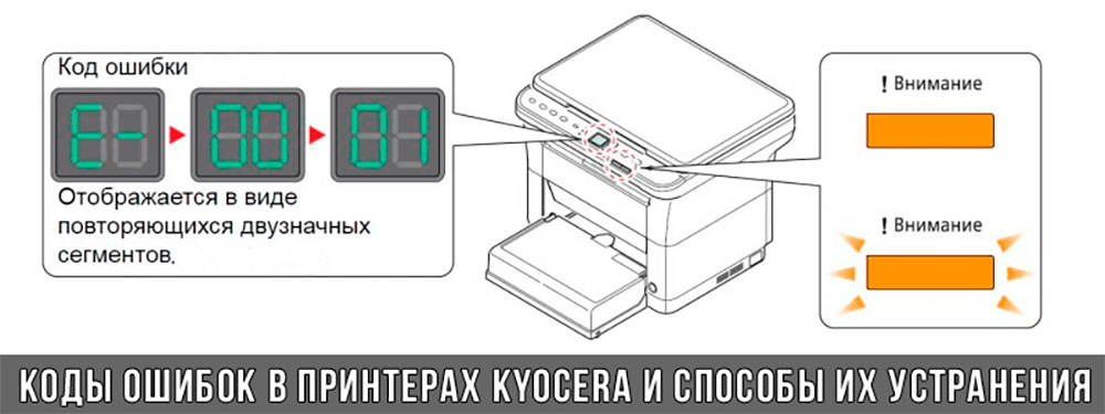
E-0001
В принтере установлен совместимый картридж или чип расходника был поврежден. Проблема решается несколькими способами:
1. установка оригинального картриджа;
2. замена поврежденного чипа;
3. прошивка принтера – затем в печатающее устройство можно будет установить любой картридж неограниченное количество раз;
4. сброс ошибки – зажмите на несколько секунд кнопки «Режим» и «Сброс».
E-0002
Регион используемого картриджа не соответствует характеристикам принтера. Проблема решается несколькими способами:
1. установка соответствующего региону принтера картриджа;
3. прошивка принтера.
E-0003
Память печатающего устройства заполнена. Распечатайте уже отсканированные документы или сбросьте операцию соответствующей кнопкой.
E-0007
В картридже закончился тонер. Замените картридж на новый оригинальный, совместимый или заправьте расходник.
E-0008
Одна из крышек принтера не закрыта. Захлопните заднюю и переднюю крышки принтера, ощутив характерный щелчок.
E-0009
Лоток с отпечатками переполнен. Извлеките распечатанные листы с бумагой, а затем возобновите печать кнопкой «Старт».
E-0012
Память принтера заполнена. Измените разрешение печати в меньшую сторону – до 600 dpi.
E-0014
Установлена бумага такого формата, который принтер не поддерживает. Замените бумагу листами совместимого формата.
Иногда функционал принтера может быть ограничен на софтверном уровне.
Чтобы расширить диапазон форматов, мы рекомендуем обновить ПО печатающего устройства.
E-0015
1. У принтера отсутствует питание.
2. Сетевой кабель не подключен.
3. На персональном компьютере отсутствует драйвер.
Проверьте целостность сетевого кабеля.
При необходимости установите драйвер.
E-0018
Выбранный файл отсутствует в очереди на печать. Сбросьте операцию, нажав на кнопку «Сброс». Затем выберите новый файл и продолжите печать.
E-0019
Формат печати не поддерживается принтером. Сбросьте операцию, нажав на кнопку «Сброс».
J-0511
Бумагу зажевало. Аккуратно извлеките остатки бумаги из корпуса принтера.
PF
Отсутствует бумага во входном лотке. Установите бумагу во входной лоток и возобновите печать, нажав на кнопку «Старт».
Устранение ошибок у принтеров Kyocera в сервисном центре
Возможная причина
0030
0100
Неисправна Flash-память или плата PWB.
0120
Неисправна Flash-память.
0190
Неисправна Flash-память или плата PWB.
0630
Неисправна PWB-плата.
2000
1. Неисправна PWB-плата;
2. неисправен соединительный кабель или нарушена целостность соединения контактов;
3. неисправен привод или его отдельные узлы.
3100
1. Неисправен соединительный кабель или нарушена целостность соединения контактов;
2. неисправен датчик положения;
3. неисправен привод сканера;
4. неисправна PWB-плата.
3300
1. Неисправен соединительный кабель или нарушена целостность соединения контактов;
2. неисправен датчик CIS;
3. неисправна PWB-плата.
3500
Неисправна PWB-плата.
4000
1. Неисправен соединительный кабель или нарушена целостность соединения контактов;
2. неисправен привод;
3. неисправна PWB-плата.
4200
1. Неисправен соединительный кабель или нарушена целостность соединения контактов;
2. неисправна PWB-плата и отдельные компоненты.
6000
1. Неисправен соединительный кабель или нарушена целостность соединения контактов;
2. неисправен термостат;
3. неисправен нагреватель фьюзера;
4. неисправна PWB-плата и отдельные компоненты.
6020
1. Неисправна PWB-плата и отдельные компоненты;
2. выявлен дефект у термистора.
6030
1. Неисправен соединительный кабель или нарушена целостность соединения контактов;
2. выявлен дефект у термистора;
3. неисправен термостат;
4. неисправна PWB-плата и отдельные компоненты.
6400
1. Неисправен соединительный кабель или нарушена целостность соединения контактов;
2. неисправна PWB-плата и отдельные компоненты.
F000
Неисправна PWB-плата и отдельные компоненты.
F020
Неисправна PWB-плата.
F040
Неисправна PWB-плата.
F05D
1. Неисправно программное обеспечение привода;
2. неисправна PWB-плата и отдельные компоненты.
Попытались самостоятельно устранить ошибку на принтере Kyocera, но проблемы с печатью остались нерешенными? Сервисный центр МосТонер – круглосуточный бесплатный выезд мастера в пределах МКАД. Вы платите только за результат!
Коды ошибок Kyocera ecosys m2040dn, 2040, kyocera m2040dn ошибка, kyocera 2040 ошибка, коды ошибок kyocera m2040dn, сброс ошибки, 7990, C7990, код ошибки, как сбросить ошибку, сброс
kyocera m2040dn как сбросить ошибку, kyocera m2040 ошибка, kyocera 2040 ошибка C7990, kyocera m2040dn ошибка, сброс, ECOSYS 2040 код ошибки, сброс, Коды ошибок Kyocera Ecosys 2040, kyocera 2040 ошибка C0030, C0070, C0100, C0120, C0130, C0140, C0150, C0160, C0170, C0180, C0190, C0500, C0510, C0530, C0540, C0800, C0830, C0840, C0870, C0920, C0970, C1810, C1820, C2000, C2010, C2600, C2610, C3100, C3200, C3210, C3300, C3310, C3500, C4000, C4010, C4201, C6000, C6020, C6030, C6050, C6200, C6220, C6230, C6250, C6400, C6600, C6610, C6650, C7220, C7800, C7990, CF000, CF010, CF020, CF040, CF041, CF050, CF051 0030, 0070, 0100, 0120, 0130, 0140, 0150, 0160, 0170, 0180, 0190, 0500, 0510, 0530, 0540, 0800, 0830, 0840, 0870, 0920, 0970, 1810, 1820, 2000, 2010, 2600, 2610, 3100, 3200, 3210, 3300, 3310, 3500, 4000, 4010, 4201, 6000, 6020, 6030, 6050, 6200, 6220, 6230, 6250, 6400, 6600, 6610, 6650, 7220, 7800, 7990, F000, F010, F020, F040, F041, F050, F051
Решил сделать небольшую шпаргалку с кодами ошибок к принтерам Kyocera FS 1030/1035, 1130/1135, 2030/2035. Может быть и вам пригодится.
Коды ошибок Kyocera FS 1030-1035/2030-2035
В серии Kyocera FS код ошибки выводится в формате С#### или F###. Небольшая сводная таблица по ним:
| Код | Значение | Описание | Причина | Решение |
|---|---|---|---|---|
| C0030 | Системная ошибка в управлении факсом | Обработка при помощи программного обеспечения факса была отключена из за проблем с оборудованием | Неисправность в системе управления факсом PWB | Заменить систему управления факсом PWB |
| C0070 | Обнаружена несовместимость платы управления PWB | Обнаружена несовместимость при первичной инициализации системы управления факсом PWB. Никакие команды связи не проходят. | Дефект программного обеспечения факса | Установить программное обеспечение для факса |
| C0100 | Ошибка при резервном копировании памяти устройства | Неисправна флеш память | Заменить плату управления PWB | |
| C0120 | Ошибка данных MAC адреса | Неисправность в плате управления PWB | Заменить плату управления PWB | |
| C0130 | Ошибка чтения/записи при резервном копировании | Неисправна флеш память | Заменить плату управления PWB | |
| C0140 | Ошибка при резервном копировании данных | Неисправна флеш память | Заменить плату управления PWB | |
| C0150 | Ошибка EEPROM платы управления PWB | Обнаружена ошибка связи PWB EEPROM (U17) | Неправильная установка PWB EEPROM (U17) | Проверить установку EEPROM (U17) и при необходимости исправить |
| C0170 | Ошибка счетчика | 1. Неисправность control PWB. |
2. Повреждения данных PWB EEPROM (U17)
1. Заменить плату управления PWB.
2. Обратиться в сервис обслуживания
C0180 Номер аппарата не совпадает Основной номер и номер двигателя не совпадают 1. Основная PWB или PWB двигателя была заменена.
2. Повреждения данных PWB EEPROM (U17)
1. U004 Задать номер.
2. Обратиться в сервис обслуживания
C0420 Ошибка связи с системой подачи бумаги Ошибка коммуникации между платой PWB и дополнительным устройством подачи бумаги 1. Неправильная установка устройства подачи бумаги
2. Повреждение провода между платой PWB (YC30) и интерфесным разъемом устройства подачи, либо разъем подключен неправильно.
3. Неисправен кабель между PF основной PWB и подачей бумаги, либо разъем не вставлен. Плата PF неисправна.
4. Неисправность control PWB
1. Еще раз внимательно прочитайте инструкцию по установке.
2. Убедитесь, что разъем подключен, а кабель не поврежден. При необходимости — замените.
3. Убедитесь, что разъем подключен, а кабель не поврежден.Заменить печатную плату.
4. Заменить плату управления PWB.
C0830 Ошибка контрольной суммы прошивки FAX control PWB Произошла ошибка контрольной суммы программы управления FAX control PWB 1. Дефект программного обеспечения факса.
2. Неисправность в системе управления факсом PWB
1. Установить программное обеспечение для факса.
2. Заменить плату управления факсом PWB
C0840 Неисправность RTС Расхождение во времени между RTC и текущим пять и более лет. 1. Неисправность control PWB
2. Отсоединена батарея.
1. Заменить плату управления PWB.
2. Визуально проверить и при необходимости исправить.
C0870 Проблема передачи данных большой емкости между FAX control PWB и control PWB Не выполняется передача данных между FAX control PWB и control PWB, даже при повторе через заданный промежуток Неправильная установка FAX control PWB
Переставить FAX control PWB C0920 Ошибка файловой системы факса Резервное копирование данных не производится по причине ошибки файловой системы флеш-памяти Неисправность в системе управления факсом PWB Заменить плату управления факсом PWB C2000 Ошибка главного двигателя Главный двигатель не выходит на готовность в течение 2 секунд после включения 1. Неисправен кабель между основным двигателем (CN1) и платой PWB (YC17) или разъем вставлен неправильно.
2. Неисправен привод основного двигателя.
3. Неисправен двигатель.
4. Неисправность control PWB
1. Вставьте разъем. Проверьте целостность кабеля.
2. Проверьте плавность вращения роликов и шестерней. При необходимости смажьте. Убедитесь в отсутсвии разрывов передач.
C2610 Ошибка дигателя устройства подачи бумаги Двигатель устройства подачи бумаги лотка 2 не выходит на готовность более чем через 2 секунды после включения. Неисправность кабеля между двигателем устройства подачи бумаги и control PWB (YC4). Вставьте разъем. Проверьте целостность кабеля (Обратитесь к инструкции) C2620 Ошибка дигателя устройства подачи бумаги Двигатель устройства подачи бумаги лотка 3 не выходит на готовность более чем через 2 секунды после включения. Неисправность кабеля между двигателем устройства подачи бумаги и control PWB (YC4). Вставьте разъем. Проверьте целостность кабеля (Обратитесь к инструкции) C3100 Ошибка исходного положения ISU 1. Неисправность FFC между CCD PWB (YC1) и control PWB (YC8).
2. Неисправность FFC между control PWB (YC6) и сканера WPB (YC103) или неправильная установка FCC.
3. Неисправность датчика исходного положения.
4. Неисправность кабеля между двигателем ISU и сканером PWB (YC104) или разъем вставлен неправильно.
1. Заменить блок сканера ISU
2. Переставить FFC. Проверить на разрыв, при необходимости заменить.
3. Заменить датчик.
4. Вставьте разъем. Проверьте целостность кабеля.
C3200 Ошибка лампы экспозиции Лампа экспозиции не включается 1. Повреждения FFC между сканером PWB (YC103) и control PWB (YC6), либо некорректная установка FFC.
2. Повреждения FFC между CCD PWB (YC1) и control PWB (YC8).
3. Неисправен кабель между CCD PWB (YC3) и LED приводом PWB (YC1) либо разъем не подключен.
4. Неисправен кабель между LED приводом PWB (YC2) и лампой экспонирования.
5. Лампа экспонирования вышла из строя.
6. Неисправен светодиодный привод.
1. Переустановите FFC. Проверьте целостность, при необходимости замените.
2. Заменить блок сканера.
3. Убедитесь, что разъем подключен, а кабель не поврежден. При необходимости — замените.
4. Убедитесь, что разъем подключен, а кабель не поврежден. При необходимости — замените.
5. Заменить лампу.
6. Заменить привод.
C3300 Ошибка AGC 1. Повреждения FFC между CCD PWB (YC1) и control PWB (YC8).
2. Лампа экспонирования вышла из строя.
3. Неисправность CCD PWB
4. Неисправность control PWB
1. Заменить блок сканера.
2. Заменить лампу.
3. Заменить CCD PWB
4. Заменить control PWB
C3500 Ошибка связи CPU — ASIC (CCD PWB) Обнаружен код ошибки 1. Повреждения FFC между CCD PWB (YC1) и control PWB (YC8).
2. Неисправность CCD PWB.
3. Неисправность control PWB
1. Заменить блок сканера (ISU).
2. Заменить CCD PWB
3. Заменить control PWB
C4000 Ошибка полигон-мотора (блока лазерного сканера) Полигон-мотор не выходит на готовность после 6 секунд после включения. 1. Поврежден кабель между полигон-мотором и control PWB (YC10) или разъем не вставлен.
2. Неисправен блок лазерного сканера.
3. Неисправность control PWB
1. Убедитесь, что разъем подключен, а кабель не поврежден. При необходимости — замените.
2. Заменить блок сканера.
3. Заменить control PWB
C4200 Ошибка BD (блока лазерного сканера) 1. BD датчик не обнаруживает лазерный луч из-за скопления конденсата на зеркале.
2. Неисправен блок лазерного сканера.
1. Выключите питание машины минимум на 30 минут, затем снова включите, если это не помогает необходимо менять блок сканера.
2. Заменить блок сканера.
C6000 Выход из строя термо-элемента (фьюзера) Температура фьюзера не поднимается после включения устройства. 1. Плохой контакт клемм термистора фьюзера.
2. Плохой контакт в местах подключения нагревателя термоблока.
3. Термисторы фьюзера установлены неправильно.
4 . Срабатывает термореле
5. Нагреватель фьюзера установлен неправильно
6. Выход из строя термо-элемента
1. Проверьте контакты.
2. Проверьте контакты.
3. Заменить блок закрепления
4. Заменить блок закрепления
5. Заменить блок закрепления
6. Заменить блок закрепления
C6020 Слишком высокая температура фьюзера Термистор фьюзера обнаружил аномально высокую температуру. Пробой термистора фьюзера Заменить блок закрепления C6030 Поврежден шлейф термистора термоэлемента Значени на входе термистора равно 0 1. Плохой контакт в клеммах термистора.
2. Неисправен шлейф термистора
3. Термистор установлен некорректно
4. Срабатывает термореле
Проверить контакты
Заменить блок закрепления
C6400 Ошибка пересечения нуля Сигнал пересечения нуля не достигает контрольной платы за указанное время 1. Неисправен кабель между PWB высокого напряжения(YC202) и control PWB (YC23) или разъем не вставлен
2. Дефект соединения между источником питания PWB (YC103) и PWB высокого напряжения (YC201)
3. Неисправен источник питания PWB
4. Неисправность control PWB
1. Переподключите коннектор.Убедитесь что кабель не поврежден.
2. Переподключите коннектор
3. Заменить источник питания
4. Заменить control PWB
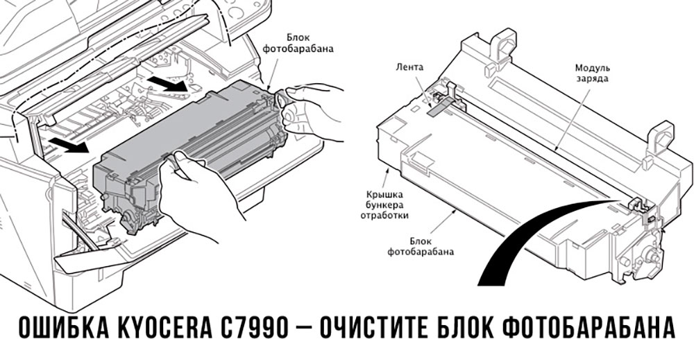
C7990 Бункер отработки переполнен Датчик тонера обнаружил, что бункер для отработки переполнен 1. Бункер отработки драм-юнита переполнен.
2. Неисправен датчик отработки
3. Неисправность control PWB
1. Перезагрузите машину кратковременным выключением питания, если ошибка не исчезла замените драм-юнит.
2. Замените датчик.
3. Заменить control PWB
4. Очистите драм юнит (инструкция по очистке бункера отработанного тонера)
F000 Ошибка связи control PWB — панель управления PWB 1. Неисправность соединения панели управления PWB (YC1) и control PWB (YC7).
2. Неисправность панели управления
3. Неисправность control PWB
1. Переподключите коннектор.Убедитесь что кабель не поврежден.
2. Замените панель.
3. Заменить control PWB
F020 Ошибка контрольной суммы RAM control PWB 1. Неисправность основной микросхемы памяти (ОЗУ) на главной плате управления PWB
2. Неисправность платы расширения памяти (DIMM)
1. Перезагрузите машину кратковременным выключением питания, если ошибка не исчезла, замените control PWB
2. Замените плату расширения (DIMM)
F040 Ошибка связи control PWB двигателя Обнаружена ошибка связи Неисправность control PWB Перезагрузите машину кратковременным выключением питания, если ошибка не исчезла, замените control PWB F041 Ошибка связи между гланой платой управления и платой управления сканером Обнаружена ошибка связи Неисправна главная плата управления или управления сканером Перезагрузите машину кратковременным выключением питания, если ошибка не исчезла, замените control PWB или scanner PWB F050 Ошибка контрольной суммы платы управления двигателем 1. Такие ошибки могут происходить при обновлении прошивки control PWB
2. Неисправность control PWB
1. Скачайте прошивку снова
2. Перезагрузите машину кратковременным выключением питания, если ошибка не исчезла, замените control PWB
F186 Ошибка управления видеоданными главной панели управления Неисправность control PWB Перезагрузите машину кратковременным выключением питания, если ошибка не исчезла, замените control PWB
Надеюсь вам пригодится эта табличка. Меня она иногда сильно выручает.
Источник
Правила форума
Картинки и фотографии (если они нужны в сообщении) надо загружать только как вложения к своему сообщению (через кнопку Добавить файлы). Тогда картинки будут автоматически отображаться в сообщении.
-
- 2 Ответы
- 609 Просмотры
-
Последнее сообщение

18 авг 2022, 10:12
-
- 3 Ответы
- 221 Просмотры
-
Последнее сообщение
15 авг 2022, 14:32
-
- 2 Ответы
- 497 Просмотры
-
Последнее сообщение

17 янв 2022, 16:23
-
- 13 Ответы
- 2792 Просмотры
-
Последнее сообщение
03 фев 2022, 15:54
-
- 3 Ответы
- 855 Просмотры
-
Последнее сообщение

03 фев 2022, 14:59


Японская компания Kyocera производит высококачественные лазерные принтеры и МФУ для офисной печати. Их продукция одна из самых востребованных на сегодняшний день. Ведь печатающие устройства Kyocera характеризуются высокой надежностью, износостойкостью и большим сроком эксплуатации. Однако даже их изделия не являются вечными. Со временем принтеры Kyocera начинают сбоить.
К счастью, оргтехника Kyocera оснащена системой самодиагностики (так же, как и струйные принтеры Canon). Поэтому, в случае возникновения проблемы, устройство самостоятельно выявит уязвимое место и сообщит Вам об этом миганием соответствующего индикатора на панели управления либо кодом ошибки, выведенным на дисплей принтера.
Если Вы не являетесь мастером по обслуживанию принтеров и МФУ Kyocera, то, чтобы понять, о чем сообщает печатающее устройство, Вам потребуется расшифровать указанный им код. Для этого мы добавили в статью таблицу кодов ошибок лазерных принтеров Kyocera серии FS и не только.
Коды ошибок принтеров и МФУ Kyocera, которые можно исправить самостоятельно
|
Код ошибки |
Значение ошибки |
Решение проблемы |
|
E-0001 (E1) |
Поврежден чип картриджа либо установлен неоригинальный картридж. |
Замените установленный картридж оригинальной версией изделия. Если хотите сэкономить, тогда купите и установите новый чип на картридж или перепрошейте принтер Kyocera. Однако предварительно не помешает попробовать сбросить ошибку соответствующей комбинацией клавиш (как это сделать, читайте в статье «Сброс ошибки установки неоригинального картриджа в принтерах Kyocera»). |
|
E-0002 (E2) |
Регион использования картриджа и принтера не совпадают. |
Замените чип или прошейте принтер Kyocera. |
|
E-0003 (E3) |
Заполнена память принтера или МФУ Kyocera. |
Отпечатайте ранее отсканированные листы или очистите очередь печати нажатием кнопки Стоп/Сброс (ранее отсканированные листы также удалятся из памяти принтера, даже если они еще не были распечатаны). |
|
E-0007 (E7) |
Тонер-картридж Kyocera израсходовал ресурс красящего вещества. |
Замените или заправьте картридж Kyocera (если используете совместимый или перезаправленный расходник, то после установки его в принтер не забудьте сбросить ошибку зажатием на 3-5 секунды кнопок [Ок] и [Сброс/Стоп]). |
|
E-0008 (E8) |
Открыта крышка принтера либо не работает датчик закрытия крышек устройства. |
Откройте и еще раз закройте переднюю и заднюю крышку принтера. Во время закрытия Вы должны услышать характерный щелчок. Если не помогло, то причина в неисправности датчика. |
|
E-0009 (E9) |
Лоток приема бумаги полон. |
Уберите все отпечатанные листы бумаги из выходящего лотка. Чтобы возобновить печать, нажмите кнопку [Старт]. |
|
E-0012 (E12) |
Ошибка памяти принтера Kyocera. |
Попробуйте уменьшить разрешение печати. Скорее всего, формат создаваемого отпечатка не соответствует возможностям принтера. |
|
E-0014 (E14) |
Установлен неверный формат бумаги (неподдерживаемый принтером Kyocera). |
Поменяйте бумагу на поддерживаемую принтером либо смените ее формат в настройках печати. Попробуйте обновить программное обеспечение. Возможно, это расширит поддерживаемые принтером Kyocera форматы. |
|
E-0015 (E15) |
Устройство не подключено к электрической сети либо на компьютере нет (не работает) драйвера принтера Kyocera. |
Проверьте подключение печатающего аппарата к электрической сети, а также целостность кабеля. Если ошибка не исчезает, скачайте драйвер принтера Kyocera и установите его на компьютер. |
|
E-0017 (E17) |
Ошибка передачи данных. |
Проверьте подключение принтера к компьютеру. Кабель не должен быть длиннее 5 метров, а также обязан поддерживать стандарт USB 2.0. Кроме того, переустановите драйвер принтера и утилиту Kyocera Client Tool. |
|
E-0018 (E18) |
Очередь печати заполнена. |
Очистите очередь печати нажатием кнопки [Сброс] либо через драйвер принтера. |
|
E-0019 (E19) |
Неверный формат печати. |
Отмените печать нажатием кнопки [Стоп/Сброс]. Выберите в настройках принтера соответствующий режим печати, а также установите в лоток поддерживаемый принтером формат бумаги. |
|
J-0000 (jam0000) |
Замятие бумаги за задней крышкой. |
Откройте крышку и извлеките бумагу. Проверьте надежность крепления бумаги в лотке, а также принтер на наличие посторонних предметов. Еще причина может быть в пружине выходного флажка. Если она растянулась, то может плохо работать фиксатор. Также проблема может быть из-за печки, сделайте ее ревизию, переборку и смазку. |
|
J-0501 (jam0501) |
Бумага застряла в принтере Kyocera |
Извлеките замятую бумагу. Проверьте надежность установки бумаги во входной лоток. Проверьте целостность роликов протяжки бумаги, а также принтер на наличие посторонних предметов. Если не помогло, стоит внимательно осмотреть ребра на направляющей пластине. На них могут образоваться сколы, трещины и заусенцы. Их можно слегка подчистить наждачной бумагой (нулевкой). |
|
J-0511 (jam0511) |
Принтер Kyocera замял бумагу. |
Извлеките замятую бумагу и повторите печать. Если проблема не исчезла, несите принтер в сервис. Скорее всего, изношен ролик протяжки бумаги. |
|
C7990 |
Бункер драм-картриджа (блока фотобарабана) заполнен отработанным тонером либо неисправен счетчик отработки красящего вещества. Еще проблема может быть в главной плате PWB. |
Осуществите чистку драм-картриджа (блока фотобарабана). Если проблема в датчике или плате, то нужно отнести принтер в СЦ на диагностику. |
|
F248 |
Ошибка обработки отпечатываемого материала. |
Перезагрузите принтер. Уберите неподдерживаемые спецсимволы из отпечатка. Обновите ПО принтера Kyocera. Смените режим работы принтера с PDL на GDI (Пуск -> Принтеры -> Свойства -> Параметры устройства). |
|
PF |
Отсутствует бумага в лотке подачи. |
Загрузите листы бумаги во входной лоток. Если принтер по-прежнему не печатает, значит нужно искать проблему в чем-то другом. |
|
1101 |
Ошибка сканирования через сеть из-за неправильного имени SMTP сервера. |
Пропишите DNS-адреса помимо прочих настроек печати по сети. |
|
1102 |
Некорректная настройка сканера для работы через сеть |
Зайдите в Web-панель управления принтером (нужно в адресную строку браузера ввести iP принтера Kyocera). Далее в зависимости от модели введите логин и пароль (Admin/Admin или просто admin00 без логина). Далее следуйте инструкции:
Логин и пароль нужны обязательно, если их нет, то следует создать. |
|
2101 |
Ошибка передачи данных при сканировании через сеть. |
Правильно настройте параметры (как для ошибки 1102), только предварительно отключите на ПК антивирус и брандмауэр. |
Если Вы испытали все способы, но не смогли убрать ошибку, то следует нести печатающее устройство в сервисный центр. Кроме того, есть ряд ошибок (высвечиваемых на дисплее принтера), которые нельзя устранить в домашних условиях. Соответствующие коды ошибок принтеров Kyocera представляем в очередной таблице.
Коды ошибок принтеров и МФУ Kyocera, которые нужно устранять в сервисном центре
|
Код ошибки |
Значение ошибки |
Решение проблемы |
|
0030 |
Неисправность платы управления факсом принтера. |
Замена платы. |
|
0100 |
Неисправность платы управления или флеш-памяти принтера. |
Замена платы. |
|
0120 |
Ошибка чтения mac-адреса из-за неисправности флеш-памяти принтера. |
Замена платы. |
|
0190 |
Неисправность платы управления или флеш-памяти принтера. |
Замена платы. |
|
0630 |
Неисправность платы управления принтера. |
Замена платы. |
|
1020 |
Неисправность мотора, привода или отсутствие контакта. |
Разборка принтера и замена изношенных частей. Проверка надежности подключений, замена разорванных (прогоревших) кабелей. Ремонт или замена привода мотора. |
|
1040 |
Неисправность мотора, привода или отсутствие контакта. |
Разборка принтера и замена изношенных частей. Проверка надежности подключений, замена разорванных (прогоревших) кабелей. Ремонт или замена привода мотора. |
|
2000 |
Неисправность главной платы управления, соединительного кабеля или привода принтера. |
Проверить ремни, шестерни и ролики привода. Смазать или заменить, если есть дефекты. Заменить привод или главную плату. |
|
3100 (C3100) |
Неисправность главной платы, привода сканера, датчика положения или нарушение целостности соединений. |
Проверить наличие разрывов и отсутствия контакта. Смазать или заменить изношенные элементы привода. Заменить привод, главную плату, датчик или соединительный кабель. Если Вам повезло, то возможно забыли отключить фиксатор блока сканера. |
|
3101 |
Сетевой кабель не подсоединен, или нарушена работа концентратора. Еще может быть из-за наличия вирусов в системе или неправильно заданным параметрам сервера SMTP. |
Проверить соединения, правильно настроить параметры сети. |
|
3300 |
Неисправность главной платы, датчика CIS или соединительного кабеля. |
Проверить контакты, заменить плату или датчик. |
|
3500 |
Неисправность главной платы или нарушение соединения контактов. |
Проверить контакты, заменить плату. |
|
4000 (C4000) |
Неисправность главной платы, привода сканера или нарушение соединений. Однако чаще всего ошибка лазера. |
Проверить контакты, заменить плату или привод блока сканера. Почистить лазер, смазать ось полигон-мотора, либо полностью заменить блок лазера. |
|
4200 |
Неисправность главной платы, блока сканера или датчика BD. |
Отключить питание принтера на 30 минут. Если не помогло, то следует заменить привод сканера или главную плату принтера. |
|
6000 (С6000) |
Неисправность главной платы, термостата, печки или нарушение соединения контактов. |
Проверить и поправить контакты. Заменить фьюзер. Ремонт или замена печки, термодатчика, термопредохранителя и т.д. |
|
6020 |
Сгорание термистора или главной платы. |
Замена термистора или главной платы. |
|
6030 |
Неисправность главной платы, термостата или термистора. Возможно, причина в отсутствии контакта. |
Проверить соединения. Заменить плату, термостат или термистор. |
|
6400 |
Неисправность главной платы, отсутствие питания или контакта. |
Заменить плату или источник питания. |
|
F000 |
Неисправность главной платы или отсутствие контакта. |
Проверить соединение ремня безопасности. Заменить ремень или плату управления. |
|
F020 |
Неисправность элементов памяти принтера. |
Перезагрузить принтер. Если ошибка не устранилась – заменить плату управления. |
|
F040 |
Неисправность главной платы принтера. |
Перезагрузить принтер. Если ошибка не устранилась – заменить плату управления. |
|
F05D |
Неисправность главной платы. Сбой программного оборудования привода. Проблемы с прошивкой принтера Kyocera. |
Перезагрузить принтер. Если ошибка не устранилась – заменить плату управления. Перепрошить принтер Kyocera. |
|
F245 F246 F247 F375 |
Принтер Kyocera заблокирован из-за проблемы, вызванной отказом источника питания. |
Нужно перепрошить принтер специальной сервисной микропрограммой. |
Обратите внимание: Если у печатающего устройства нет дисплея, то определить проблему можно по светодиодным индикаторам, встроенным в панель управления принтером. Например, у Kyocera Ecosys P2135D нужно сосчитать количество миганий индикаторов красного цвета и таким образом определить число, указывающее на ту или иную ошибку. В свою очередь, у модели Kyocera FS-1040 все зависит от темпа мигания светодиода с надписью «Внимание!» («Attention!»):
- Мигает медленно – указывает на отсутствие бумаги в лотке или тонера в картридже.
- Мигает быстро – оповещает о проблеме с памятью устройства, переполненном лотке или замятии бумаги, а также об использовании неоригинальных расходных материалов.
- Горит постоянно – говорит о проблемах с картриджем или фотобарабаном либо указывает на открытые крышки принтера.
Чтобы потребитель мог наверняка определить проблему, рекомендуем использовать утилиту Kyocera Client Tool, которая идет в комплекте с драйверами принтера.
Ваше Имя:
Ваш вопрос:
Внимание: HTML не поддерживается! Используйте обычный текст.
Оценка:
Плохо
Хорошо
Введите код, указанный на картинке:


Модератор: vetal
-
-
Kyocera FS-1120d индикатор «Нет бумаги»
vs-dos в форуме Принтеры, МФУ, факсы, копиры формата A4
- 11
- 15142
СТРОНЦИЙ

Вт ноя 02, 2021 2:24 pm
-
Kyocera FS-1120d индикатор «Нет бумаги»
-
-
Kyocera 1035 «бледная» печать
srMax в форуме Принтеры, МФУ, факсы, копиры формата A4
- 2
- 13949
srMax
Пт янв 23, 2015 2:49 pm
-
Kyocera 1035 «бледная» печать
-
-
[SCANNER ERROR] Lamp Error Kyocera FS-1016
мастерчип в форуме Принтеры, МФУ, факсы, копиры формата A4
- 3
- 6645
Усатый Полосатый
Вс окт 28, 2018 11:08 pm
-
[SCANNER ERROR] Lamp Error Kyocera FS-1016
-
-
Taskalfa 180 ошибка «Е» и «Встряхните картр. с тонером»
manik.76 в форуме Принтеры, МФУ, копиры формата A3
- 3
- 9650
dviz
Пн фев 20, 2017 1:35 pm
-
Taskalfa 180 ошибка «Е» и «Встряхните картр. с тонером»
-
-
Kyocera taskalfa 3501 «открыта крышка основного блока»
Юрий Яраскин в форуме Принтеры, МФУ, копиры формата A3
- 3
- 2891
Goldwater
Пт сен 10, 2021 1:31 pm
-
Kyocera taskalfa 3501 «открыта крышка основного блока»
Вернуться в Принтеры, МФУ, факсы, копиры формата A4
Кто сейчас на форуме
Сейчас этот форум просматривают: нет зарегистрированных пользователей и гости: 75
- Code: C0070
- Description: FAX PWB incompatible detection error
- Causes: Abnormal detection of FAX control PWB incompatibility in the initial communication with the FAX control PWB, any normal communication command is not transmitted.
- Remedy: 1 Checking the FAX PWB The incompatible FAX PWB is installed. Install the FAX PWB for the applicable model. 2 Firmware upgrade The FAX firmware is faulty. Reinstall the FAX firmware. 3 Replacing the main PWB The main PWB is faulty. Replace the main PWB.
- Code: C0100
- Description: Backup memory device error
- Causes: An abnormal status is output from the flash memory.
- Remedy: 1 Resetting the main power The flash memory does not operate properly. Turn off the power switch and unplug the power plug. After 5s passes, reconnect the power plug and turn on the power switch. 2 Checking the main PWB The connector or the FFC is not connected properly. Or, the wire, FFC, the PWB is faulty. Clean the terminal of the connectors on the main PWB, reconnect the connector of the wire, and reconnect the FFC terminal. If the wire or the FFC is faulty, repair or replace them. If not resolved, replace the main PWB.
- Code: C0120
- Description: MAC address data error
- Causes: The MAC address data is incorrect.
- Remedy: 1 Resetting the main power The flash memory does not operate properly. Turn off the power switch and unplug the power plug. After 5s passes, reconnect the power plug and turn on the power switch. 2 Checking the MAC address The MAC address is incorrect. Replace the main PWB when the MAC address is not indicated on the network status page.
- Code: C0130
- Description: Backup memory reading/writing error
- Causes: The reading or writing into the flash memory is unavailable.
- Remedy: 1 Resetting the main power The flash memory does not operate properly. Turn off the power switch and unplug the power plug. After 5s passes, reconnect the power plug and turn on the power switch. 2 Checking the main PWB The connector or the FFC is not connected properly. Or, the wire, FFC, the PWB is faulty. Clean the terminal of the connectors on the main PWB, reconnect the connector of the wire, and reconnect the FFC terminal. If the wire or the FFC is faulty, repair or replace them. If not resolved, replace the main PWB.
- Code: C0140
- Description: Backup memory data error
- Causes: The flash memory data read at the initial start-up is faulty
- Remedy: 1 Resetting the main power The flash memory does not operate properly. Turn off the power switch and unplug the power plug. After 5s passes, reconnect the power plug and turn on the power switch. 2 Checking the main PWB The connector or the FFC is not connected properly. Or, the wire, FFC, the PWB is faulty. Clean the terminal of the connectors on the main PWB, reconnect the connector of the wire, and reconnect the FFC terminal. If the wire or the FFC is faulty, repair or replace them. If not resolved, replace the main PWB.
- Code: C0150
- Description: Engine EEPROM reading / writing error
- Causes: 1. Continuous five times detection of no response from the device for 5ms or more on reading / writing. 2. Data read twice do not match continuous 8 times. 3. Writing data and reading data do not match continuous 8 times.
- Remedy: 1 Resetting the main power The EEPROM on the engine PWB does not operate properly. Turn off the power switch and unplug the power plug. After 5s passes, reconnect the power plug and turn on the power switch. 2 Checking the EEPROM on the engine PWB The EEPROM is not properly attached. Reattach the EEPROM on the engine PWB. 3 Replacing the EEPROM The EEPROM is faulty. 1. Print Maintenance Report at U000 beforehand. 2. Replace the EEPROM on the engine PWB. C6990 appears when turning the power on. Execute U169 at that state. 3. Then, print Maintenance Report at U000. Compare the setting values with Maintenance Report printed before and change the different values. (Target maintenance mode: U063, U100, U127, U140, U161, U465, U468 and U901, etc.) 4. Check the output image and adjust the image at U410, U411, etc. if necessary. 4 Replacing the engine PWB The engine PWB is faulty. Replace the engine PWB.
- Code: C0160
- Description: EEPROM data error
- Causes: The data read from the EEPROM is judged as abnormal.
- Remedy: 1 Resetting the main power The EEPROM on the engine PWB does not operate properly. Turn off the power switch and unplug the power plug. After 5s passes, reconnect the power plug and turn on the power switch. 2 Executing U021 The storage data in the EEPROM on the engine PWB is faulty. Execute U021. 3 Replacing the EEPROM The EEPROM is faulty. 1. Print Maintenance Report at U000 beforehand. 2. Replace the EEPROM on the engine PWB. C6990 appears when turning the power on. Execute U169 at that state. 3. Then, print Maintenance Report at U000. Compare the setting values with Maintenance Report printed before and change the different values. (Target maintenance mode: U063, U100, U127, U140, U161, U465, U468 and U901, etc.) 4. Check the output image and adjust the image at U410, U411, etc. if necessary. 4 Replacing the engine PWB The engine PWB is faulty. Replace the engine PWB.
- Code: C0170
- Description: Charger count error
- Causes: 1. Errors are detected in both backup memory of the engine PWB charge counter and main PWB charge counter. 2. Main PWB counter data and engine PWB counter date are faulty
- Remedy: 1 Replacing the main PWB The main PWB is faulty. Replace the main PWB and execute U004 2 Replacing the EEPROM on the engine PWB The EEPROM is faulty. 1. Print Maintenance Report at U000 beforehand. 2. Replace the EEPROM on the engine PWB. C6990 appears when turning the power on. Execute U169 at that state. 3. Then, print Maintenance Report at U000. Compare the setting values with Maintenance Report printed before and change the different values. (Target maintenance mode: U063, U100, U127, U140, U161, U465, U468 and U901, etc.) 4. Check the output image and adjust the image at U410, U411, etc. if necessary. 3 Replacing the engine PWB The engine PWB is faulty. Replace the engine PWB.
- Code: C0180
- Description: Machine serial number mismatch
- Causes: The machine serial Nos. in the main PWB and the EEPROM on the engine PWB mismatch when turning the power on.
- Remedy: 1 Checking the machine serial No. of the main PWB The main PWB for the different main unit is installed. Check the machine serial Nos of MAIN and ENGINE at U004, and install the correct main PWB if the MAIN No. differs. 2 Checking the machine serial No. in the EEPROM on the engine PWB The EEPROM for the different main unit is installed. Check the machine serial Nos of MAIN and ENGINE at U004, and install the correct EEPROM on the engine PWB if the ENGINE machine serial No. differs. 3 Replacing the main PWB The main PWB is faulty. When the MAIN machine serial No. differs at U004, replace the main PWB and execute U004. 4 Checking the EEPROM on the engine PWB The EEPROM is faulty. If the machine serial number on the engine PWB is different at U004, reattach the EEPROM. If not repaired, replace the EEPROM on the engine PWB by referring to the following procedures. 1. Print Maintenance Report at U000 beforehand. 2. Replace the EEPROM on the engine PWB. C6990 appears when turning the power on. Execute U169 at that state. 3. Then, print Maintenance Report at U000. Compare the setting values with Maintenance Report printed before and change the different values. (Target maintenance mode: U063, U100, U127, U140, U161, U465, U468 and U901, etc.) 4. Check the output image and adjust the image at U410, U411, etc. if necessary. 5 Replacing the engine PWB The engine PWB is faulty. Replace the engine PWB.
- Code: C0190
- Description: Backup memory device error (Engine)
- Causes: Data from the main unit IC cannot be read out at power-up
- Remedy: 1 Resetting the main power The IC in the engine PWB does not operate normally Turn off the power switch and unplug the power plug. After 5s passes, reconnect the power plug and turn on the power switch. 2 Replacing the engine PWB The engine PWB is faulty. Replace the engine PWB.
- Code: C0500
- Description: Drive lock detected by the engine firmware
- Causes: During the engine steady state control, the main motor drive continued 60 minutes or more (except during the maintenance mode)
- Remedy: 1 Resetting the main power The firmware in the engine PWB does not operate normally Turn off the power switch and unplug the power plug. After 5s passes, reconnect the power plug and turn on the power switch. 2 Replacing the engine PWB The engine PWB is faulty. Replace the engine PWB.
- Code: C0510
- Description: Main charger control error
- Causes: The main charger bias turns on while the drum stops.
- Remedy: 1 Resetting the main power The firmware in the engine PWB does not operate normally Turn off the power switch and unplug the power plug. After 5s passes, reconnect the power plug and turn on the power switch. 2 Replacing the engine PWB The engine PWB is faulty. Replace the engine PWB.
- Code: C0520
- Description: Developer control error
- Causes: The developer bias off is detected during the main charge bias off
- Remedy: 1 Resetting the main power The firmware in the engine PWB does not operate normally Turn off the power switch and unplug the power plug. After 5s passes, reconnect the power plug and turn on the power switch. 2 Replacing the engine PWB The engine PWB is faulty. Replace the engine PWB.
- Code: C0530
- Description: Backup task error
- Causes: No operation 30s or more when monitoring the backup task operation
- Remedy: 1 Resetting the main power The firmware in the engine PWB does not operate normally Turn off the power switch and unplug the power plug. After 5s passes, reconnect the power plug and turn on the power switch. 2 Replacing the engine PWB The engine PWB is faulty. Replace the engine PWB.
- Code: C0800
- Description: Image processing error
- Causes: The print sequence jam (J010x) is detected 2 times continuously.
- Remedy: 1 Checking the image data The image data is faulty. When this issue occurs only when handling the certain image data, check if the image data is faulty. 2 Checking the situation The printing operation of the certain file is faulty. Acquire the job’s log if the phenomenon can be reproduced by specifying the job when the error was detected. 3 Checking the main PWB The connector or the FFC is not connected properly. Or, the wire, FFC, the PWB is faulty. Clean the terminal of the connectors on the main PWB, reconnect the connector of the wire, and reconnect the FFC terminal. If the wire or the FFC is faulty, repair or replace them. If not resolved, replace the main PWB.
- Code: C0830
- Description: FAX PWB flash program area checksum error
- Causes: The program stored in the flash memory on the FAX PWB is broken so it cannot perform.
- Remedy: 1 Resetting the main power The FAX PWB is not connected properly. Turn off the power switch and pull out the power plug. After passing 5s, reattach the FAX PWB and reinsert the power plug. Then, turn on the power switch. 2 Firmware upgrade The firmware is faulty. Reinstall the FAX firmware. 3 Initializing the fax The data in the FAX PWB is faulty. Execute U600 to initialize the FAX. 4 Replacing the FAX PWB The FAX PWB is faulty. Replace the FAX PWB. Step
- Code: C0840
- Description: RTC error
- Causes: • Not communicated with RTC correctly. • RTC data is inconsistent with empty battery.
- Remedy: 1 Setting time and date (RTC) Time and date (RTC) are erased Set Date and Time (RTC) from System Menu 2 Replacing the main PWB The main PWB is faulty, or the backup battery runs out. Replacing the main PWB
- Code: C0870
- Description: PC FAX Image data transmission error
- Causes: Data was not properly transmitted even if the specified times of retry were made when the large volume data is transmitted between the FAX PWB and the main PWB.
- Remedy: 1 Resetting the main power The FAX PWB does not operate properly. Turn off the power switch and pull out the power plug. After passing 5s, reattach the FAX PWB and reinsert the power plug. Then, turn on the power switch. 2 Initializing the fax The data in the FAX PWB is faulty. Execute U600 to initialize the FAX. 3 Firmware upgrade The FAX firmware is faulty. Upgrade the fax firmware to the latest version. 4 Replacing the FAX PWB The FAX PWB is faulty. Replace the FAX PWB. 5 Replacing the main PWB The main PWB is faulty. Replace the main PWB.
- Code: C0920
- Description: FAX file system error
- Causes: The backup data could not be stored since the file system of the flash memory is faulty.
- Remedy: 1 Resetting the main power The FAX PWB does not operate properly. Turn off the power switch and pull out the power plug. After passing 5s, reattach the FAX PWB and reinsert the power plug. Then, turn on the power switch. 2 Initializing the fax FAX control values are incorrect Execute U600 to initialize the FAX. 3 Reconnecting the FAX PWB The FAX PWB is not connected properly. Reinstall FAX PWB to Main PWB. 4 Firmware upgrade The firmware is faulty. Reinstall the FAX firmware. 5 Replacing the FAX PWB The FAX PWB is faulty. Replace the FAX PWB.
- Code: C0980
- Description: 24V power interruption detection
- Causes: • 24V power shutoff signal is detected 1s continuously. • Other service call error occurs after 24V power shutoff signal is lowered, and then 24V power is recovered.
- Remedy: 1 Resetting the main power The firmware in the engine PWB does not operate normally Turn off the power switch and unplug the power plug. After 5s passes, reconnect the power plug and turn on the power switch. 2 Checking the connection The connector is not connected properly, or the wire is faulty. Clean the terminal of the wire connectors and reconnect the connectors. If there is no continuity, replace the wire. • Low-voltage PWB — Engine PWB 3 Replacing the low voltage PWB The low voltage PWB is faulty. When the +24V generation from the low voltage PWB is not stable, and it lowers, replace the low voltage PWB. 4 Replacing the engine PWB The engine PWB is faulty. Replace the engine PWB.
- Code: C1010
- Description: Lift motor 1 error
- Causes: • Cassette 1 lift motor over-current is detected 5 times continuously. • Lift sensor on is not detected 5 times continuously when passing 15s after cassette 1 is loaded.
- Remedy: 1 Checking the lift plate The lift plate does not operate properly. Repair or replace the lift plate when it does not move vertically. 2 Checking the connection The connector is not connected properly, or the wire is faulty. Clean the terminal of the following wire connectors and reconnect the connectors. If there is no continuity, replace the wire. • Lift motor — Engine PWB(YC15) • Lift sensor — Engine PWB(YC15) 3 Checking the lift motor The lift motor is faulty. Check the lift motor operation, and replace it if necessary. 4 Checking the lift sensor The lift sensor is not properly attached, or it is faulty. Reattach PF lift upper limit sensor. If not repaired, replace it. 5 Firmware upgrade The firmware is not the latest version. Upgrade the engine firmware to the latest version 6 Replacing the engine PWB The engine PWB is faulty. Replace the engine PWB.
- Code: C1020
- Description: PF lift motor 1 error Object: 500-sheet paper feeder, 500-sheetx2 paper feeder
- Causes: The PF lift sensor 1 on is not detected 5 times continuously when passing 15s after loading cassette 2.
- Remedy: 1 Checking the lift plate The lift plate does not operate properly. Repair or replace the lift plate when it does not move vertically. 2 Checking the connection The connector is not connected properly, or the wire is faulty. Clean the terminal of the following wire connectors and reconnect the connectors. If there is no continuity, replace the wire. • PF lift moor 1 — PF PWB (YC4) • PF upper limit sensor 1 — PF PWB (YC3) 3 Checking PF lift motor 1 PF lift motor 1 is faulty. Check the operation of lift motor 1, and replace it if necessary. 4 Checking PF lift sensor 1 PF lift sensor 1 is not properly attached, or it is faulty. Reattach PF lift sensor 1. If not repaired, replace it. 5 PF firmware upgrade The PF firmware is not the latest version. Upgrade the PF firmware to the latest version. 6 Replacing the PF PWB The PF PWB is faulty. Replace the PF PWB.
- Code: C1030
- Description: PF lift motor 2 error Object: 500-sheetx2 paper feeder
- Causes: The PF lift sensor 2 on is not detected 5 times continuously when passing 15s after loading cassette 3.
- Remedy: 1 Checking the lift plate The lift plate does not operate properly. Repair or replace the lift plate when it does not move vertically. 2 Checking the connection The connector is not connected properly, or the wire is faulty. Clean the terminal of the following wire connectors and reconnect the connectors. If there is no continuity, replace the wire. • PF lift moor 2 — PF PWB (YC6) • PF upper limit sensor 2 — PF PWB (YC5) 3 Checking PF lift motor 2 PF lift motor 2 is faulty. Check the operation of lift motor 2, and replace it if necessary. 4 Checking PF lift sensor 2 PF lift sensor 2 is not properly attached, or it is faulty. Reattach PF lift sensor 2. If not repaired, replace it. 5 PF firmware upgrade The PF firmware is not the latest version. Upgrade the PF firmware to the latest version. 6 Replacing the PF PWB The PF PWB is faulty. Replace the PF PWB.
- Code: C1800
- Description: Paper Feeder communication error Object: 500-sheet paper feeder, 500-sheetx2 paper feeder
- Causes: The communication error was detected 10 times continuously.
- Remedy: 1 Checking the connection The connector is not connected properly, or the wire is faulty. Clean the terminal of the following wire connectors and reconnect the connectors. If there is no continuity, replace the wire. • Engine PWB (YC25) — PF PWB(YC1) 2 Firmware upgrade The firmware is not the latest version. Upgrade the engine firmware and PF firmware to the latest version 3 Replacing the PF PWB The PF PWB is faulty. Replace the PF PWB. 4 Replacing the engine PWB The engine PWB is faulty. Replace the engine PWB.
- Code: C1900
- Description: Paper Feeder EEPROM error Object: 500-sheet paper feeder, 500-sheetx2 paper feeder For internal count
- Causes: The writing data and the reading data mismatch 4 times continuously when writing.
- Remedy: 1 Checking the connection The connector is not connected properly, or the wire is faulty. Clean the terminal of the following wire connectors and reconnect the connectors. If there is no continuity, replace the wire. • Engine PWB (YC25) — PF PWB(YC1) 2 Firmware upgrade The firmware is not the latest version. Upgrade the engine firmware and PF firmware to the latest version 3 Replacing the PF PWB The PF PWB is faulty. Replace the PF PWB. 4 Replacing the engine PWB The engine PWB is faulty. Replace the engine PWB.
- Code: C2101
- Description: Developer motor K steady-state error
- Causes: Developer motor K steady state off is detected for 1s continuously after becoming the steady state.
- Remedy: 1 Firmware upgrade The firmware is not the latest version. Upgrade the engine firmware to the latest version 2 Checking the connection The connector is not connected properly, or the wire is faulty. Clean the terminal of the following wire connectors and reconnect the connectors. If there is no continuity, replace the wire. • Developer motor K — Engine PWB (YC18) 3 Checking the drive unit The drive unit is faulty. Execute U030 [Dlp(K)/Drum] and check the developer motor K operation. If there are any load for the gear rotation inside the drive unit replace drive unit B. 4 Replacing the developer motor The developer motor is faulty. Replace developer motor K. 5 Replacing the engine PWB The engine PWB is faulty. Replace the engine PWB.
- Code: C2102
- Description: Developer motor CMY steady-state error
- Causes: Developer motor CMY steady state off is detected 1s continuously after becoming the steady state.
- Remedy: 1 Firmware upgrade The firmware is not the latest version. Upgrade the engine firmware to the latest version 2 Checking the connection The connector is not connected properly, or the wire is faulty. Clean the terminal of the following wire connectors and reconnect the connectors. If there is no continuity, replace the wire. • Developer motor CMY — Engine PWB (YC19) 3 Checking the drive unit The drive unit is faulty. Execute U030 [Dlp(Col)] and check the drum motor CMY operation. If there are any load for the gear rotation inside the drive unit replace drive unit A. 4 Replacing the developer motor The developer motor is faulty. Replace developer motor CMY. 5 Replacing the engine PWB The engine PWB is faulty. Replace the engine PWB.
- Code: C2201
- Description: Drum motor K steady-state error
- Causes: Drum motor K steady state off is detected for 1s continuously after becoming the steady state.
- Remedy: 1 Firmware upgrade The firmware is not the latest version. Upgrade the engine firmware to the latest version 2 Checking the connection The connector is not connected properly, or the wire is faulty. Clean the terminal of the following wire connectors and reconnect the connectors. If there is no continuity, replace the wire. • Drum motor K — Engine PWB (YC19) 3 Checking the drive unit The drive unit is faulty. Execute U030 [Dlp(K)/Drum] and check the drum motor K operation. If there are any load for the gear rotation inside the drive unit replace drive unit A. 4 Replacing drum motor K Drum motor K is faulty. Replace drum motor K. 5 Replacing the engine PWB The engine PWB is faulty. Replace the engine PWB.
- Code: C2202
- Description: Drum motor CMY steady-state error
- Causes: Drum motor CMY steady state off is detected 1s continuously after becoming the steady state.
- Remedy: 1 Firmware upgrade The firmware is not the latest version. Upgrade the engine firmware to the latest version 2 Checking the connection The connector is not connected properly, or the wire is faulty. Clean the terminal of the following wire connectors and reconnect the connectors. If there is no continuity, replace the wire. • Drum motor CMY — Engine PWB (YC19) 3 Checking the drive unit The drive unit is faulty. Execute U030 [Dlp(K)/Drum] and check the drum motor CMY operation. If there are any load for the gear rotation inside the drive unit replace drive unit A. 4 Replacing drum motor CMY Drum motor CMY are faulty. Replace drum motor CMY. 5 Replacing the engine PWB The engine PWB is faulty. Replace the engine PWB.
- Code: C2300
- Description: Fuser motor steady state error
- Causes: The fuser motor steady state off is detected 1s continuously after becoming steady state
- Remedy: 1 Firmware upgrade The firmware is not the latest version. Upgrade the engine firmware to the latest version 2 Checking the connection The connector is not connected properly, or the wire is faulty. Clean the terminal of the following wire connectors and reconnect the connectors. If there is no continuity, replace the wire. • Fuser motor — Engine PWB (YC18) 3 Checking the drive unit The drive unit is faulty. Check the fuser motor operation. If there are any load for the gear rotation inside the drive unit replace drive unit B. 4 Replacing the fuser motor The fuser motor is faulty. Replace the fuser motor. 5 Replacing the engine PWB The engine PWB is faulty. Replace the engine PWB.
- Code: C2310
- Description: Fuser motor start-up error
- Causes: The fuser motor is not in the steady state within 1.5s after start-up.
- Remedy: 1 Firmware upgrade The firmware is not the latest version. Upgrade the engine firmware to the latest version 2 Checking the connection The connector is not connected properly, or the wire is faulty. Clean the terminal of the following wire connectors and reconnect the connectors. If there is no continuity, replace the wire. • Fuser motor — Engine PWB (YC18) 3 Checking the drive unit The drive unit is faulty. Check the fuser motor operation. If there are any load for the gear rotation inside the drive unit replace drive unit B. 4 Replacing the fuser motor The fuser motor is faulty. Replace the fuser motor. 5 Replacing the engine PWB The engine PWB is faulty. Replace the engine PWB.
- Code: C2550
- Description: Conveying motor steady-state error
- Causes: The conveying motor steady state off is detected 1s continuously after becoming the steady state.
- Remedy: 1 Firmware upgrade The firmware is not the latest version. Upgrade the engine firmware to the latest version 2 Checking the connection The connector is not connected properly, or the wire is faulty. Clean the terminal of the following wire connectors and reconnect the connectors. If there is no continuity, replace the wire. • Conveying motor — Engine PWB (YC14) 3 Checking the drive unit The drive unit is faulty. Execute U030 [Feed] and check the feed motor operation. If there are any load for the gear rotation inside the drive unit replace drive unit C. 4 Replacing the conveying motor The conveying motor is faulty. Replace the conveying motor. 5 Replacing the engine PWB The engine PWB is faulty. Replace the engine PWB.
- Code: C2550
- Description: Conveying motor startup error
- Causes: The conveying motor is not in the steady state within 2s after start-up.
- Remedy: 1 Firmware upgrade The firmware is not the latest version. Upgrade the engine firmware to the latest version 2 Checking the connection The connector is not connected properly, or the wire is faulty. Clean the terminal of the following wire connectors and reconnect the connectors. If there is no continuity, replace the wire. • Conveying motor — Engine PWB (YC14) 3 Checking the drive unit The drive unit is faulty. Execute U030 [Feed] and check the feed motor operation. If there are any load for the gear rotation inside the drive unit replace drive unit C. 4 Replacing the conveying motor The conveying motor is faulty. Replace the conveying motor. 5 Replacing the engine PWB The engine PWB is faulty. Replace the engine PWB.
- Code: C2600
- Description: PF motor error Object: 500-sheet paper feeder, 500-sheetx2 paper feeder
- Causes: An error signal was detected 2s continuously during the PF motor drive
- Remedy: 1 Checking the connection The connector is not connected properly, or the wire is faulty. Clean the terminal of the following wire connectors and reconnect the connectors. If there is no continuity, replace the wire. • PF motor — PF PWB(YC25) 2 Firmware upgrade The firmware is not the latest version. Upgrade the PF firmware to the latest version. 3 Checking the PF motor The PF motor is faulty Replace the PF motor 4 Replacing the PF PWB The PF PWB is faulty. Replace the PF PWB.
- Code: C2700
- Description: Belt release motor error
- Causes: The error signal is detected for 3s continuously after the belt release motor starts up.
- Remedy: 1 Firmware upgrade The engine firmware is faulty. Upgrade the engine firmware to the latest version 2 Checking the drive parts The drive transmission of the belt release motor is faulty. Repair the drive transmission parts if the drive from the belt release motor is not transmitted. 3 Checking the connection The connector is not connected properly, or the wire is faulty. Clean the terminal of the following wire connectors and reconnect the connectors. If there is no continuity, replace the wire. • Belt release motor — Transfer PWB (YC2) • Belt rotation sensor — Transfer PWB (YC2) • Transfer PWB (YC2) — Transfer relay PWB (YC1) • Transfer relay PWB (YC2) — Engine PWB (YC11) 4 Checking the belt rotation sensor The belt rotation sensor comes off. Reattach or replace the belt rotation sensor. 5 Checking the belt release motor The belt release motor is not operated correctly. Reattach or replace the belt release motor. 6 Primary transfer unit replacement The primary transfer roller liftup drive section is faulty. Replace the primary transfer unit. 7 Replacing the transfer relay PWB The transfer relay PWB is faulty. Replace the transfer relay PWB. 8 Replacing the engine PWB The engine PWB is faulty. Replace the engine PWB.
- Code: C3100
- Description: Carriage error Object: CIS model
- Causes: The home position sensor is off and does not turn on when passing the specified time at initialization and it does not turn on at retry once.
- Remedy: 1 Firmware upgrade The firmware is not the latest version. Upgrade the engine firmware to the latest version 2 Checking the scanner and ISU shaft A load is applied to the scanner movement. Move the mirror unit manually. If there is heavy load in excess, check the drive belt and clean the ISU shaft. 3 Checking the connection The connector is not connected properly, or the wire is faulty. Clean the terminal of the following wire connectors and reconnect the connectors. If there is no continuity, replace the wire. • Scanner motor — Engine PWB (YC12) 4 Checking the scanner motor The scanner motor is faulty. Reattach the scanner motor. If not repaired, replace it. 5 Checking the home position sensor The home position sensor is faulty. Reattach the home position sensor. If not repaired, replace it. 6 Replacing the engine PWB The engine PWB is faulty. Replace the engine PWB.
- Code: C3100
- Description: Carriage error Object: LED model
- Causes: The home position sensor is off and does not turn on when passing the specified time at initialization and it does not turn on at retry once.
- Remedy: 1 Unlocking the primary mirror unit The primary mirror unit is not unlocked. Unlock the primary mirror unit. 2 Firmware upgrade The firmware is not the latest version. Upgrade the engine firmware to the latest version. 3 Checking the scanner and scanner wire A load is applied to the scanner movement. Move the mirror unit manually. If there is heavy load in excess, clean the scanner wire, wire drum, scanner rail, etc. 4 Checking the connection The connector is not connected properly, or the wire is faulty. Clean the terminal of the following wire connectors and reconnect the connectors. If there is no continuity, replace the wire. • Scanner motor — Engine PWB (YC12) 5 Checking the scanner motor and the belt tension. The scanner motor or belt tension is faulty Reattach the scanner motor and adjust the belt tension. If not repaired, replace the scanner motor. 6 Checking the home position sensor The home position sensor is faulty. Reattach the home position sensor. If not repaired, replace it. 7 Replacing the engine PWB The engine PWB is faulty. Replace the engine PWB.
- Code: C3200
- Description: LED error Object: LED model
- Causes: The white reference data retrieved by lighting the lamp at the initial operation is at the specified value or less.
- Remedy: 1 Firmware upgrade The firmware is not the latest version. Upgrade the engine firmware to the latest version 2 Checking the LED lamp The LED lamp does not light. Check if the LED lamp lights. If it does not light, replace the lamp unit and execute U411 [Table]. 3 Checking the connection The FFC is not correctly connected. Clean the FFC terminals of the following FFC and reconnect them. If the FFC terminal is deformed or broken, replace the FFC. • LED drive PWB — Main PWB (YC3003) 4 Checking the lens unit The CCD PWB is faulty. Clean the FFC terminal and reconnect it. If deformed or broken, replace the FFC. • CCD PWB — Main PWB (YC3002) If not repaired, replace the lens unit and execute U411. 5 Replacing the engine PWB The engine PWB is faulty. Replace the engine PWB.
- Code: C3200
- Description: CIS error Object: CIS model
- Causes: • The white reference data retrieved by lighting the lamp at the initial operation is lower than the specified value. • The white reference data retrieved by lighting the lamp at the auto table adjustment is lower than the specified value.
- Remedy: 1 Firmware upgrade The firmware is not the latest version. Upgrade the engine firmware to the latest version 2 Checking the CIS lamp The CIS lamp does not light Check if the CIS lamp turns on. If not, replace the lamp unit and execute U411 [Table] 3 Checking the connection The FFC is not correctly connected. Clean the FFC terminals of the following FFC and reconnect them. If the FFC terminal is deformed or broken, replace the FFC. • CIS PWB — Main PWB (YC3001) 4 Replacing the engine PWB The engine PWB is faulty. Replace the engine PWB.
- Code: C3300
- Description: CCD AGC error Object: LED model For internal count
- Causes: The white reference data after adjustment is not within the target range
- Remedy: 1 Firmware upgrade The firmware is not the latest version. Upgrade the engine firmware to the latest version 2 Cleaning the backside of the contact glass The white reference sheet is dirty. Clean the white reference sheet at the backside of the contact glass. 3 Checking the LED lamp The LED lamp is broken. Check if the LED lamp lights. If it does not light, replace the lamp unit and execute U411 [Table]. 4 Checking the connection The FFC is not correctly connected. Clean the FFC terminals of the following FFC and reconnect them. If the FFC terminal is deformed or broken, replace the FFC. • LED drive PWB — Main PWB (YC3003) 5 Checking the lens unit The CCD PWB is faulty. Clean the FFC terminal and reconnect it. If deformed or broken, replace the FFC. • CCD PWB — Main PWB (YC3002) If not repaired, replace the lens unit and execute U411. 6 Replacing the engine PWB The engine PWB is faulty. Replace the engine PWB.
- Code: C3300
- Description: CIS AGC error Object: CIS model For internal count
- Causes: The white reference data after adjustment is not within the target range
- Remedy: 1 Firmware upgrade The firmware is not the latest version. Upgrade the engine firmware to the latest version 2 Cleaning the backside of the contact glass The white reference sheet is dirty. Clean the white reference sheet at the backside of the contact glass. 3 Checking the CIS lamp The CIS lamp does not light Check if the CIS lamp turns on. If not, replace the lamp unit and execute U411 [Table] 4 Checking the connection The FFC is not correctly connected. Clean the FFC terminals of the following FFC and reconnect them. If the FFC terminal is deformed or broken, replace the FFC. • CIS PWB — Main PWB (YC3001) 5 Replacing the engine PWB The engine PWB is faulty. Replace the engine PWB.
- Code: C3500
- Description: Scanner AISC communication error
- Causes: Readback values are different 4 times continuously during communication between the scanner and ASIC
- Remedy: 1 Firmware upgrade The firmware is not the latest version. Upgrade the main firmware and the engine firmware to the latest version. 2 Checking the connection FFC is not connected properly. Or it is faulty. Clean the FFC terminals of the following FFC and reconnect them. If the FFC terminal is deformed or broken, replace the FFC. • Main PWB (YC26) — Engine PWB (YC3) 3 Replacing the engine PWB The engine PWB is faulty. Replace the engine PWB. 4 Replacing the main PWB The main PWB is faulty. Replace the main PWB.
- Code: C3600
- Description: Scanner sequence error
- Causes: • Mail box buffer overflow is detected. • Software sequence error is detected.
- Remedy: 1 Firmware upgrade The firmware is not the latest version. Upgrade the main firmware and the engine firmware to the latest version. 2 Executing U021 The memory operation is faulty. Execute U021 and initialize the backup data 3 Checking the connection FFC is not connected properly. Or it is faulty. Clean the FFC terminals of the following FFC and reconnect them. If the FFC terminal is deformed or broken, replace the FFC. • Main PWB (YC26) — Engine PWB (YC3) 4 Replacing the engine PWB The engine PWB is faulty. Replace the engine PWB. 5 Replacing the main PWB The main PWB is faulty. Replace the main PWB.
- Code: C4001
- Description: Polygon motor K startup error
- Causes: Polygon motor K is not in the steady state within 10s after becoming steady state.
- Remedy: 1 Firmware upgrade The firmware is not the latest version. Upgrade the engine firmware to the latest version 2 Checking the connection The connector is not connected properly, or the wire is faulty. Clean the terminal of the following wire connectors and reconnect the connectors. If there is no continuity, replace the wire. • Polygon motor K — LSU relay PWB (YC5) • LSU relay PWB (YC9) — Engine PWB (YC6) 3 Checking the polygon motor The polygon motor does not rotate properly. Check the rotation sound of the polygon motor, and reattach or replace LSU K if it does not rotate properly. 4 Replacing the LSU relay PWB The LSU relay PWB is faulty. Replace the LSU relay PWB. 5 Replacing the engine PWB The engine PWB is faulty. Replace the engine PWB.
- Code: C4002
- Description: Polygon motor C startup error
- Causes: Polygon motor C is not in the steady state within 10s after becoming steady state.
- Remedy: 1 Firmware upgrade The firmware is not the latest version. Upgrade the engine firmware to the latest version 2 Checking the connection The connector is not connected properly, or the wire is faulty. Clean the terminal of the following wire connectors and reconnect the connectors. If there is no continuity, replace the wire. • Polygon motor C — LSU relay PWB (YC7) • LSU relay PWB (YC9) — Engine PWB (YC6) 3 Checking the polygon motor The polygon motor does not rotate properly. Check the rotation sound of the polygon motor, and reattach or replace LSU C if it does not rotate properly. 4 Replacing the LSU relay PWB The LSU relay PWB is faulty. Replace the LSU relay PWB. 5 Replacing the engine PWB The engine PWB is faulty. Replace the engine PWB.
- Code: C4003
- Description: Polygon motor M startup error
- Causes: Polygon motor M is not in the steady state within 10s after becoming steady state.
- Remedy: 1 Firmware upgrade The firmware is not the latest version. Upgrade the engine firmware to the latest version 2 Checking the connection The connector is not connected properly, or the wire is faulty. Clean the terminal of the following wire connectors and reconnect the connectors. If there is no continuity, replace the wire. • Polygon motor M — LSU relay PWB (YC6) • LSU relay PWB (YC9) — Engine PWB (YC6) 3 Checking the polygon motor The polygon motor does not rotate properly. Check the rotation sound of the polygon motor, and reattach or replace LSU M if it does not rotate properly. 4 Replacing the LSU relay PWB The LSU relay PWB is faulty. Replace the LSU relay PWB. 5 Replacing the engine PWB The engine PWB is faulty. Replace the engine PWB.
- Code: C4004
- Description: Polygon motor Y startup error
- Causes: Polygon motor Y is not in the steady state within 10s after becoming steady state.
- Remedy: 1 Firmware upgrade The firmware is not the latest version. Upgrade the engine firmware to the latest version 2 Checking the connection The connector is not connected properly, or the wire is faulty. Clean the terminal of the following wire connectors and reconnect the connectors. If there is no continuity, replace the wire. • Polygon motor Y — LSU relay PWB (YC8) • LSU relay PWB (YC9) — Engine PWB (YC6) 3 Checking the polygon motor The polygon motor does not rotate properly. Check the rotation sound of the polygon motor, and reattach or replace LSU Y if it does not rotate properly. 4 Replacing the LSU relay PWB The LSU relay PWB is faulty. Replace the LSU relay PWB. 5 Replacing the engine PWB The engine PWB is faulty. Replace the engine PWB.
- Code: C4011
- Description: Polygon motor K steady-state error
- Causes: Polygon motor K is off from the steady state for 1s continuously after becoming the steady state.
- Remedy: 1 Firmware upgrade The firmware is not the latest version. Upgrade the engine firmware to the latest version 2 Checking the connection The connector is not connected properly, or the wire is faulty. Clean the terminal of the following wire connectors and reconnect the connectors. If there is no continuity, replace the wire. • Polygon motor K — LSU relay PWB (YC5) • LSU relay PWB (YC9) — Engine PWB (YC6) 3 Checking the polygon motor The polygon motor does not rotate properly. Check the rotation sound of the polygon motor, and reattach or replace LSU K if it does not rotate properly. 4 Replacing the LSU relay PWB The LSU relay PWB is faulty. Replace the LSU relay PWB. 5 Replacing the engine PWB The engine PWB is faulty. Replace the engine PWB.
- Code: C4012
- Description: Polygon motor C steady-state error
- Causes: Polygon motor C is off from the steady state for 1s continuously after becoming the steady state.
- Remedy: 1 Firmware upgrade The firmware is not the latest version. Upgrade the engine firmware to the latest version 2 Checking the connection The connector is not connected properly, or the wire is faulty. Clean the terminal of the following wire connectors and reconnect the connectors. If there is no continuity, replace the wire. • Polygon motor C — LSU relay PWB (YC7) • LSU relay PWB (YC9) — Engine PWB (YC6) 3 Checking the polygon motor The polygon motor does not rotate properly. Check the rotation sound of the polygon motor, and reattach or replace LSU C if it does not rotate properly. 4 Replacing the LSU relay PWB The LSU relay PWB is faulty. Replace the LSU relay PWB. 5 Replacing the engine PWB The engine PWB is faulty. Replace the engine PWB.
- Code: C4013
- Description: Polygon motor M steady-state error
- Causes: Polygon motor M is off from the steady state for 1s continuously after becoming the steady state.
- Remedy: 1 Firmware upgrade The firmware is not the latest version. Upgrade the engine firmware to the latest version 2 Checking the connection The connector is not connected properly, or the wire is faulty. Clean the terminal of the following wire connectors and reconnect the connectors. If there is no continuity, replace the wire. • Polygon motor M — LSU relay PWB (YC6) • LSU relay PWB (YC9) — Engine PWB (YC6) 3 Checking the polygon motor The polygon motor does not rotate properly. Check the rotation sound of the polygon motor, and reattach or replace LSU M if it does not rotate properly. 4 Replacing the LSU relay PWB The LSU relay PWB is faulty. Replace the LSU relay PWB. 5 Replacing the engine PWB The engine PWB is faulty. Replace the engine PWB.
- Code: C4014
- Description: Polygon motor Y steady-state error
- Causes: Polygon motor Y is off from the steady state for 1s continuously after becoming the steady state.
- Remedy: 1 Firmware upgrade The firmware is not the latest version. Upgrade the engine firmware to the latest version 2 Checking the connection The connector is not connected properly, or the wire is faulty. Clean the terminal of the following wire connectors and reconnect the connectors. If there is no continuity, replace the wire. • Polygon motor Y — LSU relay PWB (YC8) • LSU relay PWB (YC9) — Engine PWB (YC6) 3 Checking the polygon motor The polygon motor does not rotate properly. Check the rotation sound of the polygon motor, and reattach or replace LSU Y if it does not rotate properly. 4 Replacing the LSU relay PWB The LSU relay PWB is faulty. Replace the LSU relay PWB. 5 Replacing the engine PWB The engine PWB is faulty. Replace the engine PWB.
- Code: C4101
- Description: BD initialization error (Black)
- Causes: BD is not detected within 1s after polygon motor K is in the steady state.
- Remedy: 1 Firmware upgrade The firmware is not the latest version. Upgrade the main firmware to the latest version. 2 Checking the connection The connector is not connected properly, or the wire is faulty. Clean the terminal of the following wire connectors and reconnect the connectors. If there is no continuity, replace the wire. • APC PWB K — LSU relay PWB (YC1) • LSU relay PWB (YC10) — Main PWB (YC23) 3 Checking the LSU The APC PWB does not operate normally Reinstall or replace LSU K. 4 Replacing the LSU relay PWB The LSU relay PWB is faulty. Replace the LSU relay PWB. 5 Replacing the main PWB The main PWB is faulty. Replace the main PWB.
- Code: C4102
- Description: BD initialization error (Cyan)
- Causes: BD is not detected within 1s after polygon motor C is in the steady state.
- Remedy: 1 Firmware upgrade The firmware is not the latest version. Upgrade the main firmware to the latest version. 2 Checking the connection The connector is not connected properly, or the wire is faulty. Clean the terminal of the following wire connectors and reconnect the connectors. If there is no continuity, replace the wire. • APC PWB C — LSU relay PWB (YC3) • LSU relay PWB (YC10) — Main PWB (YC23) 3 Checking the LSU The APC PWB does not operate normally Reinstall or replace LSU C. 4 Replacing the LSU relay PWB The LSU relay PWB is faulty. Replace the LSU relay PWB. 5 Replacing the main PWB The main PWB is faulty. Replace the main PWB.
- Code: C4103
- Description: BD initialization error (Magenta)
- Causes: BD is not detected within 1s after polygon motor M is in the steady state.
- Remedy: 1 Firmware upgrade The firmware is not the latest version. Upgrade the main firmware to the latest version. 2 Checking the connection The connector is not connected properly, or the wire is faulty. Clean the terminal of the following wire connectors and reconnect the connectors. If there is no continuity, replace the wire. • APC PWB M — LSU relay PWB (YC2) • LSU relay PWB (YC10) — Main PWB (YC23) 3 Checking the LSU The APC PWB does not operate normally Reinstall or replace LSU M. 4 Replacing the LSU relay PWB The LSU relay PWB is faulty. Replace the LSU relay PWB. 5 Replacing the main PWB The main PWB is faulty. Replace the main PWB.
- Code: C4104
- Description: BD initialization error (Yellow)
- Causes: BD is not detected within 1s after polygon motor Y is in the steady state.
- Remedy: 1 Firmware upgrade The firmware is not the latest version. Upgrade the main firmware to the latest version. 2 Checking the connection The connector is not connected properly, or the wire is faulty. Clean the terminal of the following wire connectors and reconnect the connectors. If there is no continuity, replace the wire. • APC PWB Y — LSU relay PWB (YC4) • LSU relay PWB (YC10) — Main PWB (YC23) 3 Checking the LSU The APC PWB does not operate normally Reinstall or replace LSU Y. 4 Replacing the LSU relay PWB The LSU relay PWB is faulty. Replace the LSU relay PWB. 5 Replacing the main PWB The main PWB is faulty. Replace the main PWB.
- Code: C4600
- Description: LSU cleaning motor error
- Causes: The error signal is detected for 2s continuously after the motor starts up.
- Remedy: 1 Firmware upgrade The firmware is not the latest version. Upgrade the engine firmware to the latest version 2 Checking the drive parts The drive transmission from the LSU cleaning motor is faulty. Repair the drive transmission parts if the drive from the LSU cleaning motor is not transmitted. 3 Checking the connection The connector is not connected properly, or the wire is faulty. Clean the terminal of the following wire connectors and reconnect the connectors. If there is no continuity, replace the wire. • LSU cleaning motor — LSU relay PWB (YC11) • LSU relay PWB (YC9) — Engine PWB (YC6) 4 Replacing the LSU cleaning motor The LSU cleaning motor is faulty. Replace the LSU cleaning motor. 5 Replacing the LSU relay PWB The LSU relay PWB is faulty. Replace the LSU relay PWB. 6 Replacing the engine PWB The engine PWB is faulty. Replace the engine PWB.
- Code: C4700
- Description: Video ASIC device error
- Causes: Writing data and reading data does not match 8 consecutive times.
- Remedy: 1 Firmware upgrade The firmware is not the latest version. Upgrade the main firmware and engine firmware to the latest version. 2 Checking the connection The connector is not connected properly, or the wire is faulty. Clean the terminal of the following wire connectors and reconnect the connectors. If there is no continuity, replace the wire. • Main PWB (YC26) — Engine PWB (YC3) 3 Replacing the engine PWB The engine PWB is faulty. Replace the engine PWB. 4 Replacing the main PWB The main PWB is faulty. Replace the main PWB.
- Code: C6000
- Description: IH heating error
- Causes: 1. The fuser center thermistor does not detect 100°C / 212°F or more within 25s after warm-up is started. 2. During the warm-up, the fuser center thermistor does not detect the ready temperature within 20s after it detects 100°C / 212°F.
- Remedy: 1 Firmware upgrade The firmware is not the latest version. Upgrade the engine firmware to the latest version 2 Executing U169 The IH setting mismatches the power supply specification. Set the destination same as the voltage of the IH PWB at U169. 3 Removing foreign material There are foreign objects between the fuser unit and the IH unit. Or, the foreign objects are adhered on the fuser heat belt. Remove foreign material if it is on between the fuser unit and the IH unit, or on the fuser unit. Then, reinstall the fuser unit. 4 Reinstalling the fuser unit There are foreign objects in the drawer contact terminal of the fuser unit Clean the drawer connector terminal of the fuser unit. Check if the pin of the drawer connector is not bent, and replace the fuser unit if it is bent. If it is normal, reinstall the fuser unit so that the drawer connector is securely connected. 5 Checking the connection The connector is not connected properly, or the wire is faulty. Clean the terminal of the following wire connectors and reconnect the connectors. If there is no continuity, replace the wire. • Drawer connector of the fuser unit — Engine PWB (YC9) • IH unit — IH PWB (YC2, YC3) • IH PWB (YC4) — Engine PWB (YC10) 6 Replacing the fuser unit The parts such as the thermistor or thermal cutout are faulty. Replace the fuser unit. 7 Replacing the engine PWB The engine PWB is faulty. Replace the engine PWB. 8 Replacing the IH PWB The IH PWB is faulty. Replace the IH PWB. 9 Replacing the IH unit The IH unit is faulty. Replace the IH unit.
- Code: C6020
- Description: Fuser center thermistor high temperature error
- Causes: The fuser center thermistor detected 230°C / 446°F or more for 1s.
- Remedy: 1 Firmware upgrade The firmware is not the latest version. Upgrade the engine firmware to the latest version 2 Reinstalling the fuser unit There are foreign objects in the drawer contact terminal of the fuser unit Clean the drawer connector terminal of the fuser unit. Check if the pin of the drawer connector is not bent, and replace the fuser unit if it is bent. If it is normal, reinstall the fuser unit so that the drawer connector is securely connected. 3 Checking the connection The connector is not connected properly, or the wire is faulty. Clean the terminal of the following wire connectors and reconnect the connectors. If there is no continuity, replace the wire. • Drawer connector of the fuser unit — Engine PWB (YC9) • IH unit — IH PWB (YC2, YC3) • IH PWB (YC4) — Engine PWB (YC10) 4 Replacing the fuser unit The parts such as the thermistor are faulty. Replace the fuser unit. 5 Replacing the engine PWB The engine PWB is faulty. Replace the engine PWB. 6 Replacing the IH PWB The IH PWB is faulty. Replace the IH PWB. 7 Replacing the IH unit The IH unit is faulty. Replace the IH unit.
- Code: C6030
- Description: Broken fuser center thermistor
- Causes: 1. During warm-up, the fuser center thermistor detects 41°C / 105°F for 1s continuously while the fuser edge thermistor detects 100°C / 212°F or more. 2. The fuser center thermistor does not detect 25°C / 77°F within 12s after start-up.
- Remedy: 1 Firmware upgrade The firmware is not the latest version. Upgrade the engine firmware to the latest version 2 Removing foreign material There are foreign objects between the fuser unit and the IH unit. Or, the foreign objects are adhered on the fuser heat belt. Remove foreign material if it is on between the fuser unit and the IH unit, or on the fuser unit. Then, reinstall the fuser unit. 3 Reinstalling the fuser unit There are foreign objects in the drawer contact terminal of the fuser unit Clean the drawer connector terminal of the fuser unit. Check if the pin of the drawer connector is not bent, and replace the fuser unit if it is bent. If it is normal, reinstall the fuser unit so that the drawer connector is securely connected. 4 Checking the connection The connector is not connected properly, or the wire is faulty. Clean the terminal of the following wire connectors and reconnect the connectors. If there is no continuity, replace the wire. • Drawer connector of the fuser unit — Engine PWB (YC9) • IH unit — IH PWB (YC2, YC3) • IH PWB (YC4) — Engine PWB (YC10) 5 Replacing the fuser unit The parts such as the thermistor are faulty. Replace the fuser unit. 6 Replacing the engine PWB The engine PWB is faulty. Replace the engine PWB. 7 Replacing the IH PWB The IH PWB is faulty. Replace the IH PWB. 8 Replacing the IH unit The IH unit is faulty. Replace the IH unit.
- Code: C6050
- Description: Fuser center thermistor low temperature error
- Causes: The fuser center thermistor detects less than 80°C / 176°F for 1s during printing.
- Remedy: 1 Firmware upgrade The firmware is not the latest version. Upgrade the engine firmware to the latest version 2 Removing foreign material There are foreign objects between the fuser unit and the IH unit. Or, the foreign objects are adhered on the fuser heat belt. Remove foreign material if it is on between the fuser unit and the IH unit, or on the fuser unit. Then, reinstall the fuser unit. 3 Reinstalling the fuser unit There are foreign objects in the drawer contact terminal of the fuser unit Clean the drawer connector terminal of the fuser unit. Check if the pin of the drawer connector is not bent, and replace the fuser unit if it is bent. If it is normal, reinstall the fuser unit so that the drawer connector is securely connected. 4 Checking the connection The connector is not connected properly, or the wire is faulty. Clean the terminal of the following wire connectors and reconnect the connectors. If there is no continuity, replace the wire. • Drawer connector of the fuser unit — Engine PWB (YC9) • IH unit — IH PWB (YC2, YC3) • IH PWB (YC4) — Engine PWB (YC10) 5 Replacing the fuser unit The parts such as the thermistor are faulty. Replace the fuser unit. 6 Replacing the engine PWB The engine PWB is faulty. Replace the engine PWB. 7 Replacing the IH PWB The IH PWB is faulty. Replace the IH PWB. 8 Replacing the IH unit The IH unit is faulty. Replace the IH unit.
- Code: C6120
- Description: Fuser press roller thermistor high temperature error
- Causes: The fuser press roller thermistor detected 210°C / 410°F or more for 1s.
- Remedy: 1 Firmware upgrade The firmware is not the latest version. Upgrade the engine firmware to the latest version 2 Reinstalling the fuser unit There are foreign objects in the drawer contact terminal of the fuser unit Clean the drawer connector terminal of the fuser unit. Check if the pin of the drawer connector is not bent, and replace the fuser unit if it is bent. If it is normal, reinstall the fuser unit so that the drawer connector is securely connected. 3 Checking the connection The connector is not connected properly, or the wire is faulty. Clean the terminal of the following wire connectors and reconnect the connectors. If there is no continuity, replace the wire. • Drawer connector of the fuser unit — Engine PWB (YC9) 4 Replacing the fuser unit The parts such as the thermistor are faulty. Replace the fuser unit. 5 Replacing the engine PWB The engine PWB is faulty. Replace the engine PWB.
- Code: C6130
- Description: Broken fuser press roller thermistor
- Causes: 1. During warm-up, the fuser press roller thermistor detects less than 35°C / 95°F for 60s continuously. 2. After finishing warm-up, the fuser press roller thermistor detects less than 35°C / 95°F for 30s continuously.
- Remedy: 1 Firmware upgrade The firmware is not the latest version. Upgrade the engine firmware to the latest version 2 Removing foreign material There are foreign objects between the fuser unit and the IH unit. Or, the foreign objects are adhered on the fuser heat belt. Remove foreign material if it is on between the fuser unit and the IH unit, or on the fuser unit. Then, reinstall the fuser unit. 3 Reinstalling the fuser unit There are foreign objects in the drawer contact terminal of the fuser unit Clean the drawer connector terminal of the fuser unit. Check if the pin of the drawer connector is not bent, and replace the fuser unit if it is bent. If it is normal, reinstall the fuser unit so that the drawer connector is securely connected. 4 Checking the connection The connector is not connected properly, or the wire is faulty. Clean the terminal of the following wire connectors and reconnect the connectors. If there is no continuity, replace the wire. • Drawer connector of the fuser unit — Engine PWB (YC9) • IH unit — IH PWB (YC2, YC3) • IH PWB (YC4) — Engine PWB (YC10) 5 Replacing the fuser unit The parts such as the thermistor are faulty. Replace the fuser unit. 6 Replacing the engine PWB The engine PWB is faulty. Replace the engine PWB. 7 Replacing the IH PWB The IH PWB is faulty. Replace the IH PWB. 8 Replacing the IH unit The IH unit is faulty. Replace the IH unit.
- Code: C6200
- Description: IH heating error 2
- Causes: 1. After warm-up is started, the fuser edge thermistor does not detect 80°C / 176°F within 25s. Or, during the warm-up, specified temperature (Ready display temperature) is not detected even 420s passed after center thermistor reached 100°C / 212°F.
- Remedy: 1 Firmware upgrade The firmware is not the latest version. Upgrade the engine firmware to the latest version 2 Removing foreign material There are foreign objects between the fuser unit and the IH unit. Or, the foreign objects are adhered on the fuser heat belt. Remove foreign material if it is on between the fuser unit and the IH unit, or on the fuser unit. Then, reinstall the fuser unit. 3 Reinstalling the fuser unit There are foreign objects in the drawer contact terminal of the fuser unit Clean the drawer connector terminal of the fuser unit. Check if the pin of the drawer connector is not bent, and replace the fuser unit if it is bent. If it is normal, reinstall the fuser unit so that the drawer connector is securely connected. 4 Checking the connection The connector is not connected properly, or the wire is faulty. Clean the terminal of the following wire connectors and reconnect the connectors. If there is no continuity, replace the wire. • Drawer connector of the fuser unit — Engine PWB (YC9) • IH unit — IH PWB (YC2, YC3) • IH PWB (YC4) — Engine PWB (YC10) 5 Replacing the fuser unit The parts such as the thermistor are faulty. Replace the fuser unit. 6 Replacing the engine PWB The engine PWB is faulty. Replace the engine PWB. 7 Replacing the IH PWB The IH PWB is faulty. Replace the IH PWB. 8 Replacing the IH unit The IH unit is faulty. Replace the IH unit.
- Code: C6220
- Description: Fuser edge thermistor high temperature error
- Causes: The fuser edge thermistor detects 245°C / 473°F or more for 1s.
- Remedy: 1 Firmware upgrade The firmware is not the latest version. Upgrade the engine firmware to the latest version 2 Reinstalling the fuser unit There are foreign objects in the drawer contact terminal of the fuser unit Clean the drawer connector terminal of the fuser unit. Check if the pin of the drawer connector is not bent, and replace the fuser unit if it is bent. If it is normal, reinstall the fuser unit so that the drawer connector is securely connected. 3 Checking the connection The connector is not connected properly, or the wire is faulty. Clean the terminal of the following wire connectors and reconnect the connectors. If there is no continuity, replace the wire. • Drawer connector of the fuser unit — Engine PWB (YC9) 4 Replacing the fuser unit The parts such as the thermistor are faulty. Replace the fuser unit. 5 Replacing the engine PWB The engine PWB is faulty. Replace the engine PWB. 6 Replacing the IH unit The IH unit is faulty. Replace the IH unit.
- Code: C6230
- Description: Broken fuser edge thermistor
- Causes: 1. During warm-up, the fuser edge thermistor detects less than 41°C / 105°F for 1s continuously while the fuser center thermistor detects 100°C / 212°F or more. 2. The fuser edge thermistor does not detect 25°C / 77°F within 12s after start-up.
- Remedy: 1 Firmware upgrade The firmware is not the latest version. Upgrade the engine firmware to the latest version 2 Reinstalling the fuser unit There are foreign objects in the drawer contact terminal of the fuser unit Clean the drawer connector terminal of the fuser unit. Check if the pin of the drawer connector is not bent, and replace the fuser unit if it is bent. If it is normal, reinstall the fuser unit so that the drawer connector is securely connected. 3 Checking the connection The connector is not connected properly, or the wire is faulty. Clean the terminal of the following wire connectors and reconnect the connectors. If there is no continuity, replace the wire. • Drawer connector of the fuser unit — Engine PWB (YC9) 4 Replacing the fuser unit The parts such as the thermistor are faulty. Replace the fuser unit. 5 Replacing the engine PWB The engine PWB is faulty. Replace the engine PWB.
- Code: C6250
- Description: Fuser edge thermistor low temperature error
- Causes: The fuser edge thermistor detected less than 80°C / 176°F for 1s during printing.
- Remedy: 1 Firmware upgrade The firmware is not the latest version. Upgrade the engine firmware to the latest version 2 Removing foreign material There are foreign objects between the fuser unit and the IH unit. Or, the foreign objects are adhered on the fuser heat belt. Remove foreign material if it is on between the fuser unit and the IH unit, or on the fuser unit. Then, reinstall the fuser unit. 3 Reinstalling the fuser unit There are foreign objects in the drawer contact terminal of the fuser unit Clean the drawer connector terminal of the fuser unit. Check if the pin of the drawer connector is not bent, and replace the fuser unit if it is bent. If it is normal, reinstall the fuser unit so that the drawer connector is securely connected. 4 Checking the connection The connector is not connected properly, or the wire is faulty. Clean the terminal of the following wire connectors and reconnect the connectors. If there is no continuity, replace the wire. • Drawer connector of the fuser unit — Engine PWB (YC9) • IH unit — IH PWB (YC2, YC3) • IH PWB (YC4) — Engine PWB (YC10) 5 Replacing the fuser unit The parts such as the thermistor are faulty. Replace the fuser unit. 6 Replacing the engine PWB The engine PWB is faulty. Replace the engine PWB. 7 Replacing the IH PWB The IH PWB is faulty. Replace the IH PWB. 8 Replacing the IH unit The IH unit is faulty. Replace the IH unit.
- Code: C6320
- Description: Fuser middle thermistor high temperature error
- Causes: The fuser middle thermistor detected 245°C / 473°F or more for 1s.
- Remedy: 1 Firmware upgrade The firmware is not the latest version. Upgrade the engine firmware to the latest version 2 Reinstalling the fuser unit There are foreign objects in the drawer contact terminal of the fuser unit Clean the drawer connector terminal of the fuser unit. Check if the pin of the drawer connector is not bent, and replace the fuser unit if it is bent. If it is normal, reinstall the fuser unit so that the drawer connector is securely connected. 3 Checking the connection The connector is not connected properly, or the wire is faulty. Clean the terminal of the following wire connectors and reconnect the connectors. If there is no continuity, replace the wire. • Drawer connector of the fuser unit — Engine PWB (YC9) 4 Replacing the fuser unit The parts such as the thermistor are faulty. Replace the fuser unit. 5 Replacing the engine PWB The engine PWB is faulty. Replace the engine PWB. 6 Replacing the IH unit The IH unit is faulty. Replace the IH unit.
- Code: C6330
- Description: Broken fuser middle thermistor
- Causes: The fuser middle thermistor detects less than 41 °C / 105°F for 1s continuously while the fuser center thermistor or the fuser edge thermistor detects 100°C / 212°F or more during warm-up.
- Remedy: 1 Firmware upgrade The firmware is not the latest version. Upgrade the engine firmware to the latest version 2 Reinstalling the fuser unit There are foreign objects in the drawer contact terminal of the fuser unit Clean the drawer connector terminal of the fuser unit. Check if the pin of the drawer connector is not bent, and replace the fuser unit if it is bent. If it is normal, reinstall the fuser unit so that the drawer connector is securely connected. 3 Checking the connection The connector is not connected properly, or the wire is faulty. Clean the terminal of the following wire connectors and reconnect the connectors. If there is no continuity, replace the wire. • Drawer connector of the fuser unit — Engine PWB (YC9) 4 Replacing the fuser unit The parts such as the thermistor are faulty. Replace the fuser unit. 5 Replacing the engine PWB The engine PWB is faulty. Replace the engine PWB. 6 Replacing the IH unit The IH unit is faulty. Replace the IH unit.
- Code: C6600
- Description: Fuser heat belt rotation error
- Causes: The belt rotation pulse is not input for 1.8s continuously.
- Remedy: 1 Firmware upgrade The firmware is not the latest version. Upgrade the engine firmware to the latest version 2 Reinstalling the fuser unit There are foreign objects in the drawer contact terminal of the fuser unit Clean the drawer connector terminal of the fuser unit. Check if the pin of the drawer connector is not bent, and replace the fuser unit if it is bent. If it is normal, reinstall the fuser unit so that the drawer connector is securely connected. 3 Checking the connection The connector is not connected properly, or the wire is faulty. Clean the terminal of the following wire connectors and reconnect the connectors. If there is no continuity, replace the wire. • Drawer connector of the fuser unit — Engine PWB (YC9) 4 Replacing the fuser unit The fuser unit parts such as the fuser heat belt, the belt rotation detecting system, or the belt rotation sensor are faulty Replace the fuser unit. 5 Replacing the engine PWB The engine PWB is faulty. Replace the engine PWB. 6 Replacing the fuser drive unit The fuser drive unit is faulty. Replace the fuser drive unit. Step
- Code: C6610
- Description: Fuser pressure release sensor error
- Causes: 1. The fuser pressure release sensor does not turn off even after 10s passed from instructing to reduce the fuser pressure. 2. The fuser pressure release sensor does not turn on even after 10s passed from instructing to increase the fuser pressure. 3. The lock signal of the fuser pressure release motor became error for 300ms.
- Remedy: 1 Firmware upgrade The firmware is not the latest version. Upgrade the engine firmware to the latest version 2 Reinstalling the fuser unit There are foreign objects in the drawer contact terminal of the fuser unit Clean the drawer connector terminal of the fuser unit. Check if the pin of the drawer connector is not bent, and replace the fuser unit if it is bent. If it is normal, reinstall the fuser unit so that the drawer connector is securely connected. 3 Checking the connection The connector is not connected properly, or the wire is faulty. Clean the terminal of the following wire connectors and reconnect the connectors. If there is no continuity, replace the wire. • Drawer connector of the fuser unit — Engine PWB (YC9) 4 Replacing the fuser unit The fuser unit is faulty at the fuser pressure release mechanism or the fuser pressure release sensor . Replace the fuser unit. 5 Replacing the engine PWB The engine PWB is faulty. Replace the engine PWB.
- Code: C6740
- Description: IH PWB high temperature error (IGBT2)
- Causes: The IGBT temperature acquired from the power microprocessor detects 115°C / 239°F or more for 1s continuously.
- Remedy: 1 Firmware upgrade The firmware is not the latest version. Upgrade the engine firmware to the latest version 2 Checking the connection The connector is not connected properly, or the wire is faulty. Clean the terminal of the following wire connectors and reconnect the connectors. If there is no continuity, replace the wire. • IH fan motor — Engine PWB (YC20) • IH PWB (YC4) — Engine PWB (YC10) 3 Replacing the IH PWB fan motor The IH PWB fan motor is faulty. Replace the IH PWB fan motor. 4 Replacing the IH PWB The IH PWB is faulty. Replace the IH PWB. 5 Replacing the engine PWB The engine PWB is faulty. Replace the engine PWB.
- Code: C6760
- Description: Fuser IH input excessive electric current error
- Causes: The input current obtained from the power microcomputer was 20A (100/120V) or 10A (200V) or more continued for 200ms.
- Remedy: 1 Firmware upgrade The firmware is not the latest version. Upgrade the engine firmware to the latest version 2 Checking the fuser unit The fuser heat belt is faulty. Detach the fuser unit and check if the fuser heat belt is not faulty. If there is any damage, replace the fuser unit. 3 Checking the connection The connector is not connected properly, or the wire is faulty. Clean the terminal of the following wire connectors and reconnect the connectors. If there is no continuity, replace the wire. • IH PWB (YC4) — Engine PWB (YC10) 4 Replacing the IH PWB The IH PWB is faulty. Replace the IH PWB. 5 Replacing the engine PWB The engine PWB is faulty. Replace the engine PWB.
- Code: C6770
- Description: IH low power error
- Causes: After fuser heating starts,the electric power detection on the IH PWB detected a set electric power value of 30% or less for a predetermined time.
- Remedy: 1 Firmware upgrade The firmware is not the latest version. Upgrade the engine firmware to the latest version 2 Reinstalling the fuser unit There are foreign objects in the drawer contact terminal of the fuser unit Clean the drawer connector terminal of the fuser unit. Check if the pin of the drawer connector is not bent, and replace the fuser unit if it is bent. If it is normal, reinstall the fuser unit so that the drawer connector is securely connected. 3 Checking the connection The connector is not connected properly, or the wire is faulty. Clean the terminal of the following wire connectors and reconnect the connectors. If there is no continuity, replace the wire. • IH unit — IH PWB (YC2, YC3) • IH PWB (YC4) — Engine PWB (YC10) 4 Replacing the IH unit The IH unit is faulty. (The coil is broken.) Replace the IH unit. 5 Replacing the IH PWB The IH PWB is faulty. Replace the IH PWB. 6 Replacing the engine PWB The engine PWB is faulty. Replace the engine PWB.
- Code: C6940
- Description: IH fan motor error
- Causes: Lock-up is detected for 20s continuously when the fan motor drives.
- Remedy: 1 Firmware upgrade The firmware is not the latest version. Upgrade the engine firmware to the latest version 2 Checking the connection The connector is not connected properly, or the wire is faulty. Clean the terminal of the following wire connectors and reconnect the connectors. If there is no continuity, replace the wire. • IH fan motor — Engine PWB (YC20) 3 Checking the IH fan motor The IH fan motors do not properly operate. Clean the IH fan motor and remove foreign objects. If not resolved after that, replace the IH fan motor. 4 Replacing the engine PWB The engine PWB is faulty. Replace the engine PWB.
- Code: C6950
- Description: IH-CPU communication error
- Causes: 1. Communication between the IH PWB and the engine PWB is not established in the initial communication. (150ms interval x 10 times retries and then 3 times retries of the relay remote) 2. After the initial communication is established, communication between the IH PWB and the engine PWB is not established at the operation except for printing. (If communication fails for 500ms, 3 times retries or the relay remote are performed.) 3. After the initial communication is established, communication between the IH PWB and the engine PWB is not established durint printing. (If communication fails for 500ms, 150ms interval x 10 times retries are performed.)
- Remedy: 1 Resetting the main power The power startup delays. Turn off the power switch and unplug the power plug. After 5s passes, reconnect the power plug and turn on the power switch. 2 Firmware upgrade The firmware is not the latest version. Upgrade the engine firmware to the latest version 3 Checking the connection The connector is not connected properly, or the wire is faulty. Clean the terminal of the following wire connectors and reconnect the connectors. If there is no continuity, replace the wire. • IH PWB (YC4) — Engine PWB (YC10) 4 Replacing the IH PWB The IH PWB is faulty. Replace the IH PWB. 5 Replacing the engine PWB The engine PWB is faulty. Replace the engine PWB.
- Code: C6990
- Description: Fuser power source destination error
- Causes: The engine backup data does not match the IH PWB power supply destination. (0, 5 or more)
- Remedy: 1 Firmware upgrade The firmware is not the latest version. Upgrade the engine firmware to the latest version 2 Executing U169 The voltage setting at U169 mismatches the voltage of the IH PWB. Set the destination same as the voltage of the IH PWB at U169. 3 Checking the connection The connector is not connected properly, or the wire is faulty. Clean the terminal of the following wire connectors and reconnect the connectors. If there is no continuity, replace the wire. • IH PWB (YC4) — Engine PWB (YC10) 4 Replacing the IH PWB The IH PWB is faulty. Replace the IH PWB. 5 Replacing the engine PWB The engine PWB is faulty. Replace the engine PWB.
- Code: C7101
- Description: T/C sensor K error
- Causes: The sensor input voltage is less than 0.3V, or 3.2V or more. Also, that state continues for 5s or more.
- Remedy: 1 Firmware upgrade The firmware is not the latest version. Upgrade the engine firmware to the latest version 2 Reinstalling the developer unit The developer unit is not properly installed. Reinstall developer unit K so that the connector firmly connects. 3 Checking the connection The connector is not connected properly, or the wire is faulty. Clean the terminal of the following wire connectors and reconnect the connectors. If there is no continuity, replace the wire. • Developer PWB K — Drum/Developer relay PWB (YC9) • Drum/Developer relay PWB (YC1) — Engine PWB (YC17) 4 Developer unit replacement Developer unit K (T/C sensor K) is faulty. Replace developer unit K. 5 Replacing the drum/developer relay PWB The drum/developer relay PWB is faulty. Replace the drum/developer relay PWB. 6 Replacing the engine PWB The engine PWB is faulty. Replace the engine PWB.
- Code: C7102
- Description: T/C sensor C error
- Causes: The sensor input voltage is less than 0.3V, or 3.2V or more. Also, that state continues for 5s or more.
- Remedy: 1 Firmware upgrade The firmware is not the latest version. Upgrade the engine firmware to the latest version 2 Reinstalling the developer unit The developer unit is not properly installed. Reinstall developer unit C so that the connector firmly connects. 3 Checking the connection The connector is not connected properly, or the wire is faulty. Clean the terminal of the following wire connectors and reconnect the connectors. If there is no continuity, replace the wire. • Developer PWB C — Drum/Developer relay PWB (YC7) • Drum/Developer relay PWB (YC1) — Engine PWB (YC17) 4 Developer unit replacement Developer unit C (T/C sensor C) is faulty. Replace the developer unit C. 5 Replacing the drum/developer relay PWB The drum/developer relay PWB is faulty. Replace the drum/developer relay PWB. 6 Replacing the engine PWB The engine PWB is faulty. Replace the engine PWB.
- Code: C7103
- Description: T/C sensor M error
- Causes: The sensor input voltage is less than 0.3V, or 3.2V or more. Also, that state continues for 5s or more.
- Remedy: 1 Firmware upgrade The firmware is not the latest version. Upgrade the engine firmware to the latest version 2 Reinstalling the developer unit The developer unit is not properly installed. Reinstall developer unit M so that the connector firmly connects. 3 Checking the connection The connector is not connected properly, or the wire is faulty. Clean the terminal of the following wire connectors and reconnect the connectors. If there is no continuity, replace the wire. • Developer PWB M — Drum/Developer relay PWB (YC8) • Drum/Developer relay PWB (YC1) — Engine PWB (YC17) 4 Developer unit replacement Developer unit M (T/C sensor M) is faulty. Replace the developer unit M. 5 Replacing the drum/developer relay PWB The drum/developer relay PWB is faulty. Replace the drum/developer relay PWB. 6 Replacing the engine PWB The engine PWB is faulty. Replace the engine PWB.
- Code: C7104
- Description: T/C sensor Y error
- Causes: The sensor input voltage is less than 0.3V, or 3.2V or more. Also, that state continues for 5s or more.
- Remedy: 1 Firmware upgrade The firmware is not the latest version. Upgrade the engine firmware to the latest version 2 Reinstalling the developer unit The developer unit is not properly installed. Reinstall developer unit Y so that the connector firmly connects. 3 Checking the connection The connector is not connected properly, or the wire is faulty. Clean the terminal of the following wire connectors and reconnect the connectors. If there is no continuity, replace the wire. • Developer PWB Y — Drum/Developer relay PWB (YC6) • Drum/Developer relay PWB (YC1) — Engine PWB (YC17) 4 Developer unit replacement Developer unit Y (T/C sensor Y) is faulty. Replace the developer unit Y. 5 Replacing the drum/developer relay PWB The drum/developer relay PWB is faulty. Replace the drum/developer relay PWB. 6 Replacing the engine PWB The engine PWB is faulty. Replace the engine PWB.
- Code: C7200
- Description: Inner thermistor broken (developer)
- Causes: The sensor input data is 0.3V or less.
- Remedy: 1 Firmware upgrade The firmware is not the latest version. Upgrade the engine firmware to the latest version 2 Reinstalling the developer unit The developer unit is not properly installed. Reinstall developer unit K so that the connector firmly connects. 3 Checking the connection The connector is not connected properly, or the wire is faulty. Clean the terminal of the following wire connectors and reconnect the connectors. If there is no continuity, replace the wire. • Developer PWB K — Drum/Developer relay PWB (YC9) • Drum/Developer relay PWB (YC1) — Engine PWB (YC17) 4 Developer unit replacement The sensor on the developer PWB is faulty Replace developer unit K. 5 Replacing the drum/developer relay PWB The drum/developer relay PWB is faulty. Replace the drum/developer relay PWB. 6 Replacing the engine PWB The engine PWB is faulty. Replace the engine PWB.
- Code: C7210
- Description: Inner thermistor short-circuited (developer)
- Causes: The sensor input data is 3.0V or more.
- Remedy: 1 Firmware upgrade The firmware is not the latest version. Upgrade the engine firmware to the latest version 2 Reinstalling the developer unit The developer unit is not properly installed. Reinstall developer unit K so that the connector firmly connects. 3 Checking the connection The connector is not connected properly, or the wire is faulty. Clean the terminal of the following wire connectors and reconnect the connectors. If there is no continuity, replace the wire. • Developer PWB K — Drum/Developer relay PWB (YC9) • Drum/Developer relay PWB (YC1) — Engine PWB (YC17) 4 Developer unit replacement The sensor on the developer PWB is faulty Replace developer unit K. 5 Replacing the drum/developer relay PWB The drum/developer relay PWB is faulty. Replace the drum/developer relay PWB. 6 Replacing the engine PWB The engine PWB is faulty. Replace the engine PWB.
- Code: C7221
- Description: Broken LSU thermistor K
- Causes: The sensor input data is 0.3V or less.
- Remedy: 1 Firmware upgrade The firmware is not the latest version. Upgrade the engine firmware to the latest version 2 Checking the connection The connector or FFC is not properly connected, or the wire or FFC is faulty. Clean the terminal of the following wire connectors and the FFC, then reinsert them. If there is no continuity, replace the wire or FFC. • APC PWB K — LSU relay PWB (YC1) • LSU relay PWB (YC9) — Engine PWB(YC6) 3 Replacing the LSU LSU thermistor K is faulty. Replace LSU K. 4 Replacing the LSU relay PWB The LSU relay PWB is faulty. Replace the LSU relay PWB. 5 Replacing the engine PWB The engine PWB is faulty. Replace the engine PWB.
- Code: C7224
- Description: Broken LSU thermistor Y
- Causes: The sensor input data is 0.3V or less.
- Remedy: 1 Firmware upgrade The firmware is not the latest version. Upgrade the engine firmware to the latest version 2 Checking the connection The connector or FFC is not properly connected, or the wire or FFC is faulty. Clean the terminal of the following wire connectors and the FFC, then reinsert them. If there is no continuity, replace the wire or FFC. • APC PWB Y — LSU relay PWB (YC4) • LSU relay PWB (YC9) — Engine PWB(YC6) 3 Replacing the LSU LSU thermistor Y is faulty. Replace LSU Y. 4 Replacing the LSU relay PWB The LSU relay PWB is faulty. Replace the LSU relay PWB. 5 Replacing the engine PWB The engine PWB is faulty. Replace the engine PWB.
- Code: C7231
- Description: LSU thermistor K short-circuited
- Causes: The sensor input data is 3.0V or more.
- Remedy: 1 Firmware upgrade The firmware is not the latest version. Upgrade the engine firmware to the latest version 2 Checking the connection The connector or FFC is not properly connected, or the wire or FFC is faulty. Clean the terminal of the following wire connectors and the FFC, then reinsert them. If there is no continuity, replace the wire or FFC. • APC PWB K — LSU relay PWB (YC1) • LSU relay PWB (YC9) — Engine PWB(YC6) 3 Replacing the LSU LSU thermistor K is faulty. Replace LSU K. 4 Replacing the LSU relay PWB The LSU relay PWB is faulty. Replace the LSU relay PWB. 5 Replacing the engine PWB The engine PWB is faulty. Replace the engine PWB.
- Code: C7234
- Description: LSU thermistor Y short-circuited
- Causes: The sensor input data is 3.0V or more.
- Remedy: 1 Firmware upgrade The firmware is not the latest version. Upgrade the engine firmware to the latest version 2 Checking the connection The connector or FFC is not properly connected, or the wire or FFC is faulty. Clean the terminal of the following wire connectors and the FFC, then reinsert them. If there is no continuity, replace the wire or FFC. • APC PWB Y — LSU relay PWB (YC4) • LSU relay PWB (YC9) — Engine PWB(YC6) 3 Replacing the LSU LSU thermistor Y is faulty. Replace LSU Y. 4 Replacing the LSU relay PWB The LSU relay PWB is faulty. Replace the LSU relay PWB. 5 Replacing the engine PWB The engine PWB is faulty. Replace the engine PWB.
- Code: C7240
- Description: Broken container thermistor
- Causes: The sensor input data is 0.3V or less.
- Remedy: 1 Firmware upgrade The firmware is not the latest version. Upgrade the engine firmware to the latest version 2 Checking the connection The connector is not connected properly, or the wire is faulty. Clean the terminal of the following wire connectors and reconnect the connectors. If there is no continuity, replace the wire. • Container relay PWB (YC1) — Engine PWB (YC22) 3 Replacing the container relay PWB The container relay PWB is faulty. Replace the container relay PWB. 4 Replacing the engine PWB The engine PWB is faulty. Replace the engine PWB.
- Code: C7250
- Description: Container thermistor short-circuited
- Causes: The sensor input data is 3.0V or more.
- Remedy: 1 Firmware upgrade The firmware is not the latest version. Upgrade the engine firmware to the latest version 2 Checking the connection The connector is not connected properly, or the wire is faulty. Clean the terminal of the following wire connectors and reconnect the connectors. If there is no continuity, replace the wire. • Container relay PWB (YC1) — Engine PWB (YC22) 3 Replacing the container relay PWB The container relay PWB is faulty. Replace the container relay PWB.
- Code: C7601
- Description: Front ID sensor error
- Causes: • The sensor output value of the dark potential is 0.15V or less, or 0.80V or more. • Bright potential is lower than the dark potential, or the gap is 0.5V or less.
- Remedy: 1 Firmware upgrade The firmware is not the latest version. Upgrade the engine firmware to the latest version 2 Cleaning the front ID sensor The front ID sensor is dirty. Clean the front ID sensor surface. 3 Checking the connection The connector is not connected properly, or the wire is faulty. Clean the terminal of the following wire connectors and reconnect the connectors. If there is no continuity, replace the wire. • Front ID sensor — Engine PWB (YC7) 3 Replacing the front D sensor The front ID sensor is faulty. Replace the front ID sensor. 4 Replacing the engine PWB The engine PWB is faulty. Replace the engine PWB.
- Code: C7602
- Description: Rear ID sensor error
- Causes: • The sensor output value of the dark potential is 0.15V or less, or 0.80V or more. • Bright potential is lower than the dark potential, or the gap is 0.5V or less.
- Remedy: 1 Firmware upgrade The firmware is not the latest version. Upgrade the engine firmware to the latest version 2 Cleaning the rear ID sensor The rear ID sensor is dirty. Clean the rear ID sensor surface. 3 Checking the connection The connector is not connected properly, or the wire is faulty. Clean the terminal of the following wire connectors and reconnect the connectors. If there is no continuity, replace the wire. • Rear ID sensor — Engine PWB (YC7) 3 Replacing the rear ID sensor The rear ID sensor is faulty. Replace the rear ID sensor. 4 Replacing the engine PWB The engine PWB is faulty. Replace the engine PWB.
- Code: C7611
- Description: ID sensor density error K
- Causes: The density of the BK-patch on the primary transfer belt is faulty at the Calibration or Color Adjustment.
- Remedy: 1 Resetting the main power The ID sensor does not operate properly. Turn off the power switch and unplug the power plug. After 5s passes, reconnect the power plug and turn on the power switch. 2 Firmware upgrade The firmware is not the latest version. Upgrade the engine firmware to the latest version 3 Cleaning the ID sensor The ID sensor is dirty. Clean the surface of the front and rear ID sensors. 4 Checking the developer unit and drum unit The developer unit or the drum unit is not properly installed. Reinstall developer unit K and drum unit K. 5 Checking the primary transfer unit The primary transfer belt is dirty. Clean the surface of the primary transfer belt, or replace the primary transfer unit. 6 Checking the connection The connector is not connected properly, or the wire is faulty. Clean the terminal of the following wire connectors and reconnect the connectors. If there is no continuity, replace the wire. • Front ID sensor and Rear ID sensor — Engine PWB (YC7) 7 Replacing the ID sensor The ID sensor is faulty. Replace the front ID sensor or the rear ID sensor. 8 Replacing the engine PWB The engine PWB is faulty. Replace the engine PWB.
- Code: C7612
- Description: ID sensor density error C
- Causes: The density of the C-patch on the primary transfer belt is faulty at the Calibration or Color Adjustment.
- Remedy: 1 Resetting the main power The ID sensor does not operate properly. Turn off the power switch and unplug the power plug. After 5s passes, reconnect the power plug and turn on the power switch. 2 Firmware upgrade The firmware is not the latest version. Upgrade the engine firmware to the latest version 3 Cleaning the ID sensor The ID sensor is dirty. Clean the surface of the front and rear ID sensors. 4 Checking the developer unit and drum unit The developer unit or the drum unit is not properly installed. Reinstall developer unit C and drum unit C. 5 Checking the primary transfer unit The primary transfer belt is dirty. Clean the surface of the primary transfer belt, or replace the primary transfer unit. 6 Checking the connection The connector is not connected properly, or the wire is faulty. Clean the terminal of the following wire connectors and reconnect the connectors. If there is no continuity, replace the wire. • Front ID sensor and Rear ID sensor — Engine PWB (YC7) 7 Replacing the ID sensor The ID sensor is faulty. Replace the front ID sensor or the rear ID sensor. 8 Replacing the engine PWB The engine PWB is faulty. Replace the engine PWB.
- Code: C7613
- Description: ID sensor density error M
- Causes: The density of the M-patch on the primary transfer belt is faulty at the Calibration or Color Adjustment.
- Remedy: 1 Resetting the main power The ID sensor does not operate properly. Turn off the power switch and unplug the power plug. After 5s passes, reconnect the power plug and turn on the power switch. 2 Firmware upgrade The firmware is not the latest version. Upgrade the engine firmware to the latest version 3 Cleaning the ID sensor The ID sensor is dirty. Clean the surface of the front and rear ID sensors. 4 Checking the developer unit and drum unit The developer unit or the drum unit is not properly installed. Reinstall developer unit M and drum unit M. 5 Checking the primary transfer unit The primary transfer belt is dirty. Clean the surface of the primary transfer belt, or replace the primary transfer unit. 6 Checking the connection The connector is not connected properly, or the wire is faulty. Clean the terminal of the following wire connectors and reconnect the connectors. If there is no continuity, replace the wire. • Front ID sensor and Rear ID sensor — Engine PWB (YC7) 7 Replacing the ID sensor The ID sensor is faulty. Replace the front ID sensor or the rear ID sensor. 8 Replacing the engine PWB The engine PWB is faulty. Replace the engine PWB.
- Code: C7614
- Description: ID sensor density error Y
- Causes: The density of the Y-patch on the primary transfer belt is faulty at the Calibration or Color Adjustment.
- Remedy: 1 Resetting the main power The ID sensor does not operate properly. Turn off the power switch and unplug the power plug. After 5s passes, reconnect the power plug and turn on the power switch. 2 Firmware upgrade The firmware is not the latest version. Upgrade the engine firmware to the latest version 3 Cleaning the ID sensor The ID sensor is dirty. Clean the surface of the front and rear ID sensors. 4 Checking the developer unit and drum unit The developer unit or the drum unit is not properly installed. Reinstall developer unit Y and drum unit Y. 5 Checking the primary transfer unit The primary transfer belt is dirty. Clean the surface of the primary transfer belt, or replace the primary transfer unit. 6 Checking the connection The connector is not connected properly, or the wire is faulty. Clean the terminal of the following wire connectors and reconnect the connectors. If there is no continuity, replace the wire. • Front ID sensor and Rear ID sensor — Engine PWB (YC7) 7 Replacing the ID sensor The ID sensor is faulty. Replace the front ID sensor or the rear ID sensor. 8 Replacing the engine PWB The engine PWB is faulty. Replace the engine PWB.
- Code: C7620
- Description: ID sensor timing error
- Causes: The color registration fails.
- Remedy: 1 Resetting the main power The ID sensor does not operate properly. Turn off the power switch and unplug the power plug. After 5s passes, reconnect the power plug and turn on the power switch. 2 Firmware upgrade The firmware is not the latest version. Upgrade the engine firmware to the latest version 3 Cleaning the ID sensor The ID sensor is dirty. Clean the surface of the front and rear ID sensors. 4 Checking the developer unit and drum unit The developer unit or the drum unit is not properly installed. Reinstall the developer unit and drum unit. 5 Checking the primary transfer unit The primary transfer belt is dirty. Clean the surface of the primary transfer belt, or replace the primary transfer unit. 6 Checking the connection The connector is not connected properly, or the wire is faulty. Clean the terminal of the following wire connectors and reconnect the connectors. If there is no continuity, replace the wire. • Front ID sensor and Rear ID sensor — Engine PWB (YC7) 7 Replacing the ID sensor The ID sensor is faulty. Replace the front ID sensor or the rear ID sensor. 8 Replacing the engine PWB The engine PWB is faulty. Replace the engine PWB.
- Code: C7800
- Description: Outer thermistor broken
- Causes: The sensor input data is 0.3V or less.
- Remedy: 1 Firmware upgrade The firmware is not the latest version. Upgrade the engine firmware to the latest version 2 Checking the connection The connector is not connected properly, or the wire is faulty. Clean the terminal of the following wire connectors and reconnect the connectors. If there is no continuity, replace the wire. • Temperature/humidity sensor — Engine PWB (YC11) 3 Replacing the temperature/ humidity sensor The temperature/humidity sensor is faulty. Replace the temperature/humidity sensor. 4 Replacing the engine PWB The engine PWB is faulty. Replace the engine PWB.
- Code: C7810
- Description: Outer thermistor short-circuited
- Causes: The sensor input data is 3.0V or more.
- Remedy: 1 Firmware upgrade The firmware is not the latest version. Upgrade the engine firmware to the latest version 2 Checking the connection The connector is not connected properly, or the wire is faulty. Clean the terminal of the following wire connectors and reconnect the connectors. If there is no continuity, replace the wire. • Temperature/humidity sensor — Engine PWB (YC11) 3 Replacing the temperature/ humidity sensor The temperature/humidity sensor is faulty. Replace the temperature/humidity sensor. 4 Replacing the engine PWB The engine PWB is faulty. Replace the engine PWB.
- Code: C8030
- Description: DF tray upper limit detection error Object: 500-sheet document finisher
- Causes: The DF tray upper limit sensor on is detected when the DF tray motor is in ascending operation
- Remedy: 1 Checking the connection The connector is not connected properly, or the wire is faulty. Clean the terminal of the following wire connectors and reconnect the connectors. If there is no continuity, replace the wire. • DF tray upper limit sensor — DFPWB (CN5) • Paper level sensor 1, 2 — DFPWB (CN6) 2 Replacing the sensor The Dr tray upper limit sensor, paper level sensor 1 or 2 is faulty Replace the DF tray upper limit sensor or paper level sensor. 3 Firmware upgrade The firmware is not the latest version. Upgrade the DP firmware to the latest version. 4 Replacing the DF PWB The DF PWB is faulty. Replace the DF PWB.
- Code: C8040
- Description: DF belt error Object: 500-sheet document finisher
- Causes: The DF belt sensor on or off cannot be detected when passing the specified time after the DF belt solenoid turns on
- Remedy: 1 Checking the connection The connector is not connected properly, or the wire is faulty. Clean the wire connector terminal and reconnect it. If there is no continuity, replace the wire. • DF belt sensor — DF PWB (CN10) • DF belt solenoid — DF PWB (CN21) 2 Replacing the DF belt sensor DF belt sensor is faulty Replace DF belt sensor 3 Replacing the DF belt solenoid DF belt solenoid is faulty Replace DF belt solenoid 4 Firmware upgrade The firmware is not the latest version. Upgrade the DP firmware to the latest version. 5 Replacing the DF PWB The DF PWB is faulty. Replace the DF PWB.
- Code: C8140
- Description: Dr tray motor error Object: 500-sheet document finisher
- Causes: During the DF tray motor drive, the DF tray lower limit sensor, paper level sensor 1 and 2 on is not detected within 10s.
- Remedy: 1 Checking the connection The connector is not connected properly, or the wire is faulty. Clean the terminal of the following wire connectors and reconnect the connectors. If there is no continuity, replace the wire. • DF tray motor — DF PWB (CN15) • DF tray lower limit sensor — DF PWB (CN5) • Paper level sensor1, 2 — DF PWB (CN6) 2 Replacing the DF tray motor The DF tray motor is faulty. Replace the DF tray motor. 3 Replacing the sensor The DF tray lower limit sensor, paper level sensor 1 or 2 is faulty Replace the DF tray lower limit sensor or paper level sensor. 4 Firmware upgrade The firmware is not the latest version. Upgrade the DP firmware to the latest version. 5 Replacing the DF PWB The DF PWB is faulty. Replace the DF PWB.
- Code: C8210
- Description: DF staple error Object: 500-sheet document finisher
- Causes: JAM7013 and 7023 was detected twice
- Remedy: 1 Checking the connection The connector is not connected properly, or the wire is faulty. Clean the terminal of the wire connectors and reconnect the connectors. If there is no continuity, replace the wire. • DF staple unit — DF PWB 2 Checking the staple Check if the upper BF registration guide shifts manually, and reattach it if it does not smoothly shift. Check if the lower BF registration guide shifts manually, and reattach it if it does not smoothly shift. 3 Replacing the DF staple unit The DF staple unit is faulty. Replace the DF staple unit. 4 Firmware upgrade The firmware is not the latest version. Upgrade the DP firmware to the latest version. 5 Replacing the DF PWB The DF PWB is faulty. Replace the DF PWB.
- Code: C8320
- Description: DF adjuster motor 2 error Object: 500-sheet document finisher
- Causes: The DF adjustor sensor 2 on or off cannot be detected when passing the specified time after the DF adjustor motor 2 turns on
- Remedy: 1 Checking the connection The connector is not connected properly, or the wire is faulty. Clean the terminal of the following wire connectors and reconnect the connectors. If there is no continuity, replace the wire. • DF adjustor motor 2 — DFPWB (CN18) • DF adjustor sensor 2 — DFPWB (CN7) 2 Replacing DF adjustor motor 2 DF adjustor motor 2 is faulty Replace DF adjustor motor 2 3 Replacing the DF adjustor sensor 2 DF adjustor sensor 2 is faulty Replace DF adjustor sensor 2 4 Firmware upgrade The firmware is not the latest version. Upgrade the DP firmware to the latest version. 5 Replacing the DF PWB The DF PWB is faulty. Replace the DF PWB.
- Code: C8330
- Description: DF adjuster motor 1error Object: 500-sheet document finisher
- Causes: The DF adjustor sensor 1 on or off cannot be detected when passing the specified time after the DF adjustor motor 1 turns on
- Remedy: 1 Checking the connection The connector is not connected properly, or the wire is faulty. Clean the terminal of the following wire connectors and reconnect the connectors. If there is no continuity, replace the wire.• DF adjustor motor 1 — DFPWB(CN18) • DF adjustor sensor 1 — DFPWB(CN7) 2 Replacing DF adjustor motor 1 DF adjustor motor 1 is faulty Replace DF adjustor motor 1 3 Replacing the DF adjustor sensor 1 DF adjustor sensor 1 is faulty Replace DF adjustor sensor 1 4 Firmware upgrade The firmware is not the latest version. Upgrade the DP firmware to the latest version. 5 Replacing the DF PWB The DF PWB is faulty. Replace the DF PWB.
- Code: C8350
- Description: DF roller motor error Object: 500-sheet document finisher
- Causes: The DF roller sensor on or off cannot be detected when passing the specified time after the DF roller motor turns on
- Remedy: 1 Checking the connection The connector is not connected properly, or the wire is faulty. Clean the terminal of the following wire connectors and reconnect the connectors. If there is no continuity, replace the wire. • DF roller motor — DF PWB (CN20) • DF roller sensor — DF PWB (CN11) 2 Replacing the DF roller sensor DF roller sensor is faulty Replace DF roller sensor 3 Replacing the DF roller motor The DF roller motor is faulty Replace DF roller motor 4 Firmware upgrade The firmware is not the latest version. Upgrade the DP firmware to the latest version. 5 Replacing the DF PWB The DF PWB is faulty. Replace the DF PWB.
- Code: C8360
- Description: DF slide motor error Object: 500-sheet document finisher
- Causes: The DF slide sensor on or off cannot be detected when passing the specified time after the DF slide motor turns on
- Remedy: 1 Checking the connection The connector is not connected properly, or the wire is faulty. Clean the terminal of the following wire connectors and reconnect the connectors. If there is no continuity, replace the wire. • DF slide motor — DF PWB(CN14) • DF slide sensor — DF PWB(CN22) 2 Replacing the DF slide sensor The DF slide sensor is faulty. Replace the DF slide sensor 3 Replacing the DF slide motor The DF slide motor is faulty. Replace the DF slide motor 4 Firmware upgrade The firmware is not the latest version. Upgrade the DP firmware to the latest version. 5 Replacing the DF PWB The DF PWB is faulty. Replace the DF PWB.
- Code: C8460
- Description: EEPROM error Object: 500-sheet document finisher
- Causes: EEPROM read/write is not available
- Remedy: 1 Firmware upgrade The firmware is not the latest version. Upgrade the DP firmware to the latest version. 2 Replacing the DF PWB The DF PWB is faulty. Replace the DF PWB.
- Code: C8800
- Description: Document finisher communication error Object: 500-sheet document finisher
- Causes: The communication error was detected 10 times continuously.
- Remedy: 1 Checking the connection The connector is not connected properly, or the wire is faulty. Clean the wire connector terminal and reconnect it. If there is no continuity, replace the wire. • Engine PWB (YC5) — DF relay PWB (YC2) • DF relay PWB (YC3) — DF PWB (CN1) 2 Firmware upgrade The firmware is not the latest version. Upgrade the DP firmware to the latest version. 3 Replacing the DF relay PWB The DF relay PWB is faulty Replace the DF relay PWB. 4 Replacing the DF PWB The DF PWB is faulty. Replace the DF PWB. 5 Firmware upgrade The firmware is not the latest version. Upgrade the engine firmware to the latest version 6 Replacing the engine PWB The engine PWB is faulty. Replace the engine PWB.
- Code: C8830
- Description: Relay conveying unit communication error Object: 500-sheet document finisher + relay conveying unit
- Causes: The communication error was detected 10 times continuously.
- Remedy: 1 Checking the connection The connector is not connected properly, or the wire is faulty. Clean the terminal of the following wire connectors and reconnect the connectors. If there is no continuity, replace the wire. • Engine PWB (YC5) — DF relay PWB (YC2) • DF relay PWB (YC4) — BR PWB (YC5) 2 Firmware upgrade The firmware is not the latest version. Upgrade the BR firmware to the latest version. 3 Replacing the BR PWB The BR PWB is faulty. Replace the BR PWB. 4 Replacing the DF relay PWB The DF relay PWB is faulty Replace the DF relay PWB. 5 Firmware upgrade The firmware is not the latest version. Upgrade the engine firmware to the latest version 6 Replacing the engine PWB The engine PWB is faulty. Replace the engine PWB.
- Code: C8990
- Description: Finisher setup error Object: 500-sheet document finisher + relay conveying unit
- Causes: 1. Communication error occurs with either the finisher or relay conveying unit. 2. Communication error occurs while installation of the relay conveying unit is detected
- Remedy: 1 Checking the connection The connector is not connected properly, or the wire is faulty. Clean the wire connector terminal and reconnect it. If there is no continuity, replace the wire. • DF PWB (CN1) — DF relay PWB (YC3) • DF relay PWB (YC4) — BR PWB (YC5) 2 Firmware upgrade The firmware is not the latest version. Upgrade the DP firmware to the latest version. 3 Replacing the DF PWB The DF PWB is faulty. Replace the DF PWB. 4 Replacing the BR PWB The BR PWB is faulty. Replace the BR PWB.
- Code: C9000
- Description: DP communication error Object: Document processor
- Causes: The communication error was detected 10 times continuously.
- Remedy: 1 Firmware upgrade The main unit firmware and the document processor firmware mismatch Upgrade the main unit firmware and the document processor firmware to the latest version. 2 Checking the connection The connector is not connected properly, or the wire is faulty. Clean the terminal of the following wire connectors and reconnect the connectors. If there is no continuity, replace the wire. • DP PWB (YC2) — Engine PWB (YC4) 3 Replacing the DP PWB The DP PWB is faulty. Replace the DP PWB. 4 Replacing the engine PWB The engine PWB is faulty. Replace the engine PWB.
- Code: C9060
- Description: DP EEPROM error Object: Document processor
- Causes: The writing data and the reading data into the EEPROM mismatch.
- Remedy: 1 Checking the EEPROM The EEPROM is not properly installed. Reattach the EEPROM on the DP PWB. 2 Replacing the DP PWB The DP PWB is faulty. Replace the DP PWB. 3 Replacing the EEPROM The EEPROM is faulty. Replace the EEPROM on the DP PWB, then execute U411.
- Code: C9180
- Description: DP feed-shift motor error Object: Document processor
- Causes: 1. The DP feed-shift motor home position cannot be detected even driving it for one round. 2. The DP feed-shift motor home position cannot be detected even after retrying the detection for 3 times.
- Remedy: 1 Checking the connection The EEPROM is not properly installed. Reattach the EEPROM on the DP PWB. 2 Replacing the DP feed-shift sensor Replace the DP feed-shift sensor 3 Replacing the DP feed-shift motor Replace the DP feed-shift motor 4 Replacing the DP PWB The DP PWB is faulty. Replace the DP PWB 5 Replacing the engine PWB The EEPROM is faulty. Replace the engine PWB
- Code: F000
- Description: Main unit CPU communication error (Controller — Panel)
- Causes: The panel cannot be detected since the CPU communication between the main PWB and the operation panel main PWB is unavailable.
- Remedy: 1 Resetting the main power The communication between the main PWB and the operation panel main PWB is faulty. Turn off the power switch and pull out the power plug. After passing 5s, reinsert the power plug and turn on the power switch. 2 Checking the connection The connector is not connected properly. Or, the wire or the SATA cable is faulty. Clean the wire, the terminal of SATA cable connector and reconnect them. If there is no continuity, replace the wire. • Main PWB — Operation panel PWB 3 Executing U021 The backup RAM data is faulty. Execute U021 to initialize the backup RAM data. 4 Replacing the main PWB The main PWB is faulty. Replace the main PWB. 5 Replacing the operation panel main PWB The operation panel main PWB is faulty. Replace the panel main PWB.
- Code: F000
- Description: CF000 will be displayed if * notes progress is carried out for a definite period of time with a Welcome screen.The communication fault between Panel-Main boards.Communication fault between Panel Core- Main Core Notes 2
- Causes:
- Remedy: 1) Check the harness of * (between Main board <=>SSD), and the connection state of a connector between Panel<=>Main boards, and perform an operation check. (2) Check contact of a DDR memory (extracting) and perform an operation check. If exchangeable, it will exchange and will perform an operation check. (3) Initialize SSD and perform an operation check. * (4) U021 Controller backup initialization is carried out and an operation check is performed. (5) Exchange a Main board and perform an operation check. (6) Exchange a PanelMain board and perform an operation check. (7) It will get, if USBLOG is obtainable, and contact service headquarters. * : only SSD standard model * Note 2 : Only Dual Core CPU model
- Code: F010
- Description: Program read error
- Causes: Data corruption is detected at the program read
- Remedy: 1 Resetting the main power The communication between the main PWB and the operation panel main PWB is faulty. Turn off the power switch and pull out the power plug. After passing 5s, reinsert the power plug and turn on the power switch. 2 Executing U021 The backup RAM data is faulty. Execute U021 to initialize the backup RAM data. 3 Replacing the main PWB The main PWB is faulty. Replace the main PWB.
- Code: F020
- Description: System memory error (RAM reading/writing error or CPU memory error)
- Causes: The error appears during the reading/writing check of the RAM for the CPU when the main unit starts up.
- Remedy: 1 Resetting the main power The communication between the main PWB and the operation panel main PWB is faulty. Turn off the power switch and pull out the power plug. After passing 5s, reinsert the power plug and turn on the power switch. 2 Executing U021 The backup RAM data is faulty. Execute U021 to initialize the backup RAM data. 3 Checking the main PWB The connector or the FFC is not connected properly. Or, the wire, FFC, the PWB is faulty. Clean the terminal of the connectors on the main PWB, reconnect the connector of the wire, and reconnect the FFC terminal. If the wire or the FFC is faulty, repair or replace them. If not resolved, replace the main PWB.
- Code: F040
- Description: Communication error between the main unit CPU (Communication error between the controller and engine)
- Causes: There is an error in the communication between the main PWB and the engine PWB.
- Remedy: 1 Resetting the main power There is an error in the communication between the main PWB and the engine PWB. Turn off the power switch and pull out the power plug. After passing 5s, reinsert the power plug and turn on the power switch. 2 Checking the connection The connector is not connected properly, or the wire is faulty. Clean the terminal of the following wire connectors and reconnect the connectors. If there is no continuity, replace the wire. • Engine PWB (YC3) — Main PWB (YC26) 3 Firmware upgrade The firmware is not the latest version. Upgrade the main firmware and the engine firmware to the latest version. 4 Replacing the main PWB The main PWB is faulty. Replace the main PWB. 5 Replacing the engine PWB The engine PWB is faulty. Replace the engine PWB.
- Code: F050
- Description: Engine program error
- Causes: The engine program cannot start up.
- Remedy: 1 Firmware upgrade The firmware is not the latest version. Upgrade the engine firmware to the latest version 2 Resetting the main power The engine firmware checksum is faulty. Turn off the power switch and pull out the power plug. After passing 5s, reinsert the power plug and turn on the power switch. 3 Checking the EEPROM The EEPROM is not properly attached. Reattach the EEPROM. 4 Checking the engine PWB The connector or the FFC is not connected properly. Or, the wire, FFC, the PWB is faulty. Clean the terminal of the connectors on the engine PWB, reconnect the connector of the wire, and reconnect the FFC terminal. If the wire or the FFC is faulty, repair or replace it. If not resolved, replace the engine PWB.
- Code: F052
- Description: Panel engine program error
- Causes: The panel program cannot start up.
- Remedy: 1 Firmware upgrade The firmware is not the latest version. Upgrade the panel firmware to the latest version. 2 Resetting the main power The panel RAM checksum is faulty. Turn off the power switch and pull out the power plug. After passing 5s, reinsert the power plug and turn on the power switch. 3 Checking the connection The connector is not connected properly, or the wire is faulty. Clean the terminal of the connectors on the operation panel PWB, reconnect the connector of the wire. If there is no continuity, replace the wire. 4 Replacing the operation panel main PWB The operation panel main PWB is faulty. Replace the panel main PWB.
- Code: F12X
- Description: Abnormality detecting in a Scan control section
- Causes:
- Remedy: (1) Check the harness between Scan/DP<=>Main boards, and the connection state of a connector, and perform an operation check. (2) Initialize HDD and perform an operation check. * (3) U021 Controller backup initialization is carried out and an operation check is performed. (4) Exchange a Scan/DP board and perform an operation check. (5) Exchange a Main board and perform an operation check. (6) Get USBLOG and contact service headquarters. * Only SSD standard model
- Code: F14X
- Description: Abnormality detecting in a FAX control part
- Causes:
- Remedy: (1) Check the harness between FAX<=>Main boards, and the connection state of a connector, and perform an operation check. (2) Initialize SSD and perform an operation check. * (3) U021 Controller backup initialization is carried out and an operation check is performed. (4) Perform a deed operation check for DIMM Clear by U671. * Notes(Since it disappears when received data remain, cautions are required.) (5) Exchange FAX_DIMM and perform an operation check. * Notes (6) Exchange a FAX board and perform an operation check. (7) Exchange a Main board and perform an operation check. (8) Get USBLOG and contact service headquarters. * Only SSD standard model * Note Only model which has Flash for FAX data in a Main board
- Code: F15X
- Description: Abnormality detecting in an authentication device control section
- Causes: Authentication device: Card reader etc.
- Remedy: (1) Check the harness between authentication device <=>Main boards, and the connection situation of a connector, and perform an operation check. (2) Initialize SSD and perform an operation check. * (3) Carry out U021 Main backup initialization and perform an operation check. (4) Exchange a Main board and perform an operation check. (5) Exchange SSD and perform an operation check. * (6) Get USBLOG and contact service headquarters. * Only SSD standard model
- Code: F17X
- Description: Abnormality detecting in a printer data control part
- Causes:
- Remedy: (1) Initialize SSD and perform an operation check. * (2) Carry out U021 Main backup initialization and perform an operation check. (3) Exchange a Main board and perform an operation check. (4) Exchange SSD and perform an operation check. * (5) Get USBLOG and contact service headquarters. * Only SSD standard model
- Code: F18X
- Description: Abnormality detecting in a Video control section
- Causes:
- Remedy: (1) Check the harness between Engine<=>Main boards, and the connection state of a connector, and perform an operation check. (2) Initialize SSD and perform an operation check. * (3) U021 Controller backup initialization is carried out and an operation check is performed. (4) Exchange an Engine board and perform an operation check. (5) Exchange a Main board and perform an operation check. (6) Get USBLOG and contact service headquarters. * Only SSD standard model
- Code: F1DX
- Description: Abnormality detecting of the image memory Management Department
- Causes: Poor arrangement of F1D4:Random Access Memory(1) Confirmation of U340(2) Initialization of a set point (U021)
- Remedy: (1) Initialize SSD and perform an operation check. * (2) Carry out U021 Main backup initialization and perform an operation check. (3) Exchange a Main board and perform an operation check. (4) Exchange SSD and perform an operation check. * (5) Get USBLOG and contact service headquarters. * Only SSD standard model
- Code: F21X, F22X, F23X
- Description: Abnormality detecting in an image-processing part
- Causes: F248 is the abnormalities of a printer process.In recurring by specific printer data, please give me cooperation at acquisition of capture data and USBLOG.
- Remedy: (1) Check contact of a DDR memory and perform an operation check. (2) Initialize SSD and perform an operation check. * (3) Carry out U021 Main backup initialization and perform an operation check. (4) Exchange a Main board and perform an operation check. (5) Exchange SSD and perform an operation check. * (6) Get USBLOG and contact service headquarters. * Only SSD standard model
- Code: F24X
- Description: Abnormality detecting in the system Management Department
- Causes: F248 is the abnormalities of a printer process.In recurring by specific printer data, please give me cooperation at acquisition of capture data and USBLOG.
- Remedy: (1) Check contact of a DDR memory and perform an operation check. (2) Initialize SSD and perform an operation check. * (3) Carry out U021 Main backup initialization and perform an operation check. (4) Exchange a Main board and perform an operation check. (5) Exchange SSD and perform an operation check.* (6) Get USBLOG and contact service headquarters. * Only SSD standard model
- Code: F25X
- Description: Abnormality detecting in a network management department
- Causes: It may occur according to a visitor’s network environment.
- Remedy: (1) Initialize SSD and perform an operation check. * (2) Carry out U021 Main backup initialization and perform an operation check. (3) Exchange a Main board and perform an operation check. (4) Get USBLOG and packet capture and contact service headquarters. * Only SSD standard model
- Code: F26X … F2AX
- Description: Abnormality detecting in the system Management Department
- Causes:
- Remedy: (1) Initialize SSD and perform an operation check. * (2) Carry out U021 Main backup initialization and perform an operation check. (3) Exchange a Main board and perform an operation check. (4) Exchange SSD and perform an operation check. * (5) Get USBLOG and contact service headquarters. * Only SSD standard mode
- Code: F2BX … F32X
- Description: Abnormality detecting in a network control part
- Causes:
- Remedy: (1) Initialize SSD and perform an operation check. * (2) Carry out U021 Main backup initialization and perform an operation check. (3) Exchange a Main board and perform an operation check. 4) Get USBLOG and contact service headquarters. (Depending on an analysis result, it is packet capture acquisition) * Only SSD standard model
- Code: F33X
- Description: Abnormality detecting in the Scan Management Department
- Causes:
- Remedy: (1) Check the harness between Scan/DP<=>Main boards, and the connection state of a connector, and perform an operation check. (2) Initialize SSD and perform an operation check. * (3) U021 Controller backup initialization is carried out and an operation check is performed. (4) Exchange a Scan/DP board and perform an operation check. (5) Exchange a Main board and perform an operation check. (6) Get USBLOG and contact service headquarters. * Only SSD standard model
- Code: F34X
- Description: Abnormality detecting in the Panel Management Department
- Causes:
- Remedy: (1) Check the harness between Panel<=>Main boards, and the connection state of a connector, and perform an operation check. * Notes (2) Initialize SSD and perform an operation check. * (3) U021 Controller backup initialization is carried out and an operation check is performed. (4) Exchange a Panel board and perform an operation check. * Notes (5) Exchange a Main board and perform an operation check. (6) Get USBLOG and contact service headquarters. * Only SSD standard model * Note : A Dual Core CPU model and HyPAS model
- Code: F35X
- Description: Abnormality detecting in the printing controlling Management Department
- Causes:
- Remedy: (1) Initialize SSD and perform an operation check. * (2) Carry out U021 Main backup initialization and perform an operation check. (3) Exchange a Main board and perform an operation check. (4) Exchange SSD and perform an operation check. * (5) Get USBLOG and contact service headquarters. * Only SSD standard model
- Code: F37X
- Description: Abnormality detecting in the FAX Management Department
- Causes:
- Remedy: (1) Initialize SSD and perform an operation check. * (2) Carry out U021 Main backup initialization and perform an operation check. (3) Perform a deed operation check for DIMM Clear by U671.(Since it disappears when received data remain, cautions are required.) * notes (4) Exchange FAX_DIMM and perform an operation check. * Notes (5) Exchange a Main board and perform an operation check. (6) Exchange SSD and perform an operation check. * (7) Get USBLOG and contact service headquarters. * Only SSD standard model * Note Only model which has Flash for FAX data in a Main board
- Code: F38X
- Description: Abnormality detecting in the authentication authorized Management Department
- Causes:
- Remedy: (1) Initialize SSD and perform an operation check. * (2) Carry out U021 Main backup initialization and perform an operation check. (3) Exchange a Main board and perform an operation check. (4) Exchange SSD and perform an operation check. * (5) Get USBLOG and contact service headquarters. * Only SSD standard model
- Code: F3AX … F45X
- Description: Abnormality detecting in the Entity Management Department
- Causes:
- Remedy: (1) Initialize SSD and perform an operation check. * (2) Carry out U021 Main backup initialization and perform an operation check. (3) Exchange a Main board and perform an operation check. (4) Exchange SSD and perform an operation check. * (5) Get USBLOG and contact service headquarters. * Only SSD standard model
- Code: F46X
- Description: Abnormality detecting of a printer rendering part
- Causes: F46F is the abnormalities of a printer process.In recurring by specific printer data, please give me cooperation at acquisition of capture data and USBLOG.
- Remedy: (1) Exchange boards and perform an operation check. (2) the acquisition wish of USBLOG — carry out(Depending on the (2) case, it is print capture data acquisition) * Only SSD standard model
- Code: F47X
- Description: Abnormality detecting of an image editing processing part
- Causes:
- Remedy: (1) Initialize SSD and perform an operation check. * (2) Carry out U021 Main backup initialization and perform an operation check. (3) Exchange a Main board and perform an operation check. (4) Exchange SSD and perform an operation check. * (5) Get USBLOG and contact service headquarters. * Only SSD standard model
- Code: F4DX
- Description: Abnormality detecting in the Entity Management Department
- Causes:
- Remedy: (1) Initialize SSD and perform an operation check. * (2) Carry out U021 Main backup initialization and perform an operation check. (3) Exchange a Main board and perform an operation check. (4) Exchange SSD and perform an operation check. * (5) Get USBLOG and contact service headquarters. * Only SSD standard model
- Code: F50X
- Description: Abnormality detecting in the FAX Management Department
- Causes: Since the USB log immediately after occurrence is needed for analysis, please give me cooperation of acquisition.
- Remedy: (1) Initialize SSD and perform an operation check. * (2) Carry out U021 Main backup initialization and perform an operation check. (3) Exchange a Main board and perform an operation check. (4) Exchange SSD and perform an operation check. * (5) Get USBLOG and contact service headquarters. * Only SSD standard model
- Code: F52X … F57X
- Description: Abnormality detecting in a JOB execution part
- Causes: Since the USB log immediately after occurrence is needed for analysis, please give me cooperation of acquisition.
- Remedy: (1) Initialize SSD and perform an operation check. * (2) Carry out U021 Main backup initialization and perform an operation check. (3) Exchange a Main board and perform an operation check. (4) Exchange SSD and perform an operation check. * (5) Get USBLOG and contact service headquarters. * Only SSD standard model
- Code: F63X
- Description: Abnormality detecting in a device control section
- Causes:
- Remedy: (1) Initialize SSD and perform an operation check. * (2) Carry out U021 Main backup initialization and perform an operation check. (3) Exchange a Main board and perform an operation check. (4) Exchange SSD and perform an operation check. * (5) Get USBLOG and contact service headquarters. * Only SSD standard model
- Code: F68X
- Description: Abnormality detecting in a storage device control section
- Causes: F684 is the overwrite error at the time of an SSD security kit.
- Remedy: (1) Initialize SSD and perform an operation check. * (2) Carry out U021 Main backup initialization and perform an operation check. (3) Exchange a Main board and perform an operation check. (4) Exchange SSD and perform an operation check. * (5) Get USBLOG and contact service headquarters. * Only SSD standard model
- Code: F80X
- Description: Abnormality detecting in the Data Access Platform Service
- Causes: Since the USB log immediately after occurrence is needed for analysis, please give me cooperation of acquisition.
- Remedy: (1) Initialize SSD and perform an operation check. * (2) Carry out U021 Main backup initialization and perform an operation check. (3) Exchange a Main board and perform an operation check. (4) Exchange SSD and perform an operation check. * (5) Get USBLOG and contact service headquarters. * Only SSD standard model
- Code: F90X
- Description: Abnormality detecting in the extension application service part
- Causes: Since the USB log immediately after occurrence is needed for analysis, please give me cooperation of acquisition.
- Remedy: (1) Initialize SSD and perform an operation check. * (2) Carry out U021 Main backup initialization and perform an operation check. (3) Exchange a Main board and perform an operation check. (4) Exchange SSD and perform an operation check. * (5) Get USBLOG and contact service headquarters. * Only SSD standard model
- Code: F93X
- Description: Abnormality detecting in the extension application management part
- Causes: Since the USB log immediately after occurrence is needed for analysis, please give me cooperation of acquisition.
- Remedy: (1) Initialize SSD and perform an operation check. * (2) Carry out U021 Main backup initialization and perform an operation check. (3) Exchange a Main board and perform an operation check. (4) Exchange SSD and perform an operation check. * (5) Get USBLOG and contact service headquarters. * Only SSD standard model
- Code: F9FX
- Description: Abnormality detecting in the extension application various service part
- Causes: Since the USB log immediately after occurrence is needed for analysis, please give me cooperation of acquisition.
- Remedy: (1) Initialize SSD and perform an operation check. * (2) Carry out U021 Main backup initialization and perform an operation check. (3) Exchange a Main board and perform an operation check. (4) Exchange SSD and perform an operation check. * (5) Get USBLOG and contact service headquarters. * Only SSD standard model
- Code: FC0X
- Description: Abnormality detecting in system application
- Causes: Since the USB log immediately after occurrence is needed for analysis, please give me cooperation of acquisition.
- Remedy: (1) Initialize SSD and perform an operation check. * (2) Carry out U021 Main backup initialization and perform an operation check. (3) Exchange a Main board and perform an operation check. (4) Exchange SSD and perform an operation check. * (5) Get USBLOG and contact service headquarters. * Only SSD standard model
- Code: FC5X
- Description: Abnormality detecting in Copy application
- Causes: Since the USB log immediately after occurrence is needed for analysis, please give me cooperation of acquisition.
- Remedy: (1) Initialize SSD and perform an operation check. * (2) Carry out U021 Main backup initialization and perform an operation check. (3) Exchange a Main board and perform an operation check. (4) Exchange SSD and perform an operation check. * (5) Get USBLOG and contact service headquarters. * Only SSD standard model
- Code: FCAX
- Description: Abnormality detecting in Print application
- Causes: Since the USB log immediately after occurrence is needed for analysis, please give me cooperation of acquisition.
- Remedy: (1) Initialize SSD and perform an operation check. * (2) Carry out U021 Main backup initialization and perform an operation check. (3) Exchange a Main board and perform an operation check. (4) Exchange SSD and perform an operation check. * (5) Get USBLOG and contact service headquarters. * Only SSD standard model
- Code: FCFX
- Description: Abnormality detecting in Send application
- Causes: Since the USB log immediately after occurrence is needed for analysis, please give me cooperation of acquisition.
- Remedy: (1) Initialize SSD and perform an operation check. * (2) Carry out U021 Main backup initialization and perform an operation check. (3) Exchange a Main board and perform an operation check. (4) Exchange SSD and perform an operation check. * (5) Get USBLOG and contact service headquarters. * Only SSD standard model
- Code: FD4X
- Description: Abnormality detecting in Box application
- Causes: Since the USB log immediately after occurrence is needed for analysis, please give me cooperation of acquisition.
- Remedy: (1) Initialize SSD and perform an operation check. * (2) Carry out U021 Main backup initialization and perform an operation check. (3) Exchange a Main board and perform an operation check. (4) Exchange SSD and perform an operation check. * (5) Get USBLOG and contact service headquarters. * Only SSD standard model
- Code: FD9X
- Description: Abnormality detecting in FAX application
- Causes: Since the USB log immediately after occurrence is needed for analysis, please give me cooperation of acquisition.
- Remedy: (1) Initialize SSD and perform an operation check. * (2) Carry out U021 Main backup initialization and perform an operation check. (3) Exchange a Main board and perform an operation check. (4) Exchange SSD and perform an operation check. * (5) Get USBLOG and contact service headquarters. * Only SSD standard model
- Code: FE3X
- Description: Abnormality detecting in a authentication/ authorization part
- Causes: Since the USB log immediately after occurrence is needed for analysis, please give me cooperation of acquisition.
- Remedy: (1) Initialize SSD and perform an operation check. * (2) Carry out U021 Main backup initialization and perform an operation check. (3) Exchange a Main board and perform an operation check. (4) Exchange SSD and perform an operation check. * (5) Get USBLOG and contact service headquarters. * Only SSD standard model
- Code: FF5X
- Description: Abnormality detecting in the Application Entity Management Department
- Causes: Since the USB log immediately after occurrence is needed for analysis, please give me cooperation of acquisition.
- Remedy: (1) Initialize SSD and perform an operation check. * (2) Carry out U021 Main backup initialization and perform an operation check. (3) Exchange a Main board and perform an operation check. (4) Exchange SSD and perform an operation check. * (5) Get USBLOG and contact service headquarters. * Only SSD standard model
- Code: FF7X
- Description: Abnormality detecting in a report creation part
- Causes: Since the USB log immediately after occurrence is needed for analysis, please give me cooperation of acquisition.
- Remedy: (1) Initialize SSD and perform an operation check. * (2) Carry out U021 Main backup initialization and perform an operation check. (3) Exchange a Main board and perform an operation check. (4) Exchange SSD and perform an operation check. * (5) Get USBLOG and contact service headquarters. * Only SSD standard mode