
For troubleshooting and service purposes, confirm the fault code in the bottom, left corner of the Touch Screen.
Note: This article assumes that you are using paper within specifications for the printer, and that all trays are loaded correctly.
Step 1: Remove Jammed Paper From Tray 1
Step 2: Power the Printer Off then On
Step 3: Replace the Paper Feed Roller
NOTE: The images in this procedure are for demonstration purposes only and may not specifically match your printer model; colors, icons, and other minor differences may exist.
Step 1: Remove Jammed Paper From Tray 1
- Remove any paper from the Bypass Tray.
- Grasp both sides of the Bypass Tray, then pull it straight out of the printer.

- Pull out Tray 1 until it stops.
- To remove the tray, lift the front of it slightly, then pull it out of the printer.

- Remove the jammed paper.

- Remove any crumpled paper from the tray and any remaining paper jammed in the printer.
- Tray 2 (optional)
- Fuser
- Single-Pass Duplex Automatic Document Feeder (DADF)
CAUTION: To avoid possible injury, do not touch any sharp edges inside the device.
NOTE: Single-Pass DADF is only available on the MFP, not available on the SFP (printer-only) model.
- Insert Tray 1 into the printer, then push it in all the way. If the tray is extended for legal-size paper, the tray protrudes when it is inserted into the printer.
- Insert the Bypass Tray completely into the printer.
- When paper trays are set to Fully Adjustable, you are prompted to verify or change the paper settings.
- To confirm the same paper size, type, or color, touch OK.
- To select a new paper size, type or color, touch the current setting, then select a new setting. When finished, touch OK.
- To return to the Home screen, press the Home button.
- Try your job again. If the problem persists, continue with the next step.


Return to Top
Step 2: Power the Printer Off then On
CAUTION: Do not plug or unplug the power cord while the printer is powered on.
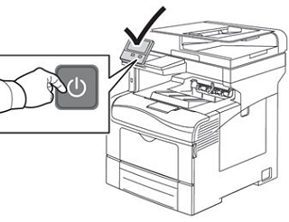
- At the printer control panel, press the Power/Wake button.
- To power off the printer, touch Power Off.
- If the printer does not respond to a single press of the Power/Wake button, then press and hold the button for 5 seconds. A Please Wait message appears as the printer powers down. After 10 seconds, the touch screen goes dark and the Power/Wake button flashes until the printer powers down.
- To power on the printer, press the Power/Wake button.

- Try your job again. If the problem persists, contact Support for additional assistance.
Return to Top
Xerox Versalink C405 – Error Code – 071-101
Recently we received a question on our online chat that was from a user receiving Error Code 071-101 on there Versalink C405. This individual was not an active customer – just someone needing help.
This is what we sent them-
071-101
Description
Tray 1 Miss Feed Jam/ Option Regi On Jam After a paper was fed from Tray 1, it did not reach the Registration Sensor.
Causes
• Turn Roller Assembly, PL 2.2.1 • Feed Roller Clutch, PL 2.2.8 • Tray 1 Feed Roller Kit, PL 2.2.99 • Registration Sensor, PL 5.1.3 • Bypass Tray Turn Roller, PL 5.1.8 • Turn Roller Clutch, PL 5.1.9 • Paper Handling Motor (P/H Drive Assembly), PL 11.1.19 • MCU PWB, PL 12.1.15 • Paper Jam Sensor, PL 15.2.3 • Feeder PWB, PL 15.2.3
Remedy
1. Check the installation of Tray 1. Is Tray 1 installed properly?
Go to step 2.
Reinstall Tray 1. 2. Check the paper transport path. Is there any debris found on the paper transport path? Remove the debris from the paper transport path. Go to step 3. 3. Check the installation of the Feed Rollers. Are the Feed Rollers installed properly? Go to step 4. Reinstall the Feed Rollers. 4. Check the Feed Rollers. Are the Feed Rollers deformed or worn out? Replace the Feed Rollers. Go to step 5. 5. Check the Registration Sensor operation. Perform DC330 Component Control [071-102] to check the operation of the Registration Sensor. Is the Registration Sensor operating normally? Go to step 6. Go to Registration Sensor. 6. Check the Turn Roller Clutch operation. Perform DC330 Component Control [071-016] to check the operation of the Turn Roller Clutch. Is the Turn Roller Clutch operating properly? Go to step 7. Go to Turn Roller Clutch. 7. Check the Feed Roller Clutch operation. Perform DC330 Component Control [071-015] to check the operation of the Feed Roller Clutch. Is the Feed Roller Clutch operating properly? Go to step 8. Go to Feed Roller Clutch. 8. Check the Paper Handling (P/H) Motor operation. Perform DC330 Component Control [071-009] to check the operation of the P/H Motor. Is the P/H Motor operating normally? • When the Optional Tray is not installed, replace the MCU PWB. • When the Optional Tray is installed, go to step 9. Go to Paper Handling Motor. 9. Check the Paper Jam Sensor operation (Tray 2). Perform DC330 Component Control [071-125] to check the operation of the Paper Jam Sensor. Is the Paper Jam Sensor operating normally? Replace the MCU PWB. Go to Paper Jam Sensor.
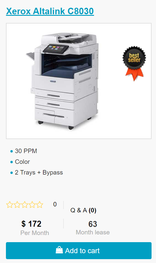
Looking for a new Xerox? Click the picture below for ordering!
We have C8030/35/45/55/70 available for delivery. Contact us or click the picture below.
ABOUT USA Copier Lease
USA Copier Lease is an exclusive Xerox dealer and our clients are across the United States.
We can service and support your Xerox devices anywhere in the United States with a guaranteed same day / next day on-site service guarantee.
In addition, to learn more about how USA Copier Lease can help your organization assess your existing copier leases or provide a quote for new copier, call (800) 893 1183 or send an email to online@usamagnum.com
If you have read this far and are an IT organization looking for a Xerox Partner to pass referrals to, Contact us. We provide great incentives for copier referrals past.
Во время работы с аппаратом могут возникать проблемы, связанные с неисправностями «железа» или ПО. И если расходные материалы можно просто заменить, то с «мозгами» нужно разбираться. Поэтому, для экономии времени и удобства, ниже представлены возможные коды ошибок (FAULT ERROR CODE), которые показывают Xerox DocuColor DC 240/250/242/252/260 и WorkCentre WC 7655/7665/7675/7755/7765/7775 при неисправности, и их значение:
коды ошибок (fault code/error) продолжение. Часть 2
…
061-323 ERROR — RAP No SOS Failure.
061-324 ERROR — RAP No SOS Failure.
061-325 ERROR — RAP No SOS Failure.
061-326 ERROR — RAP ROS Connect Failure Yellow.
061-327 ERROR — RAP ROS Connect Failure.
061-328 ERROR — RAP ROS Connect Failure.
061-329 ERROR — RAP ROS Connect Failure Black.
061-334 ERROR — RAP ROS Y/M VDD Failure.
061-335 ERROR — RAP ROS C/K VDD Failure.
061-336 ERROR — RAP ROS Y/M VDD Down Failure.
061-337 ERROR — RAP ROS C/K VDD Down Failure.
061-338 ERROR — RAP SOS Stop Magenta Failure.
061-339 ERROR — RAP SOS Stop Black Failure.
061-340 ERROR — RAP ROS LD Failure Black.
061-341 ERROR — RAP ROS LD Failure Yellow.
061-342 ERROR — RAP ROS LD Failure Magenta.
061-343 ERROR — RAP ROS LD Failure Cyan.
061-600 ERROR — RAP ROS Data Failure Yellow.
061-601 ERROR — RAP ROS Data Failure Magenta.
061-602 ERROR — RAP ROS Data Failure Cyan.
061-603 ERROR — RAP ROS Data Failure Black.
061-604 ERROR — RAP LD Alarm Yellow.
061-605 ERROR — RAP LD Alarm Magenta.
061-606 ERROR — RAP LD Alarm Cyan.
061-607 ERROR — RAP LD Alarm Black.
062-210 ERROR — RAP IISS Hot Line Failure.
062-211 ERROR — RAP IIT/IPS EEPROM Failure (IPS).
062-220 ERROR — RAP IPS-EXT Connection Failure.
062-277 ERROR — RAP IIT/IPS-DADF Communication Failure.
062-278 ERROR — RAP IIT-Extension Communication Failure.
062-300 ERROR — RAP Platen Interlock Open.
062-310 ERROR — RAP IIT/IPS-ESS Communication Failure.
062-311 ERROR — RAP IIT Software Logic Failure.
062-321 ERROR — RAP IPS-YATA Connection Failure.
062-322 ERROR — RAP EXT-YATA Connection Failure.
062-323 ERROR — RAP YATA PWBA Failure.
062-345 ERROR — RAP IIT/IPS EEPROM Failure (IIT).
062-355 ERROR — RAP IPS Fan Failure.
062-356 ERROR — RAP Lamp Fan Failure.
062-357 ERROR — RAP CCD Fan Failure. An error signal was detected for the CCD fan.
062-360 ERROR — RAP Carriage Position Failure.
062-362 ERROR — RAP X Hard Failure.
062-371 ERROR — RAP Lamp Failure.
062-380 ERROR — RAP Platen AOC Failure.
062-386 ERROR — RAP Platen AOC Failure.
062-389 ERROR — RAP Carriage Over Run (Scan End).
062-392 ERROR — RAP IT/IPS Memory Failure.
062-393 ERROR — RAP IIT/IPS PWB Failure.
062-790 ERROR — RAP X Detect Failure.
063-210 ERROR — RAP Extension EEPROM Failure.
063-220 ERROR — RAP IPS-EXT Psync Failure.
063-230 ERROR — RAP EXT Image Parameter Failure.
063-240 ERROR — RAP EXT Image Parameter Failure.
065-210 ERROR — RAP Extension Page Memory Failure 1.
065-211 ERROR — RAP CIS Shading FROM Failure
065-212 ERROR — RAP CIS Shading Level Failure.
065-213 ERROR — RAP CIS Output Level Failure.
065-215 ERROR — RAP Extension Page Memory Failure 2.
065-216 ERROR — RAP Extension Page Memory Failure 3.
065-219 ERROR — RAP CIS Black White Level Failure.
065-220 ERROR — RAP 1P DUP PWB-EXT Psync Failure.
071-101 ERROR — RAP Feed Out Sensor 1 is not turned ON.
071-104 ERROR — RAP Pre Registration Sensor ON Jam (Tray 1).
071-105 ERROR — RAP Registration Sensor ON Jam (Tray 1).
071-210 ERROR — RAP Tray 1 Lift Up Failure.
072-101 ERROR — RAP Tray 2 Miss Feed Jam.
072-102 ERROR — RAP The Tray 1 Feed Out Sensor does not turn ON.
072-104 ERROR — RAP Pre-Registration Sensor ON Jam (Tray 2).
072-105 ERROR — RAP Registration Sensor ON Jam (Tray 2).
072-210 ERROR — RAP Tray 2 Lift Up Failure.
073-101 ERROR — RAP Tray 3 Miss Feed Jam.
073-102 ERROR — RAP Feed Out Sensor 1 ON Jam (Tray 3).
073-104 ERROR — RAP Pre Registration Sensor ON Jam (Tray 3).
073-105 ERROR — RAP Registration Sensor ON Jam (Tray 3).
073-210 ERROR — RAP Tray 3 Lift Up Failure.
074-101 ERROR — RAP Pre Feed Sensor 4 is not ON within the specified time after the start of feed from Tray 4.
074-102 ERROR — RAP Feed Out Sensor 1 ON Jam (Tray 4).
074-103 ERROR — RAP The Tray 4 Feed Out Sensor is not ON within the specified time for paper fed from Tray 4.
074-104 ERROR — RAP Pre Registration Sensor ON Jam (Tray 4).
074-105 ERROR — RAP Registration Sensor ON Jam (Tray 4).
074-210 ERROR — RAP Tray 4 Lift Up Failure.
075-100 ERROR — RAP Tray 5/Bypass Pre Feed Sensor is not ON within the specified time after the start of feed from Tray 5.
075-101 ERROR — RAP Tray 5/Bypass Feed Out Sensor is not ON within the specified time for paper fed from Tray 5.
075-109 ERROR — RAP Paper from Tray 5/Bypass does not turn ON Pre Regi Sensor within a specified time.
075-135 ERROR — RAP Paper from Tray 5/Bypass does not turn ON Regi Sensor within a specified time.
075-210 ERROR — RAP Tray 5/Bypass Lift Up Sensor does not turn ON within a specified time after Tray 5 begins to lift.
075-211 ERROR — RAP Tray 5/Bypass Lift Down Sensor does not turn ON within a specified time after Tray 5 begins to lower.
077-102 ERROR — RAP Paper from Tray 2 did not turn on the Transport Path Sensor 1 within the specified time.
077-103 ERROR — RAP The Fuser Exit Sensor did not turn off within the specified time in straight exit mode.
077-106 ERROR — RAP The Fuser Exit Sensor did not come on within the specified time after the Registration Motor.
077-107 ERROR — RAP The Fuser Exit Sensor did not turn off within the specified time in invert exit mode.
077-109 ERROR — RAP The IOT Exit Sensor did not come on at the specified time in non-invert mode.
077-111 ERROR — RAP The IOT Exit Sensor did not come on within the specified time in invert exit mode.
077-113 ERROR — RAP The IOT Exit Sensor did not turn off at the specified time in non-invert mode.
077-115 ERROR — RAP The IOT Exit Sensor did not turn off within the specified time in invert exit mode.
077-118 ERROR — RAP Paper from Duplex did not turn on the Pre Regi Sensor within the specified time.
077-120 ERROR — RAP Post 2nd BTR Sensor On JAM.
077-123 ERROR — RAP Duplex In Sensor does not turn ON a spec time after the start of invert.
077-129 ERROR — RAP Paper from Duplex did not turn on the Regi Sensor within the specified time.
077-130 ERROR — RAP Duplex Out Sensor does not turn ON witin a specified time after Duplex In Sensor turns ON.
077-300 ERROR — RAP The Front Cover is open.
077-301 ERROR — RAP The Left Hand Interlock is open.
077-302 ERROR — RAP The Right Hand Cover Interlock is open.
077-303 ERROR — RAP PH Drawer Interlock Open.
077-304 ERROR — RAP The Tray 5/Bypass Cover Interlock is open.
077-312 ERROR — RAP Feeder Communication Failure.
077-909 ERROR — RAP One of the IOT sensors detected paper when power was turned on or when an interlock was closed.
077-967 ERROR — RAP The specified paper type and the paper type being used are different.
077-968 ERROR — RAP The type of paper in the tray was changed.
078-100 ERROR — RAP Paper from Tray 6 does not turn ON Pre Regi Sensor within a specified time.
078-101 ERROR — RAP The Tray 6 Feed Out sensor is not ON within the specified time for paper fed from Tray 6.
078-102 ERROR — RAP Paper from Tray 6 does not turn ON the Regi Sensor within a specified time.
078-151 ERROR — RAP The Tray 6 Feed Out Sensor did not come on within the specified time after the start of feed.
078-250 ERROR — RAP HCF Tray #2 Lift Up Fail.
078-300 ERROR — RAP The HCF transport interlock is open.
078-301 ERROR — RAP HCF Side Out Interlock Open.
089-600 ERROR — RAP Incorrect Fast Scan positioning for the reference color Cyan was detected during fine adjustment.
089-601 ERROR — RAP The Inner MOB Sensor failed to detect the fine-adjustment patterns properly during fine adjustment.
089-602 ERROR — RAP The CENTER MOB Sensor failed to detect the fine-adjustment patterns properly during fine adjustment.
089-603 ERROR — RAP The OUTER MOB Sensor failed to detect the fine-adjustment patterns properly during fine adjustment.
089-604 ERROR — RAP The INNER MOB Sensor failed to detect the rough-adjustment patterns properly during Yellow rough adjustment.
089-605 ERROR — RAP The CENTER MOB Sensor failed to detect the rough-adjustment patterns properly during Yellow rough adjustment.
089-606 ERROR — RAP The OUTER MOB Sensor failed to detect the rough-adjustment patterns properly during Yellow rough adjustment.
089-607 ERROR — RAP The INNER MOB Sensor failed to detect the rough-adjustment patterns correctly during Magenta rough adjustment.
089-608 ERROR — RAP The CENTER MOB Sensor failed to detect the rough-adjustment patterns properly during Magenta rough adjustment.
089-609 ERROR — RAP The OUTER MOB Sensor failed to detect the rough-adjustment patterns properly during Magenta rough adjustment.
089-610 ERROR — RAP The INNER MOB Sensor failed to detect the rough-adjustment patterns properly during Cyan rough adjustment.
089-611 ERROR — RAP The CENTER MOB Sensor failed to detect the rough-adjustment patterns properly during Cyan rough adjustment.
089-612 ERROR — RAP The MOB Sensor OUT failed to detect the rough-adjustment patterns properly during Cyan rough adjustment.
089-613 ERROR — RAP The INNER MOB Sensor failed to detect the rough-adjustment patterns properly during Black rough adjustment.
089-614 ERROR — RAP The CENTER MOB Sensor failed to detect the rough-adjustment patterns properly during Black rough adjustment.
089-615 ERROR — RAP The MOB Sensor OUT failed to detect the rough-adjustment patterns properly during Black rough adjustment.
089-616 ERROR — RAP RC Data OverFlow Failure.
089-617 ERROR — RAP RC Data OverRange Failure.
091-311 ERROR — RAP The voltage level of the CC cleaner position sensor did not change within the specified time.
091-312 ERROR — RAP Charge (K) Preclean HVPS has failed.
091-313 ERROR — RAP DRUM CRUM ASIC Communication Failure.
091-320 ERROR — RAP Charge Corotron Wire is broken.
091-400 ERROR — RAP The replacement date for Waste Toner Bottle (regular) is near.
091-401 ERROR — RAP The black drum cartridge is near the end-of-life.
091-403 ERROR — RAP The CC Assembly is near the end-of-life.
091-404 ERROR — RAP The CC Assembly has reached the end-of-life.
091-411 ERROR — RAP The yellow drum cartridge is near the end-of-life.
091-421 ERROR — RAP The magenta drum cartridge is near the end-of-life.
091-431 ERROR — RAP The cyan drum cartridge is near the end-of-life.
091-910 ERROR — RAP The waste toner bottle is not present.
091-911 ERROR — RAP The waste toner bottle is full.
091-913 ERROR — RAP The black drum cartridge (K) has reached the end-of-life.
091-914 ERROR — RAP Communication failure between the MCU and the black Drum CRUM.
091-915 ERROR — RAP The MCU detected incorrect data in the black drum cartridge CRUM.
091-916 ERROR — RAP The CRUM authentication registration data on the drum cartridge is incorrect.
091-917 ERROR — RAP MCU cannot communicate with the CRUM in drum Y.
091-918 ERROR — RAP Communication failure with the magenta Drum CRUM.
091-919 ERROR — RAP Communication failure with the cyan Drum CRUM.
091-920 ERROR — RAP The MCU detected incorrect data in the Yellow drum cartridge CRUM.
091-921 ERROR — RAP Drum CRUM is disconnected.
091-922 ERROR — RAP Wrong Data in magenta drum cartridge.
091-923 ERROR — RAP Wrong data in cyan drum cartridge.
091-924 ERROR — RAP The CRUM authentication registration data on the yellow drum cartridge is incorrect.
091-925 ERROR — RAP Wrong data in yellow Magenta cartridge.
091-926 ERROR — RAP The CRUM authentication registration data on the cyan drum cartridge is incorrect.
091-927 ERROR — RAP Yellow Drum CRUM is disconnected.
091-928 ERROR — RAP Magenta Drum CRUM is disconnected.
091-929 ERROR — RAP Cyan Drum CRUM is disconnected.
091-932 ERROR — RAP The yellow drum cartridge (Y) has reached the end-of-life.
091-933 ERROR — RAP The magenta drum cartridge (M) has reached the end-of-life.
091-934 ERROR — RAP The cyan drum cartridge (C) has reached the end-of-life.
092-649 ERROR — RAP The MOB ADC Shutter remains open due to shutter failure.
092-650 ERROR — RAP The MOB ADC Shutter remains closed due to shutter failure.
092-651 ERROR — RAP The output read by ADC Sensor from the clean Photoreceptor surface is out of range.
092-652 ERROR — RAP The measured ADC Patch density is light. (Over 75% of Vclean).
092-653 ERROR — RAP ATC SNR-Yellow output signal failure.
092-654 ERROR — RAP ATC SNR-Magenta output signal failure.
092-655 ERROR — RAP ATC SNR-Cyan output signal failure.
092-656 ERROR — RAP ATC SNR-black output signal failure.
092-657 ERROR — RAP The amplitude of ATC Yellow Sensor output is out of range.
092-658 ERROR — RAP The amplitude of ATC Magenta Sensor output is out of range.
092-659 ERROR — RAP The amplitude of ATC Cyan Sensor output is out of range.
092-660 ERROR — RAP The amplitude of ATC Black Sensor output is out of range.
092-661 ERROR — RAP The temperature output of the environment sensor is out of range.
092-662 ERROR — RAP The humidity output of the environment sensor is out of range.
092-663 ERROR — RAP The two levels of ADC Patch density created in Mini-Setup are reversed.
093-300 ERROR — RAP Marking Drawer Interlock Open.
093-313 ERROR — RAP The Low Toner Sensor failed to detect any toner after the Toner Cartridge Motor was energized.
093-314 ERROR — RAP Yellow Dispense failure.
093-315 ERROR — RAP Magenta Dispense failure.
093-316 ERROR — RAP Cyan Dispense failure.
093-317 ERROR — RAP Black Dispense failure.
093-320 ERROR — RAP There was a problem with the developer motor rotation.
093-421 ERROR — RAP The Black Toner Cartridge (K1) is empty and the Black Toner Cartridge (K2) is near empty.
093-422 ERROR — RAP The Black Toner Cartridge (K2) is empty and the Black Toner Cartridge (K1) is near empty.
093-423 ERROR — RAP Yellow toner is near empty.
093-424 ERROR — RAP Magenta toner is near empty.
093-425 ERROR — RAP Cyan toner empty.
093-600 ERROR — RAP Yellow Dispense near failure.
093-601 ERROR — RAP Magenta Dispense near failure.
093-602 ERROR — RAP Cyan Dispense near failure.
093-603 ERROR — RAP Black Dispense near failure.
093-912 ERROR — RAP The Black Dispense Motor rotation timed out indicating that the Black Cartridge and Reserve Tank are empty.
093-918 ERROR — RAP A communication failure with Black Toner Cartridge CRUM K2.
093-924 ERROR — RAP A communication failure with Black Toner Cartridge CRUM K1.
093-925 ERROR — RAP The data written to the toner CRUM K1 did not agree with the data read.
093-926 ERROR — RAP Toner Cartridge CRUM K1 Authentication Data is different.
093-927 ERROR — RAP A communication failure with Yellow Toner Cartridge CRUM Y.
093-928 ERROR — RAP A communication failure with Magenta Toner Cartridge CRUM M.
093-929 ERROR — RAP A communication failure with Cyan Toner Cartridge CRUM C.
093-932 ERROR — RAP Cartridge Exchange Time Over.
093-934 ERROR — RAP The data written to the toner CRUM M did not agree with the data read.
093-935 ERROR — RAP The data written to the toner CRUM C did not agree with the data read.
093-936 ERROR — RAP The data written to the toner CRUM K2 did not agree with the data read.
093-937 ERROR — RAP Toner Cartridge CRUM Y Authentication Data is different.
093-938 ERROR — RAP Toner Cartridge CRUM M Authentication Data is different.
093-939 ERROR — RAP Toner Cartridge CRUM C Authentication Data is different.
093-940 ERROR — RAP Toner Cartridge CRUM K2 Authentication Data is different.
094-320 ERROR — RAP Retraction was not detected within the specified time after retraction of the 1st BTR started.
094-321 ERROR — RAP First BTR Contact Failure.
094-322 ERROR — RAP Second BTR Retract Failure.
094-323 ERROR — RAP Contact was not detected within the specified time after contact with the 2nd BTR started.
102-356 ERROR — RAP Fatal error related to the EWS.
102-380 ERROR — RAP Fatal error in the MF UI count.
102-381 ERROR — RAP ESS error during communication between ESS and the control panel.
102-382 ERROR — RAP A verification message was not returned from the Control Panel within the specified time.
112-700 ERROR — RAP The punch dust box is full.
116-210 ERROR — RAP Media Reader Fatal Error.
116-211 ERROR — RAP Media Reader Cable disconnected.
116-212 ERROR — RAP [Media Reader] MediaLib SW Logic Failure.
116-310 ERROR — RAP An error was detected while checking ESS font ROM DIMM #1.
116-312 ERROR — RAP An error was detected in the HDD encryption key during activation.
116-313 ERROR — RAP An encryption key was specified but the HDD itself was not encrypted.
116-314 ERROR — RAP An ethernet error was detected.
116-315 ERROR — RAP An error was detected during System Memory 1 R/W.
116-316 ERROR — RAP An error was detected during System Memory 2 R/W.
116-317 ERROR — RAP An error was detected when checking the MF ROM.
116-318 ERROR — RAP An error was detected when checking the expansion ROM R2.
116-321 ERROR — RAP System Software Fatal Error.
116-322 ERROR — RAP WebDAV S/W Failure.
116-323 ERROR — RAP An error was detected during the ESS PWB NVM Read/Write Check.
116-324 ERROR — RAP A fatal software exception error has occurred in the Controller PWB CPU.
116-325 ERROR — RAP An error occurred in ESS fan rotation.
116-329 ERROR — RAP A system call error related to the serial I/F was detected.
116-330 ERROR — RAP Error during HDD check.
116-331 ERROR — RAP An error related to the log was detected.
116-332 ERROR — RAP An error in the MF ROM ( ) was detected.
116-333 ERROR — RAP A problem occurred during software processing, and processing could no longer continue.
116-336 ERROR — RAP Redirector HD Failure. A problem was detected during HD access.
116-337 ERROR — RAP Fatal error with SNTP in general.
116-338 ERROR — RAP Fatal error with JBA in general.
116-340 ERROR — RAP There was insufficient page memory, input buffers, or work area.
116-341 ERROR — RAP Incorrect version or invalid combination ROM DIMMs are installed.
116-342 ERROR — RAP Fatal error related to the SNMP agent.
116-343 ERROR — RAP An IC error within the ESS PWB was detected.
116-346 ERROR — RAP Formatter failure. Error return from a system call.
116-348 ERROR — RAP Redirector failure. Error return from a system call.
116-349 ERROR — RAP There was an error with a call within SIF related to Pflite.
116-350 ERROR — RAP Fatal error with AppleTalk in general.
116-351 ERROR — RAP Fatal error related to EtherTalk.
116-352 ERROR — RAP Fatal error related to NetWare.
116-353 ERROR — RAP A physical problem was detected with the HDD during activation, causing the HDD not to activate.
116-354 ERROR — RAP A problem with the HDD product code was detected during activation.
116-355 ERROR — RAP Fatal error related to the SNMP agent.
116-356 ERROR — RAP The HDD was formatted, but an HDD failure occurred.
116-357 ERROR — RAP PostScript fatal system error.
116-358 ERROR — RAP Fatal error related to the salutation.
116-359 ERROR — RAP Fatal error in PLW.
116-360 ERROR — RAP Fatal error related to SMB.
116-361 ERROR — RAP SPL HDD fatal error. SpoolCont detected an error during HDD access.
116-362 ERROR — RAP SSDP software failure.
116-363 ERROR — RAP BMLinkS or print service software failure.
116-364 ERROR — RAP A timer error was detected.
116-365 ERROR — RAP SPL fatal error.
116-366 ERROR — RAP Report generator incorrect operation.
116-367 ERROR — RAP Parallel fatal error.
116-368 ERROR — RAP DumpPrint fatal error.
116-370 ERROR — RAP XJCL fatal error.
116-371 ERROR — RAP PCL Decomposer Software Failure. PCL fatal error.
116-373 ERROR — RAP Fatal error related to Dynamic DNS.
116-374 ERROR — RAP AutoSW fatal error.
116-376 ERROR — RAP Port 9100 Software Fail.
116-378 ERROR — RAP Fatal error related to MCR.
116-379 ERROR — RAP Fatal error related to MCC.
116-380 ERROR — RAP An error was detected while checking ESS font ROM DIMM #1.
116-381 ERROR — RAP The ABL did not agree with the ABL version information in NVM, or the data was corrupted.
116-382 ERROR — RAP An ABL access to NVM or HDD failed.
116-385 ERROR — RAP Fatal error related to the IDC.
116-388 ERROR — RAP It was detected that no HD is installed.
116-389 ERROR — RAP The system detected that no additional RAM was installed.
116-390 ERROR — RAP A version mismatch was detected between the standard ROM and NVM.
116-391 ERROR — RAP Incorrect specification of the country code, territory code, or paper size group.
116-395 ERROR — RAP Fatal error related to the USB.
116-701 ERROR — RAP Duplex printing is not possible due to insufficient memory.
116-702 ERROR — RAP Printing occurred with a substitute font.
116-703 ERROR — RAP PostScript data problem during PostScript grammar interpretation or language interpretation.
116-704 ERROR — RAP MediaReader No Insert (No Job).
116-705 ERROR — RAP MediaReader Format Error (No Job).
116-706 ERROR — RAP MediaReader: File Attribute Read Error (No Job).
116-707 ERROR — RAP MediaReader: Image File Read Error (No Job).
116-708 ERROR — RAP MediaReader: File Attribute Read Error (In Job).
116-709 ERROR — RAP MediaReader: Image File Read Error (Occurs during job).
116-710 ERROR — RAP Original size not correctly determined.
116-711 ERROR — RAP Mismatch in size and direction or ART EX form with paper to be printed.
116-712 ERROR — RAP PLW form / logo data cannot be registered due to insufficient RAM or HD space.
116-713 ERROR — RAP The job was divided because the HDD was full.
116-714 ERROR — RAP An HP-GL/2 (option) command error occurred.
116-715 ERROR — RAP The form could not be registered because the ART EX form registration upper limit was reached.
116-716 ERROR — RAP MediaReader File Does Not Exist.
116-717 ERROR — RAP MediaLib: Not Execute of New Request.
116-718 ERROR — RAP The specified ART EX form has not been registered.
116-720 ERROR — RAP PCL Memory Low, Page Simplified.
116-737 ERROR — RAP User defined data could not be registered because there was insufficient ART IV user definition memory.
116-738 ERROR — RAP Synthesis problem due to the specified ART IV form size and direction were different from the paper size and direction.
116-739 ERROR — RAP Form / logo data could not be registered because there was insufficient ART IV memory or HDD capacity.
116-740 ERROR — RAP An error occurred because the print data exceeded the printer limit.
116-741 ERROR — RAP No more forms can be registered because the number of ART IV Forms registered has reached the upper limit.
116-742 ERROR — RAP No more logo data can be registered because the number of ART IV log data registered has reached the upper limit.
116-743 ERROR — RAP The form or logo data could not be registered due to insufficient ART IV memory.
116-745 ERROR — RAP An ART IV command error occurred.
116-746 ERROR — RAP The specified form has not been registered.
116-747 ERROR — RAP The paper margin value is too large for the HP-GL/2 (option) effective coordinate area.
116-748 ERROR — RAP The HP-GL/2 (option) print data does not contain any image data.
116-749 ERROR — RAP The specified PostScript font is not in ROM or HDD.
116-771 ERROR — RAP Invalid JBIG Parameter DL Fixed.
116-772 ERROR — RAP Invalid JBIG Parameter D Fixed.
116-773 ERROR — RAP Invalid JBIG Parameter P Fixed.
116-774 ERROR — RAP Invalid JBIG Parameter YD Fixed.
116-775 ERROR — RAP Invalid JBIG Parameter LO Fixed.
116-776 ERROR — RAP Invalid JBIG Parameter MX Fixed.
116-777 ERROR — RAP Invalid JBIG Parameter MY Fixed.
116-778 ERROR — RAP Invalid JBIG Parameter VLENGTH Fixed.
116-780 ERROR — RAP There was a problem with the document attached to the received mail.
116-790 ERROR — RAP Stapling was cancelled.
123-200 ERROR — RAP The data received from ESS exceeded the buffer size of the storage destination within the control panel.
123-201 ERROR — RAP Data intended to be received from the control panel exceeded the buffer size of the storage destination within the control panel.
123-202 ERROR — RAP Events occurred that exceeded the processing capability for requests generated within the control panel.
123-203 ERROR — RAP UI Debug code.
123-204 ERROR — RAP SIO Parameter Failure (UI-Control panel).
123-205 ERROR — RAP SIO Command Failure (UI-Control panel).
123-206 ERROR — RAP SIO Status Failure (UI-Control panel).
123-207 ERROR — RAP Comm Manager Target Failure (UI-Control panel).
123-208 ERROR — RAP Comm Manager Command Failure (UI-Control panel).
123-209 ERROR — RAP EVM Returns Wrong Value (UI-Control panel).
123-310 ERROR — RAP Send Queue Full (UI-Control panel).
123-311 ERROR — RAP Receive Queue Full (UI-Control panel).
123-312 ERROR — RAP EVM Uses Wrong API (UI-Control panel).
123-313 ERROR — RAP AS Uses Wrong API (UI-Control panel).
123-314 ERROR — RAP Event-Waiting Timer Timeout (UI-Control panel).
123-315 ERROR — RAP CTS Internal Failure (UI-Control panel).
123-316 ERROR — RAP Send Request Queue Full SIO (UI-Control panel).
123-317 ERROR — RAP Receive Message Queue Full (UI-Control panel).
123-318 ERROR — RAP Receive Finish Queue Full (UI-Control panel).
123-319 ERROR — RAP Send Failure with No ACK (UI-Control panel).
123-320 ERROR — RAP Polling Failure (UI-Control panel).
123-321 ERROR — RAP Send Message Failure (UI-Control panel).
123-322 ERROR — RAP Target Failure (UI-Control panel).
123-323 ERROR — RAP Address Failure (UI-Control panel). Serial communication error.
123-324 ERROR — RAP Size Failure (UI-Control panel). Serial communication error.
123-325 ERROR — RAP Object Creation Failure (UI-Control panel).
123-326 ERROR — RAP Memory Overflow (UI-Control panel).
123-327 ERROR — RAP Button Overflow (UI-Control panel).
123-328 ERROR — RAP UI Internal Failure with Out of Area.
123-329 ERROR — RAP UI Internal Failure with Invalid Coordinates.
123-330 ERROR — RAP Interface Failure with Invalid Parameter LCD.
123-331 ERROR — RAP UI Internal Failure with Invalid LED Request.
123-332 ERROR — RAP I/F Failure (Invalid Parameter CP).
123-333 ERROR — RAP I/F Failure (No Communication).
123-334 ERROR — RAP I/F Failure (Receiving Error Key Code).
123-335 ERROR — RAP I/F Failure (Receiving Invalid Coordinates).
123-336 ERROR — RAP I/F Failure (DM-ACD Drv. I/F).
123-337 ERROR — RAP Frame Data Error with Invalid Data Type.
123-338 ERROR — RAP Frame Data Error Offset Address Out.
123-339 ERROR — RAP Display Request Code Invalid.
123-340 ERROR — RAP Interface Failure GUAM-DM I/F.
123-341 ERROR — RAP Event Queue Full (UI-Control panel).
123-342 ERROR — RAP Event Queue Empty (UI-Control panel).
123-343 ERROR — RAP Invalid Class (UI-Control panel).
123-344 ERROR — RAP Invalid Type (UI-Control panel).
123-345 ERROR — RAP Timer Queue Full (UI-Control panel).
123-346 ERROR — RAP Invalid Timer Number (UI-Control panel).
123-347 ERROR — RAP Undefined Trap (UI-Control panel).
123-348 ERROR — RAP Command Access Exception (UI-Control panel).
123-349 ERROR — RAP Invalid Command (UI-Control panel).
123-350 ERROR — RAP Privilege Command (UI-Control panel).
123-351 ERROR — RAP No FPU Exception (UI-Control panel).
123-352 ERROR — RAP Address Mis-align (UI-Control panel).
123-353 ERROR — RAP Data Access Exception (UI-Control panel).
123-354 ERROR — RAP Tag Overflow (UI-Control panel).
123-355 ERROR — RAP No Co Processor Exception (UI-Control panel).
123-356 ERROR — RAP Short of Area (UI-Control panel).
123-357 ERROR — RAP Cancel Wait Status (UI-Control panel).
123-358 ERROR — RAP Timeout (UI-Control panel).
123-359 ERROR — RAP Queue Overflow (UI-Control panel).
123-360 ERROR — RAP Context Failure (UI-Control panel).
123-361 ERROR — RAP Object Failure (UI-Control panel).
123-362 ERROR — RAP No Object (UI-Control panel).
123-363 ERROR — RAP Invalid ID (UI-Control panel).
123-364 ERROR — RAP Parameter Failure (UI-Control panel).
123-365 ERROR — RAP Reserve Attribute (UI-Control panel).
123-366 ERROR — RAP Reserve Function Code (UI-Control panel).
123-367 ERROR — RAP Unsupported Function (UI-Control panel).
123-368 ERROR — RAP Short of UI Memory (UI-Control panel).
123-369 ERROR — RAP Invalid Interface Value (UI-Control panel).
123-370 ERROR — RAP Interface Length Failure (UI-Control panel).
123-371 ERROR — RAP Interface Parameter Failure (UI-Control panel).
123-372 ERROR — RAP Interface Sequence Failure (UI-Control panel).
123-373 ERROR — RAP Channel Failure (UI-Control panel).
123-374 ERROR — RAP Invalid User Job ID (UI-Control panel).
123-375 ERROR — RAP Internal Resource Failure (UI-Control panel).
123-376 ERROR — RAP Internal Memory Failure (UI-Control panel).
123-377 ERROR — RAP UI Timer Failure (UI-Control panel).
123-378 ERROR — RAP Interface Format Failure (UI-Control panel).
123-379 ERROR — RAP Dispatch Failure (UI-Control panel).
123-380 ERROR — RAP Copy Interface Failure (UI-Control panel).
123-382 ERROR — RAP Scanner Interface Failure (UI-Control panel).
123-383 ERROR — RAP Report Interface Failure (UI-Control panel).
123-384 ERROR — RAP Server Access Failure (UI-Control panel).
123-385 ERROR — RAP Service Object Overflow (UI-Control panel).
123-386 ERROR — RAP Invalid Service Object (UI-Control panel).
123-387 ERROR — RAP Invalid Service Object Attribute (UI-Control panel).
123-388 ERROR — RAP Attribute Failure (UI-Control panel).
123-389 ERROR — RAP Argument Failure (UI-Control panel).
123-390 ERROR — RAP Job Parameter Failure (UI-Control panel).
123-391 ERROR — RAP Job Actual Parameter Failure (UI-Control panel).
123-392 ERROR — RAP Auditron Failure (UI-Control panel).
123-393 ERROR — RAP EP Failure (UI-Control panel).
123-394 ERROR — RAP File Access Failure (UI-Control panel).
123-395 ERROR — RAP NVM Failure (UI-Control panel).
123-396 ERROR — RAP FF Failure (UI-Control panel).
123-397 ERROR — RAP MGR Failure (UI-Control panel).
123-398 ERROR — RAP Delay Release Queue Full (UI-Control panel).
123-399 ERROR — RAP Internal Failure (UI-Control panel).
123-400 ERROR — RAP Internal Failure (UI-Control panel).
124-310 ERROR — RAP DC132 11 — The product number was not specified.
124-311 ERROR — RAP DC132 09 — The serial number registration field failed.
124-312 ERROR — RAP DC132 12 — Product numbers did not agree.
124-313 ERROR — RAP DC132 10 — Serial numbers did not agree.
124-314 ERROR — RAP DC 132-01 — IOT Speed Failure.
124-315 ERROR — RAP DC 132-02 — IOT Speed Mismatch.
124-316 ERROR — RAP DC 132-04 — Product a/f Model Failure.
124-317 ERROR — RAP DC 132-04 — Product a/f All Product Model Mismatch.
124-318 ERROR — RAP Product Type for S/W Key Failure.
124-319 ERROR — RAP DC 132-08 — All Product Type For S/W Key Mismatch.
124-320 ERROR — RAP EEP ROM Failure.
124-321 ERROR — RAP Backup SRAM Failure. An NVM ROM write problem occurred on the ESS PWB.
124-322 ERROR — RAP DC 132-05 — Copy/Scan/Print S/W Key by PWE Failure.
124-323 ERROR — RAP DC 132-06 — Copy/Scan/Print S/W Key 1 Failure.
124-324 ERROR — RAP All Billings Mismatch.
124-325 ERROR — RAP Billing Restoration Failure.
124-333 ERROR — RAP ASIC Failure (Panther).
124-334 ERROR — RAP Standard Font ROM Error.
124-335 ERROR — RAP Font ROM Not Found.
124-337 ERROR — RAP ESS Standard RAM Error.
124-338 ERROR — RAP Same Font ROMs Found.
124-339 ERROR — RAP ROM DIMM of another product found.
124-340 ERROR — RAP The three CRUM market destination values are not set up (0 or different).
124-341 ERROR — RAP One CRUM market destination value is different (IOT).
124-342 ERROR — RAP One CRUM market destination value is different (SYS 1).
124-343 ERROR — RAP One CRUM market destination value is different (SYS 2).
124-350 ERROR — RAP The three CRUM OEM destination values are not set up (0 or different).
124-351 ERROR — RAP One CRUM OEM destination value is different (IOT).
124-352 ERROR — RAP One CRUM OEM destination value is different (SYS 1).
124-353 ERROR — RAP One CRUM OEM destination value is different (SYS 2).
124-360 ERROR — RAP CRUM Valid/Invalid is not set up at the three locations (0 or different values).
124-361 ERROR — RAP CRUM Validation Failure MCU.
124-362 ERROR — RAP CRUM Validation Failure SYS 1.
124-363 ERROR — RAP CRUM Validation Failure SYS 2.
124-372 ERROR — RAP IOT sc Soft Failure.
124-373 ERROR — RAP IOT Manager SW Failure.
124-374 ERROR — RAP IOT IM Device Driver SW Failure.
124-380 ERROR — RAP CRUM Market fail ALL (2).
124-381 ERROR — RAP CRUM Market fail MCU (2).
124-382 ERROR — RAP CRUM Market fail SYS 1 (2).
124-383 ERROR — RAP CRUM Market fail SYS 2 (2).
124-390 ERROR — RAP CRUM OEM fail ALL (2).
124-391 ERROR — RAP CRUM OEM fail MCU (2).
124-392 ERROR — RAP CRUM OEM fail SYS 1 (2).
124-393 ERROR — RAP CRUM OEM fail SYS 2 (2).
124-701 ERROR — RAP Side Tray to Center Tray.
124-704 ERROR — RAP The output tray was changed from the Folder Tray to the Center Tray and printing continued.
124-705 ERROR — RAP Punching Cancelled.
124-706 ERROR — RAP Folding Cancelled.
124-708 ERROR — RAP The output tray has been changed to the Sub Tray because a failure was detected in the specified output tray.
124-709 ERROR — RAP Stapler Sheet Count is too high.
125-311 ERROR — RAP PSWcont Unexpected Failure.
127-210 ERROR — RAP DFE Communication Failure.
127-211 ERROR — RAP DFE Parameter Error.
127-212 ERROR — RAP ExtPrint Check Mode Error.
127-213 ERROR — RAP External Print IF Mismatch.
127-220 ERROR — RAP Communication Error (video) detected by the DFE.
127-221 ERROR — RAP Communication Error (Command) detected by the DFE.
127-310 ERROR — RAP ESR Task Fatal Error.
127-311 ERROR — RAP ExtPRT.
127-320 ERROR — RAP DFE Critical Failure.
127-337 ERROR — RAP Job Template HDD Write Error.
127-342 ERROR — RAP Job Template Monitor Failure.
127-353 ERROR — RAP LPD Soft Fatal Error.
127-354 ERROR — RAP FTP Server Software Failure.
127-396 ERROR — RAP Mail I/O Soft Fatal error.
127-398 ERROR — RAP IPP Soft Fatal Error.
127-399 ERROR — RAP JME Soft Fatal Error.
202-399 ERROR — RAP Timer Internal Fail.
You are here: Home / error code / Xerox Phaser 7100 error and solving error codes
– Compatible Printer model: Xerox Phaser 7100
– Xerox Phaser 7100 Error Codes with quick guides:
- Code: 010-105, 010-112
- Description: Fuser Unit Exit Sensor Jam The Fuser Unit has failed due to one of the following problems. • After a paper that had stopped at the Registration position was transported again, the paper did not reach the Fuser Exit Sensor within the specified time. • After the Fuser Exit Sensor has detected a paper, the paper passed by the Fuser Exit Sensor before the specified time. • 010-105: Fuser Unit Exit Sensor On Jam • 010-112: Fuser Unit Exit Out Early Jam
- Causes: • Fuser Motor (Fuser Drive Assembly), PL 4.2.16 • 2nd BTR (Transfer Roller), PL 4.3.18 • Registration Sensor, PL 5.1.3 • Registration Roller (Registration Chute Assembly), PL 5.1.1 • Registration Clutch, PL 5.1.11 • Exit Roller (Fuser Unit), PL 10.1.1 • Fuser Exit Sensor (Fuser Unit), PL 10.1.1 • Paper Handling Motor (Paper Handling Drive Assembly, PL 11.1.19 • MCU PWB, PL 12.1.15
- Troubleshooting Guides: 1. Check the paper transport path Is there any debris on the paper transport path? Remove the debris. Go to step 2. 2. Check the installation of the Registration Roller (Registration Chute). Is the Registration Chute installed properly? Go to step 3. Reinstall the Registration Chute. 3. Check the Registration Roller (Registration Chute). Is the Registration Chute damaged? Replace the Registration Chute. Go to step 4. 4. Check the Registration Sensor operation. Perform DC330 Component Control [071-102] to check the operation of the Registration Sensor. Is the Registration Sensor operating properly? Go to step 5. Go to Sensor Troubleshooting. 5. Check the Registration Clutch operation. Perform DC330 Component Control [071-013] to check the operation of the Registration Clutch. Is the Registration Clutch operating properly? Go to step 6. Go to Registration Clutch. 6. Check the Paper Handling (P/H) Motor operation. Perform DC330 Component Control [071-009] to check the operation of the P/H Motor. Is the P/H Motor operating properly? Go to step 7. Go to Paper Handling Motor. 7. Check the Fuser Exit Sensor operation. Perform DC330 Component Control [071-104] to check the operation of the Fuser Exit Sensor. Is the Fuser Exit Sensor operating properly? Go to step 8. Go to Fuser Exit Sensor. 8. Check the Fuser Motor operation. Perform DC330 Component Control [010-001] to check the operation of the Fuser Motor. Is the Fuser Motor operating properly? Replace the MCU PWB. Go to Fuser Motor.
- Code: 010-106
- Description: Exit Off Jam After a paper has passed by the Registration Sensor, the paper did not pass by the Fuser Exit Sensor within the specified time.
- Causes: • Fuser Motor (Fuser Drive Assembly), PL 4.2.16 • Fuser Exit Sensor (Fuser Unit), PL 10.1.1 • Exit Roller (Fuser Unit), PL 10.1.1 • MCU PWB, PL 12.1.15
- Troubleshooting Guides: 1. Check the paper transport path Is there any debris on the paper transport path? Remove the debris. Go to step 2. 2. Check the Fuser Unit. Is the Fuser Unit damaged? Go to step 3. Reinstall the Fuser Unit. 3. Check the Fuser Exit Sensor operation. Perform DC330 Component Control [071-104] to check the operation of the Fuser Exit Sensor. Is the Fuser Exit Sensor operating properly? Go to step 4. Go to Fuser Exit Sensor. 4. Check the Fuser Motor operation. Perform DC330 Component Control [010-001] to check the operation of the Fuser Motor. Is the Fuser Motor operating properly? Replace the MCU PWB. Go to Fuser Motor.
- Code: 010-311 … 010-355
- Description: • 010-311: Fuser Unit Heat Roll STS-1 Disconnection Fail • 010-319: Fuser Unit NC Sensor Differential Amp Fail • 010-328: Fuser Unit Warm Up Time Fail (Not Ready) • 010-331: Heat Roll STS Over Temperature Fail • 010-332: Heat Roll NC Sensor Disconnection Fail • 010-333: Heat Roll NC Sensor Over Temperature Fail • 010-334: Heat Roll NC Sensor Broken Fail • 010-335: Heat Roll NC Sensor Range Fail • 010-338: Fuser Unit On Time Fail • 010-339: Heat Roll NC Sensor Low Temperature Fail • 010-340: Fuser Unit Detached • 010-344: Heat Roll STS Sensor Low Temperature Fail • 010-345: Fuser Unit Hard Relay Off Fail • 010-346: Fuser Main Lamp Data Renewal Fail • 010-347: Fuser Sub Lamp Data Renewal Fail • 010-355: Fuser Cool Down Timeout Fail.
Fuser Unit Fail The Fuser Unit has failed due to one of the following problems. • A differential circuit output error was detected between the detection output and the compensation output of the Fuser Unit NC Sensor. • When the Lamp On time meets the following conditions, where Tws °C is the temperature at the Wait state start time that is obtained at the NCSCenter. • The temperature monitor AD value of the STS-Front was detected to be higher than T[HITMP (2)] 3 times in a row. • During Warm Up Control, an abnormal detected temperature due to NC Sensor malfunction or poor contact was detected. • The Fuser Unit Main Lamp or Sub Lamp has been On continuously for longer than the setting time (NVM). • At the first Lamp Off after it was turned On, the NC temperature is continuously at EP_U4_LOW_NC °C or lower 8 or more times in a row. • The Thermistor disconnection detected. • At the first Heater OFF after it was turned On, the detected temperature at the edge STS is continuously at EP_U4_LOW_STS °C or lower 8 or more times in a row. • Notified at the moment the Relay is cut off from the circuit. • The detected temperature at the NC or the STS has not changed during this period, although the Main Lamp has been On continuously for 15 s or longer. • The Cool Down Mode has continued for EP_U4_COOL_TIME * 10 s or longer. - Causes: • DRW Fuser Harness Assembly, PL 4.1.7 • Fuser Unit, PL 10.1.1 • MCU PWB, PL 12.1.15 • AC PWB Assembly, PL 12.1.16 • LVPS PWB, PL 12.2.1 • Option Harness Assembly, PL 12.3.5
- Troubleshooting Guides: 1. Check the installation of the Fuser Unit. Is the Drawer Connector between the Fuser Unit and Main Unit (P/J601) free of broken/bent pins, debris, burns, and etc., and the unit is installed properly? Go to step 2. Reinstall the Fuser Unit. 2. Check the connections between the Fuser Unit and MCU PWB, as well as between the Fuser Unit and AC PWB. Are the connectors P/J601, P/J459, and P/J503 connected securely? Go to step 3. Connect the connectors P/J601, P/J459, and P/J503. 3. Check the connection between the AC PWB and MCU PWB. Are the connectors P/J505 and P/J464 connected securely? Go to step 4. Connect the connectors P/J505 and P/J464. 4. Check the conductivity of the DRW Fuser Harness Assembly. Are the connections between P/J601<=> P/J459 and between P/J601 <=> P/J503 conducting properly? Go to step 5. Replace the DRW Fuser Harness Assembly. 5. Check the conductivity of the Option Harness Assembly. Is the connection between P/J505 <=> P/J464 conducting properly? Go to step 6. Replace the Option Harness Assembly. 6. Check the voltage supply (+5VDC) to the Fuser Unit. Measure the voltages between the MCU PWB GND <=> P/J459-5 and MCU PWB GND <=> P/J459-13. Is there a voltage (approx. +5VDC) output? Go to step 7. Go to +5VDC Power Troubleshooting. 7. Check the voltage supply (+3.3VDC) to the Fuser Unit. Measure the voltage between the MCU PWB GND <=> P/J459-1. Is there a voltage (approx. +3.3VDC) output? Go to step 8. Go to +3.3VDC Power Troubleshooting. 8. Replace the Fuser Unit. Does the error persist? Go to step 9. Troubleshooting complete. 9. Replace the AC PWB. Does the error persist? Replace the MCU PWB. Troubleshooting complete.
- Code: 010-330
- Description: Fuser Motor Fail The Fuser Motor rotation failure was detected.
- Causes: • Front Harness Assembly, PL 4.2.11 • Fuser Motor (Fuser Drive Assembly), PL 4.2.16 • MCU PWB, PL 12.1.15 • LVPS PWB, PL 12.2.1 • Main Harness Assembly, PL 12.3.1
- Troubleshooting Guides: 1. Check the Fuser Motor operation. Perform DC330 Component Control [010-001] to check the operation of the Fuser Motor. Is the Fuser Motor operating properly? Replace the MCU PWB. Go to step 2. 2. Check the installation of the Fuser Motor. Manually rotate the Fuser Motor. Does the Motor rotate? Reinstall the Fuser Drive Assembly. Go to step 3. 3. Check the connections between the Fuser Motor and MCU PWB, as well as between the Fuser Motor and LVPS PWB. Are the connectors P/J475, P/J4751, P/J4755, P/J524, P/J2711, and P/J242 connected securely? Go to step 4. Connect the connectors P/J475, P/J4751, P/J4755, P/J524, P/J2711, and P/J242. 4. Check the conductivity between the Fuser Motor and Relay Connector. Are the connections between P/J4755 <=> P/J4751 and between P/J242 <=> P/J2711 conducting properly? Go to step 5. Replace the Front Harness Assembly. 5. Check the conductivity between the Relay Connector and LVPS PWB. Is the connection between P/J2711 <=> P/J524 conducting properly? Go to step 6. Replace the Main Harness Assembly. 6. Check the conductivity between the Relay Connector and MCU PWB. Is the connection between P/J4751 <=> P/J475 conducting properly? Go to step 7. Replace the Main Harness Assembly. 7. Check the voltage supply (+3.3VDC) to the Fuser Motor. Measure the voltage between the MCU PWB GND <=> P/J475-16. Is there a voltage (approx. +3.3VDC) output? Go to step 8. Go to +3.3VDC Power Troubleshooting. 8. Check the voltage supply (+24VDC) to the Fuser Motor. Measure the voltage between the LVPS PWB GND <=> P/J524-1. Is there a voltage (approx. +24VDC) output? Close the Interlock Switch and check. Replace the Fuser Drive Assembly. Replace the LVPS PWB.
- Code: 010-421, 010-906
- Description: Fuser Unit Error – Life End The print volume has reached the specified value (Max value), which indicates that further usage will damage the Fuser Unit. • 010-421: Fuser Unit Life End Quality (operation can still continue) (quality lifespan has ended) (ERU) • 010-906: Fuser Unit Life End
- Causes: • Fuser Unit, PL 10.1.1
- Troubleshooting Guides: 1. Replace the Fuser Unit. 2. Perform DC135 HFSI to reset the following life counters: • Chain-Link 950-880: Fuser Unit PV • Chain-Link 950-884: Fuser Unit Heat Time
- Code: 016-322
- Description: JBA Accounting Data Full The cumulated accounting data reached the specified value (15,000).
- Causes:
- Troubleshooting Guides: 1. After an external Accounting Server has read the accounting data, turn the power Off and On. 2. If the problem persists, refer to Common System Fail“.
- Code: 016-328
- Description: Cont-MCU Cable Connection Fail The controller has detected a failure at its cable connection with the MCU PWB.
- Causes: • MCU PWB, PL 12.1.15 • I/P PWB, PL 12.4.1
- Troubleshooting Guides: 1. Check the connection of the cable between the I/P PWB and MCU PWB. 2. Replace the defective cable.
- Code: 016-336
- Description: Cont Program ROM Fail-2 Write command failure of Program ROM 1.
- Causes: • I/P PWB, PL 12.4.1 • 1 GB DDR2 DIMM, PL 12.4.2
- Troubleshooting Guides: 1. Remove and reinstall the I/P PWB ROM DIMM #1). 2. Replace the I/P PWB ROM DIMM #1). 3. Replace the I/P PWB PWB).
- Code: 016-350
- Description: Cont SEEP-ROM Diagnostic Fail-1 Unable to obtain the Product ID.
- Causes: • I/P PWB, PL 12.4.1
- Troubleshooting Guides: 1. Check the SEEP ROM contacts (for bent and broken pins, etc.). 2. Replace the I/P PWB PWB).
- Code: 016-351
- Description: Cont SEEP-ROM Diagnostic Fail-2 Error has occurred at W/R/V Test.
- Causes: • I/P PWB, PL 12.4.1
- Troubleshooting Guides: 1. Check the SEEP ROM contacts (for bent and broken pins, etc.). 2. Replace the I/P PWB PWB).
- Code: 016-365
- Description: Cont USB2.0 Device Fail Error has occurred at W/R/V Test of PCI Config Space or at W/R/V Test of internal registers.
- Causes: • I/P PWB, PL 12.4.1
- Troubleshooting Guides: 1. Remove and reseat all connectors on the I/P PWB. 2. If problem persists, replace the I/P PWB PWB).
- Code: 016-372 … 016-382
- Description: • 016-372: Cont HDD FileSystem Fail-A • 016-373: Cont HDD FileSystem Fail-B • 016-374: Cont HDD FileSystem Fail-C • 016-375: Cont HDD FileSystem Fail-D • 016-376: Cont HDD FileSystem Fail-E • 016-377: Cont HDD FileSystem Fail-F • 016-378: Cont HDD FileSystem Fail-G • 016-379: Cont HDD FileSystem Fail-H • 016-380: Cont HDD FileSystem Fail-I • 016-381: Cont HDD FileSystem Fail-J • 016-382: Cont HDD FileSystem Fail-P The HDD has failed due to one of the following problems. • The Boot Diag has detected an HDD logical error (partition A). • The Boot Diag has detected an HDD logical error (partition B). • The Boot Diag has detected an HDD logical error (partition C). • The Boot Diag has detected an HDD logical error (partition D). • The Boot Diag has detected an HDD logical error (partition E). • The Boot Diag has detected an HDD logical error (partition F). • The Boot Diag has detected an HDD logical error (partition G). • The Boot Diag has detected an HDD logical error (partition H). • The Boot Diag has detected an HDD logical error (partition I). • The Boot Diag has detected an HDD logical error (partition J). • The Boot Diag has detected an HDD logical error (partition P).
- Causes: • HDD Productivity Kit, PL 12.4.20
- Troubleshooting Guides: 1. Initialize the HDD (refer to DC355 Hard Disk Diag).

Solve Xerox Phaser 7100 Error codes
- Code: 024-900
- Description: Tray 1/ 2/ 3 Of Place Paper cannot be fed (paper path not available) as an upper Tray compared of the selected Paper Supply Tray is in [Removed] state. This fault occurs depending on the paper transport configuration of the engine.
- Causes: • Tray 1 Paper Size Switch, PL 2.1.6 • Tray Assembly 250, PL 2.1.11 • Tray Assembly 550, PL 15.1.1 • Tray 2/3/4 Paper Size Switch, PL 15.1.5
- Troubleshooting Guides: 1. Check to make sure all trays above the tray in use are properly installed. If it is check the Paper Size Switch in DC330 Component Control. If it works replace the Tray. If it doesn’t work, replace the Paper Size Switch. • Tray 1 Paper Size Switch • Tray 2/3/4 Paper Size Switch
- Code: 024-910
- Description: Tray 1 Error: Size Unknown When the paper length in Slow Scan direction is measured on the paper feed path, the detected size is different from the size detected by the Tray.
- Causes: • Paper Size Switch, PL 2.1.6 • MCU PWB, PL 12.1.15 • Main Harness Assembly, PL 12.3.1
- Troubleshooting Guides: 1. Check the installation of the Tray. Is the Tray installed properly? Go to step 2. Install the Tray. 2. Check the paper Guide. Is the paper Guide in the Tray set correctly? Go to step 3. Set the paper Guide. 3. Check the Paper Size Switch operation. Perform DC330 Component Control to check the On/ Off operation of each Switch of the Paper Size Switch. • Switch 0 [071-106] • Switch 1 [071-107] • Switch 2 [071-108] • Switch 3 [071-109] Are the Switches working properly? Replace the MCU PWB. Go to step 4. 4. Check the connection between the Paper Size Switch and MCU PWB. Are the connectors P/J4653A and P/J465A connected securely? Go to step 5. Connect the connectors P/J4653A and P/J465A. 5. Check the conductivity between the Paper Size Switch and MCU PWB. Is the connection between P/J4653A <=> P/J465A conducting properly? Replace the Paper Size Switch. Replace the Main Harness Assembly.
- Code: 024-923 … 024-925
- Description: (Y/ M/ C) Toner Cartridge Error: Life End Toner (Y/ M/ C/ K) error has occurred due to one of the following problems. • Printing cannot be continued during color printing because (Y/ M/ C) toner has run out. Or, color printing was specified when printing cannot be continued because (Y/ M/ C) toner has run out. • Toner K is Empty and any of the Toner YMC is also Empty. • 024-923: Operation Y Toner Empty • 024-924: Operation M Toner Empty • 024-925: Operation C Toner Empty
- Causes: • Toner Cartridge (Y/ M/ C), PL 8.1.1 – PL 8.1.3
- Troubleshooting Guides: 1. Replace the Toner Cartridge (Y/ M/ C)).
- Code: 024-933, 024-940, 024-941
- Description: (Y/ M/ C) Imaging Unit Cartridge Error: Life End Imaging Unit error has occurred due to one of the following problems. • During color printing, it was detected that printing cannot be continued because of (Y/ M/ C) Imaging Unit Life End. • Or, color printing was specified when printing cannot be continued because of (Y/ M/ C) Imaging Unit Life End. • 024-933: Operation Y Imaging Unit End of Life • 024-940: Operation M Imaging Unit End of Life • 024-941: Operation C Imaging Unit End of Life
- Causes: • Imaging Unit (Y/ M/ C), PL 6.1.1
- Troubleshooting Guides: 1. Replace the Imaging Unit (Y/ M/ C)).
- Code: 024-946 … 024-949
- Description: Tray (1/ 2/ 3/ 4) Out of Place The system detected that Tray 1/ 2/ 3/ 4 was not installed. • 024-946: Tray 1 Out Of Place • 024-947: Tray 2 Out Of Place • 024-948: Tray 3 Out Of Place • 024-949: Tray 4 Out Of Place
- Causes: • Tray 1 Paper Size Switch, PL 2.1.6 • Tray Assembly 250, PL 2.1.11 • Tray Assembly 550, PL 15.1.1 • Tray 2/3/4 Paper Size Switch, PL 15.1.5
- Troubleshooting Guides: 1. Reseat the Tray. If the Tray is seated properly, check the Paper Size Switch in DC330 Component Control. If it works, replace the Tray. If it doesn’t work, replace the Paper Size Switch. • Tray 1 Paper Size Switch • Tray 2/3/4 Paper Size Switch
- Code: 024-950
- Description: Tray 1 Error: Paper Empty The system detected that Tray 1 has no paper.
- Causes: • No Paper Sensor 250, PL 2.2.2 • Feeder Harness Assembly, PL 2.2.3 • MCU PWB, PL 12.1.5 • Main Harness Assembly, PL 12.3.1
- Troubleshooting Guides: 1. Check the paper in the Tray. Is the paper in the Tray loaded correctly? Go to step 2. Load the paper. 2. Check the No Paper Sensor 250 operation. Perform DC330 Component Control [071-101] to check the operation of the No Paper Sensor 250. Is the Sensor working properly? Replace the MCU PWB. Go to step 3. 3. Check the connection between the No Paper Sensor 250 and MCU PWB. Are the connectors P/J4652A, P/J4651A, and P/J465A connected securely? Go to step 4. Connect the connectors P/J4652A, P/J4651A, and P/J465A. 4. Check the conductivity between the No Paper Sensor 250 and Relay Connector. Is the connection between P/J4652A <=> P/J4651A conducting properly? Go to step 5. Replace the Feeder Harness Assembly. 5. Check the conductivity between the Relay Connector and MCU PWB. Is the connection between P/J4651A <=> P/J465A conducting properly? Go to step 6. Replace the Main Harness Assembly. 6. Check the voltage supply (+3.3VDC) to the No Paper Sensor 250. Measure the voltage between the MCU PWB GND <=> P/J465A-A1. Is there a voltage (approx. +3.3VDC) output? Replace the No Paper Sensor 250. Refer to +3.3VDC Power Troubleshooting.
- Code: 024-951, 024-952, 024-953
- Description: Tray 2/ 3/ 4 Error: Paper Empty The system detected that Tray 2/ 3/ 4 has no paper.
- Causes: • MCU PWB, PL 12.1.5 • Option Harness Assembly, PL 12.3.5 • Feeder No Paper Sensor, PL 15.2.8 • Option No Paper Feed Harness Assembly, PL 15.2.9 • Option Feeder 1 Relay Harness Assembly, PL 15.2.30 • Option Rear Feeder Harness Assembly, PL 15.2.32 • Feeder PWB, PL 15.2.33
- Troubleshooting Guides: 1. Check the paper in the Tray. Is the paper in the Tray loaded correctly? Go to step 2. Load the paper. 2. Check the Feeder No Paper Sensor operation. Perform DC330 Component Control to check the operation of the Feeder No Paper Sensor. • Tray 2 [071-122] • Tray 3 [071-123] • Tray 4 [071-124] Is the Sensor working properly? Replace the MCU PWB. Go to step 3. 3. Check the connection between the Feeder No Paper Sensor and Feeder PWB. Are the connectors P/J123, P/J612, and P/J421 connected securely? Go to step 4. Connect the connectors P/J123, P/J612, and P/J421. 4. Check the conductivity between Feeder No Paper Sensor and Relay Connector. Is the connection between P/J123 <=> P/J612 conducting properly? Go to step 5. Replace the Option No Paper Feed Harness Assembly. 5. Check the conductivity between the Relay Connector and Feeder PWB. Is the connection between P/J612 <=> P/J421 conducting properly? Go to step 6. Replace the Option Rear Feeder Harness Assembly. 6. Check the voltage supply (+3.3VDC) to the Feeder No Paper Sensor. Measure the voltage between the Feeder PWB GND <=> P/J421-3. Is there a voltage (approx. +3.3VDC) output? Replace the Feeder No Paper Sensor. Go to step 7. 7. Check the voltage supply (+3.3VDC) to the Feeder PWB. Measure the voltage between the Feeder PWB GND <=> P/J419-4. Is there a voltage (approx. +3.3VDC) output? Replace the Feeder PWB. Go to step 8. 8. Check the voltage output (+3.3VDC) from the MCU PWB. Measure the voltage between the MCU PWB GND <=> P/J461-7. Is there a voltage (approx. +3.3VDC) output? Go to step 9. Refer to +3.3VDC Power Troubleshooting. 9. Check the connection between the Feeder PWB and MCU PWB. Are the connectors P/J419, P/J4611, and P/J461 connected securely? Replace the following parts in sequence: • Option Feeder 1 Relay Harness Assembly • Option Harness Assembly Connect the connectors P/J419, P/J4611, and P/J461.
- Code: 024-954
- Description: Bypass Tray Error: Paper Empty The system detected that the Bypass Tray has no paper.
- Causes: • Front Harness Assembly, PL 4.2.11 • Bypass Tray No Paper Sensor, PL 4.4.3 • MCU PWB, PL 12.1.5 • Main Harness Assembly, PL 12.3.1
- Troubleshooting Guides: 1. Check the Bypass Tray No Paper Sensor operation. Perform DC330 Component Control [071-100] to check the operation of the Bypass Tray No Paper Sensor. Is the Sensor working properly? Replace the MCU PWB. Go to step 2. 2. Check the connection of the Bypass Tray No Paper Sensor. Check the connection between the Bypass Tray No Paper Sensor and MCU PWB. Are the connectors P/J4752, P/J4751, and P/J475 connected securely? Go to Step 3 Connect the connectors P/J4752, P/J4751, and P/J475. 3. Check the conductivity between the Bypass Tray No Paper Sensor and Relay Connector. Is the connection between P/J4752 <=> P/J4751 conducting properly? Go to step 4. Replace the Front Harness Assembly. 4. Check the conductivity between the Relay Connector and MCU PWB. Is the connection between P/J4751 <=> P/J475 conducting properly? Go to step 5. Replace the Main Harness Assembly. 5. Check the voltage supply (+3.3VDC) to the Bypass Tray No Paper Sensor. Measure the voltage between the MCU PWB GND <=> P/J475-1. Is there a voltage (approx. +3.3VDC) output? Replace the Bypass Tray No Paper Sensor). Refer to +3.3VDC Power Troubleshooting.
- Code: 024-958
- Description: Bypass Tray Size Mismatch The paper size in the Bypass Tray and the paper size specified for printing are different.
- Causes:
- Troubleshooting Guides: 1. Load the correct paper into the appropriate tray. 2. If the problem persists, go to Sensor Troubleshooting. 3. If the problem persists, go to Common Job Fail.
- Code: 024-963
- Description: (Y/ M/ C) Toner Cartridge Error: Life End Toner (Y/ M/ C/ K) error has occurred due to one of the following problems. • Printing cannot be continued during color printing because (Y/ M/ C) toner has run out. Or, color printing was specified when printing cannot be continued because (Y/ M/ C) toner has run out. • Toner K is Empty and any of the Toner YMC is also Empty. • 093-963: Plural Toner Empty
- Causes: • Toner Cartridge (Y/ M/ C), PL 8.1.1 – PL 8.1.3
- Troubleshooting Guides: 1. Replace the Toner Cartridge (Y/ M/ C)).
- Code: 024-965
- Description: ATS/ APS No Paper (IOTsc Detect) The paper specified for printing is not loaded in the Tray.
- Causes:
- Troubleshooting Guides: 1. Load the correct paper into the appropriate tray. 2. If the problem persists, go to Sensor Troubleshooting. 3. If the problem persists, go to Common Job Fail.
- Code: 024-966
- Description: ATS/ APS No Destination Error The paper specified for printing cannot be detected.
- Causes:
- Troubleshooting Guides: 1. Change the settings. 2. Replace the Tray. 3. If the problem persists, go to Sensor Troubleshooting. 4. If the problem persists, go to Common Job Fail.
- Code: 024-985
- Description: Bypass Tray Stop Check The Bypass Tray stopped running due to an obstruction.
- Causes:
- Troubleshooting Guides: 1. Check the paper size/ paper orientation/ paper type settings and press the Eject/Set key.
- Code: 025-596, 025-597
- Description: • 025-596: An NG occurred when HDD Fail Forecast of Diagnostics was executed. • 025-597: An error occurred when HDD initialization of Diagnostics was executed.
HDD error has occurred due to one of the following problems. • A NG occurred when HDD Fail Forecast of Diagnostics was executed. • An error occurred when HDD initialization of Diagnostics was executed. - Causes: • HDD, PL 12.4.20
- Troubleshooting Guides: 1. Reconnect the HDD wiring harness connectors. 2. If problem persists, replace the HDD Assembly).
- Code: 041-310
- Description: F/W Error IM software control error detected.
- Causes: • MCU PWB, PL 12.1.15
- Troubleshooting Guides: 1. Check the firmware version of the MCU PWB. Is it the latest MCU PWB firmware version? Replace the MCU PWB. Update firmware (Firmware Update).
- Code: 041-318 … 041-322
- Description: I/D Error I/D error has occurred due to one of the following problems. • The serial number is mismatched. • The XPC is mismatched. • The data is mismatched. • 041-318: IOT Serial Number Fail • 041-321: XPC Fail • 041-322: IOT Data Fail
- Causes: • MCU PWB, PL 12.1.15
- Troubleshooting Guides: 1. Replace the MCU PWB.
- Code: 041-340
- Description: IOT NV-RAM Error NVM (EEPROM) data error. (The specific values are not in their specified addresses.)
- Causes: • MCU PWB, PL 12.1.15 • EEPROM PWB, PL 12.1.18
- Troubleshooting Guides: 1. Check the connection of the EEPROM. Is the EEPROM connected to the MCU PWB properly? Go to step 2. Reinstall the EEPROM. 2. Replace the EEPROM PWB. Does the error persist? Replace the MCU PWB. Troubleshooting complete.
- Code: 041-401
- Description: 300K Kit Error The print volume (PV) of the Dispense Motor, Trickle Motor, or Registration Roller has reached the specified value (A4 LEF imp = 300 kPV) which indicates that the lifespan is approaching the end.
- Causes: • Registration Roller (Registration Chute Assembly), PL 5.1.1 • Developer Housing Assemblies (C/ M/ Y/ K), PL 8.1.5 – PL 8.1.8 • Waste Auger Assembly (Trickle Guide), PL 8.1.10 • Dispense Motor Assembly, 8.1.15
- Troubleshooting Guides: 1. Perform DC135 HFSI. 2. Reset the 300K Kit (Chain-Link 950-876).
- Code: 042-323
- Description: (K) Drum Motor Failure The change of the port status at the failure of the Drum Motor is always monitored.
- Causes: • Imaging Unit (K), PL 6.1.4 • PR Harness Assembly (K), PL 11.1.23 • PR Drive Assembly Kit, PL 11.1.99 • MCU PWB, PL 12.1.15 • LVPS PWB, PL 12.2.1 • Main Harness Assembly, PL 12.3.1
- Troubleshooting Guides: 1. Check the installation state of the Imaging Unit (K)). Is the Imaging Unit (K) installed properly, with no contamination at the contact points and in contact with the left and right guides? Go to step 2. Clean the contact points. Reinstall the Imaging Unit (K). 2. Check the Drum Motor (K) operation. Perform DC330 Component Control [071-005] to check the rotation of the Drum Motor (K). Is the Motor working properly? Replace the MCU PWB. Go to step 3. 3. Check the installation of the Drum Motor (K)). Manually rotate the Drum Motor (K). Does the Motor rotate? Reinstall the Drum Motor (K). Go to step 4. 4. Check the connections between the Drum Motor (K) and MCU PWB, as well as between the Drum Motor (K) and LVPS PWB. Are the connectors P/J472, P/J4723, P/J4724, P/J524, P/J5246, and P/J5243 connected securely? Go to step 5. Re-connect the connectors P/J472, P/J4723, P/J4724, P/J524, P/J5246, and P/J5243. 5. Check the conductivity between the Drum Motor (K) and Relay Connector. Are the connections between P/J4724 <=> P/J4723 and between P/J5243 <=> P/J5246 conducting properly? Go to step 6. Replace the PR Harness Assembly (K). 6. Check the conductivity between the Relay Connector and LVPS PWB. Is the connection between P/J5246 <=> P/J524 conducting properly? Go to step 7. Replace the Main Harness Assembly. 7. Check the conductivity between the Relay Connector and MCU PWB. Is the connection between P/J4723 <=> P/J472 conducting properly? Go to step 8. Replace the Main Harness Assembly. 8. Check the voltage supply (+3.3VDC) to the Drum Motor (K). Measure the voltage between the MCU PWB GND <=> P/J472-16. Is there a voltage (approx. +3.3VDC) output? Go to step 9. Refer to +3.3VDC Power Troubleshooting. 9. Check the voltage supply (+24VDC) to the Drum Motor K. Measure the voltage between LVPS PWB GND <=> P/J524-5. Is there a voltage (approx. +24VDC) output? Close the Interlock Switch and check. Replace the Drum Motor (K)). Replace the LVPS PWB.
- Code: 042-329
- Description: HVPS2 Fan Failure The HVPS2 Fan is having rotation error.
- Causes: • HVPS2 Fan, PL 12.1.3 • MCU PWB, PL 12.1.15 • Top Harness Assembly, PL 12.2.4 • Main Harness Assembly, PL 12.3.1
- Troubleshooting Guides: 1. Check the HVPS2 Fan operation. Perform DC330 Component Control [042-005] to check the rotation of the HVPS2 Fan. Is the Fan working properly? Replace the MCU PWB. Go to step 2. 2. Check the installation of the HVPS2 Fan. Manually rotate the HVPS2 Fan. Does the Fan rotate? Reinstall the HVPS2 Fan. Go to step3. 3. Check the connection between the HVPS2 Fan and MCU PWB. Are the connectors P/J468, P/J4681, and P/J4683A connected securely? Go to step 4. Connect the connectors P/J468, P/J4681, and P/J4683A. 4. Check the conductivity between the HVPS2 Fan and Relay Connector. Is the connection between P/J4683A <=> P/J4681 conducting properly? Go to step 5. Replace the Top Harness Assembly. 5. Check the conductivity between the Relay Connector and MCU PWB. Is the connection between P/J4681 <=> P/J468 conducting properly? Replace the HVPS2 Fan. Replace the Top Harness Assembly.
- Code: 042-335
- Description: Developer Fan (Process Fan 1) Failure The Developer Fan (Process 1 Fan) is having rotation error.
- Causes: • MCU PWB, PL 12.1.15 • Developer Fan, PL 12.2.16 • Main Harness Assembly, PL 12.3.1
- Troubleshooting Guides: 1. Check the Developer Fan operation. Perform DC330 Component Control [042-002] to check the operation of the Developer Fan. Is the Belt Retract Motor operating properly? Replace the MCU PWB. Go to step 2. 2. Check the installation of the Developer Fan. Manually rotate the Developer Fan. Does the Fan rotate? Reinstall the Developer Fan. Go to step 3. 3. Check the connection between the Developer Fan and MCU PWB. Are the connectors P/J465 and P/J4652B connected securely? Go to step 4. Connect the connectors P/J465 and P/J4652B. 4. Check the conductivity between the Developer Fan and MCU PWB. Is the connection between P/J4652B <=> P/J465 conducting properly? Replace the Developer Fan. Replace the Main Harness Assembly.
- Code: 042-347
- Description: (Y/ M/ C) Drum Motor Failure The port status changed when the Drum Motor has an error. This is always monitored.
- Causes: • Imaging Unit (Y/ M/ C), PL 6.1.1 • Drum Motor (PR Drive Assembly) (Y/ M/ C), PL 11.1.2 • PR Harness Assembly (Y/ M/ C), PL 11.1.22 • MCU PWB, PL 12.1.15 • LVPS PWB, PL 12.2.1 • Developer Fan, PL 12.2.16 • Main Harness Assembly, PL 12.3.1
- Troubleshooting Guides: 1. Check the installation state of the Imaging Unit (Y / M / C)). Is the Imaging Unit (Y / M / C) installed properly, with no contamination at the contact points and it is in contact with the left and right Guides? Go to step 2. Clean the contact points. Reinstall the Imaging Unit (Y / M / C). 2. Check the Drum Motor (Y / M / C) operation. Perform DC330 Component Control [071-001] to check the rotation of the Drum Motor (Y / M / C). Is the Drum working properly? Replace the MCU PWB. Go to step 3. 3. Check the installation of the Drum Motor (Y / M / C)). Manually rotate the Drum Motor (Y / M / C). Doe the Motor rotate? Reinstall the Drum Motor (Y / M / C). Go to step 4. 4. Check the connections between the Drum Motor (Y / M / C) and MCU PWB, as well as between the Drum Motor (Y / M / C) and LVPS PWB. Are the connectors P/J472, P/J4721, P/J4722, P/J524, P/J5245, and P/J5244 connected securely? Go to step 5. Connect the connectors P/J472, P/J4721, P/J4722, P/J524, P/J5245, and P/J5244. 5. Check the conductivity between the Drum Motor (Y / M / C) and Relay Connector. Are the connections between P/J4722 <=> P/J4721 and between P/J5244 <=> P/J5245 conducting properly? Go to step 6. Replace the PR Harness Assembly (Y/ M/ C). 6. Check the conductivity between the Relay Connector and LVPS PWB. Is the connection between P/J5245 <=> P/J524 conducting properly? Go to step 7. Replace the Main Harness Assembly. 7. Check the conductivity between the Relay Connector and MCU PWB. Is the connection between P/J4721 <=> P/J472 conducting properly? Go to step 8. Replace the Main Harness Assembly. 8. Check the voltage supply (+3.3VDC) to the Drum Motor (Y / M / C). Measure the voltage between the MCU PWB GND <=> P/J472-8. Is there a voltage (approx. +3.3VDC) output? Go to step 9. Refer to +3.3VDC Power Troubleshooting. 9. Check the voltage supply (+24VDC) to the Drum Motor (Y / M / C). Measure the voltage between the LVPS PWB GND <=> P/J524-3. Is there a voltage (approx. +24VDC) output? Close the Interlock Switch and check. Replace the Drum Motor (Y / M / C)). Replace the LVPS PWB.
- Code: 042-398
- Description: LVPS Fan Failure The LVPS Fan is not rotating up to the specified rotation count.
- Causes: • MCU PWB, PL 12.1.15 • LVPS PWB, PL 12.2.1 • LVPS Fan, PL 12.2.22 • Main Harness Assembly, PL 12.3.1
- Troubleshooting Guides: 1. Check the LVPS Fan operation. Perform DC330 Component Control [042-003] to check the operation of the LVPS Fan. Is the Belt Retract Motor operating properly? Replace the MCU PWB. Go to step 2. 2. Check the installation of the LVPS Fan. Manually rotate the LVPS Fan. Is the Fan working properly? Reinstall the LVPS Fan. Go to step 3. 3. Check the connection between the LVPS Fan and LVPS PWB. Are the connectors P/J523 and P/J5231 connected securely? Go to step 4. Connect the connectors P/J523 and P/J5231. 4. Check the connection between the LVPS PWB and MCU PWB. Are the connectors P/J527 and P/J451 connected securely? Go to step 5. Connect the connectors P/J527 and P/J451. 5. Check the conductivity between the LVPS Fan and LVPS PWB. Is the connection between P/J523 <=> P/J5231 conducting properly? Go to step 6. Replace the Main Harness Assembly. 6. Check the conductivity between the LVPS PWB and MCU PWB. Is the connection between P/J527 <=> P/J451 conducting properly? Go to step 7. Replace the Main Harness Assembly. 7. Check the voltage supply (+24VDC) to the LVPS Fan. Perform DC330 Component Control [042-003]. Measure the voltage between the LVPS PWB GND <=> P/J523-1. Is there a voltage (approx. +24VDC) output? Replace the LVPS Fan. Replace the LVPS PWB.
- Code: 045-310, 045-311
- Description: I/F Failure Start Image Marking Timeout Error Communication failure has occurred due to one of the following problems: • Image preparation failure of the Controller • Communication failure between the MCU and the Controller
- Causes: • MCU PWB, PL 12.1.15 • Main Harness Assembly, PL 12.3.1 • Image Processor PWB, PL 12.4.1
- Troubleshooting Guides: 1. Check the connection between the I/P PWB and MCU PWB. Are the connectors P/J471 and P/J470 connected securely? Go to step 2. Connect the connectors P/J471 and P/J470. 2. Check the conductivity between the I/P PWB and MCU PWB. Is the connection between P/J471 <=> P/J470 conducting properly? Replace the MCU PWB. Go to step 3. Replace the Main Harness Assembly. 3. Does the error persist? Replace the I/P PWB PWB). Troubleshooting complete.
- Code: 060-310, 061-340, 061-346
- Description: ROS Failure Laser error has occurred due to one of the following problems. • The SOS is unstable (rotation is uneven). • The laser is Off. • The ROS did not become READY due to any of the above. • When LD Alarm K occurs. If LD deterioration is detected, it becomes a Fail. • After the Polygon Motor has activated, it was not judged to have reached stable rotation even after the specified time has passed.
- Causes: • ROS Assembly (Laser Unit), PL 7.1.1 • MCU PWB, PL 12.1.15 • LVPS PWB, PL 12.2.1 • Main Harness Assembly, PL 12.3.1
- Troubleshooting Guides: 1. Check the connections between the Laser Unit and MCU PWB, as well as between the Laser Unit and LVPS PWB. Are the connectors P/J4691, P/J469, P/J5251, and P/J525 connected securely? Go to step 2. Connect the connector P/J4691, P/J469, P/J5251, and P/J525. 2. Check the conductivity of the Main Harness Assembly. Are the connections between P/J4691 <=> P/J469 and between P/J5251 <=> P/J525 conducting properly? Go to step 3. Replace the Main Harness Assembly. 3. Check the voltage supply (+5VDC) to the Laser Unit. Measure the voltage between the LVPS PWB GND <=> P/J525-1. Is there a voltage (approx. +5VDC) output? Close the Interlock Switch and check. Go to step 4. Replace the LVPS PWB 4. Check the voltage supply (+24VDC) to the Laser Unit. Measure the voltage between the MCU PWB GND <=> P/J469-3. Is there a voltage (approx. +24VDC) output? Close the Interlock Switch and check. Go to step 5. Refer to +24VDC Power Troubleshooting. 5. Check the voltage supply (+3.3VDC) to the Laser Unit. Measure the voltage between the MCU PWB GND <=> P/J469-8. Is there a voltage (approx. +3.3VDC) output? Go to step 6. Refer to +3.3VDC Power Troubleshooting. 6. Replace the Laser Unit/ Front Spring Assembly/ Right Rear Spring Assembly/ Left Rear Spring Assembly). Does the error persist? Replace the MCU PWB. Troubleshooting complete.
- Code: 071-101
- Description: Tray 1 Miss Feed Jam/ Option Regi On Jam After a paper was fed from Tray 1, it did not reach the Registration Sensor.
- Causes: • Turn Roller Assembly, PL 2.2.1 • Feed Roller Clutch, PL 2.2.8 • Tray 1 Feed Roller Kit, PL 2.2.99 • Registration Sensor, PL 5.1.3 • Bypass Tray Turn Roller, PL 5.1.8 • Turn Roller Clutch, PL 5.1.9 • Paper Handling Motor (P/H Drive Assembly), PL 11.1.19 • MCU PWB, PL 12.1.15 • Paper Jam Sensor, PL 15.2.3 • Feeder PWB, PL 15.2.3
- Troubleshooting Guides: 1. Check the installation of Tray 1. Is Tray 1 installed properly? Go to step 2. Reinstall Tray 1. 2. Check the paper transport path. Is there any debris found on the paper transport path? Remove the debris from the paper transport path. Go to step 3. 3. Check the installation of the Feed Rollers. Are the Feed Rollers installed properly? Go to step 4. Reinstall the Feed Rollers. 4. Check the Feed Rollers. Are the Feed Rollers deformed or worn out? Replace the Feed Rollers. Go to step 5. 5. Check the Registration Sensor operation. Perform DC330 Component Control [071-102] to check the operation of the Registration Sensor. Is the Registration Sensor operating normally? Go to step 6. Go to Registration Sensor. 6. Check the Turn Roller Clutch operation. Perform DC330 Component Control [071-016] to check the operation of the Turn Roller Clutch. Is the Turn Roller Clutch operating properly? Go to step 7. Go to Turn Roller Clutch. 7. Check the Feed Roller Clutch operation. Perform DC330 Component Control [071-015] to check the operation of the Feed Roller Clutch. Is the Feed Roller Clutch operating properly? Go to step 8. Go to Feed Roller Clutch. 8. Check the Paper Handling (P/H) Motor operation. Perform DC330 Component Control [071-009] to check the operation of the P/H Motor. Is the P/H Motor operating normally? • When the Optional Tray is not installed, replace the MCU PWB. • When the Optional Tray is installed, go to step 9. Go to Paper Handling Motor. 9. Check the Paper Jam Sensor operation (Tray 2). Perform DC330 Component Control [071-125] to check the operation of the Paper Jam Sensor. Is the Paper Jam Sensor operating normally? Replace the MCU PWB. Go to Paper Jam Sensor.
- Code: 072-101
- Description: Tray 2 Miss Feed Jam After a paper was fed from Tray 2, it did not reach the Tray 2 Paper Jam Sensor.
- Causes: • MCU PWB, PL 12.1.15 • Paper Jam Sensor, PL 15.2.3 • Feed Roller Clutch, PL 15.2.13 • Turn Roller Assembly, PL 15.2.24 • Turn Roller Clutch, PL 15.2.25 • Feeder Motor (Option Drive Assembly), PL 15.2.28 • Feeder PWB, PL 15.2.33 • Option Tray 2/ 3/ 4 Feed Roller Kit, PL 15.2.99 • Retard Roller, PL 15.3.12
- Troubleshooting Guides: 1. Check the installation of Tray 2. Is Tray 2 installed properly? Go to step 2. Reinstall Tray 2. 2. Check the paper transport path. Is there any debris found on the paper transport path? Remove the debris from the paper transport path. Go to step 3. 3. Check the installation of the Feed Rollers. Are the Feed Rollers installed properly? Go to step 4. Reinstall the Feed Rollers. 4. Check the Feed Rollers. Are the Feed Rollers deformed or worn out? Replace the Feed Rollers. Go to step 5. 5. Check the Paper Jam Sensor operation (Tray 2). Perform DC330 Component Control [071-125] to check the operation of the Paper Jam Sensor. Is the Paper Jam Sensor operating normally? Go to step 6. Go to Paper Jam Sensor. 6. Check the Turn Roller Clutch operation (Tray 2). Perform DC330 Component Control [071-029] to check the operation of the Turn Roller Clutch. Is the Turn Roller Clutch operating properly? Go to step 7. Go to Turn Roller Clutch (Tray 2/ 3/ 4). 7. Check the Feed Roller Clutch operation (Tray 2). Perform DC330 Component Control [071-026] to check the operation of the Feed Roller Clutch. Is the Feed Roller Clutch operating properly? Go to step 8. Go to Feed Roller Clutch (Tray 2/ 3/ 4). 8. Check the Feeder Motor operation (Tray 2). Perform DC330 Component Control [071-018] to check the operation of the Feeder Motor. Is the Feeder Motor operating normally? Replace the MCU PWB. Go to Option Feeder Mode Error.
- Code: 072-103
- Description: Path 2 Sensor On Jam After the Tray 3 Paper Jam Sensor has detected a paper, the paper did not reach the Tray 2 Paper Jam Sensor.
- Causes: • MCU PWB, PL 12.1.15 • Paper Jam Sensor, PL 15.2.3 • Turn Roller Assembly, PL 15.2.24 • Turn Roller Clutch, PL 15.2.25 • Feeder Motor (Option Drive Assembly), PL 15.2.28 • Feeder PWB, PL 15.2.33 • Option Tray 2/ 3/ 4 Feed Roller Kit, PL 15.2.99
- Troubleshooting Guides: 1. Check the paper transport path. Is there any debris on the paper transport path? Remove the debris from the paper transport path. Go to step 2. 2. Check the installation of the Feed Rollers. Are the Feed Rollers installed properly? Go to step 3. Reinstall the Feed Rollers. 3. Check the Feed Rollers. Are the Feed Rollers deformed or worn out? Replace the Feed Rollers. Go to step 4. 4. Check the Paper Jam Sensor operation (Tray 2). Perform DC330 Component Control [071-125] to check the operation of the Paper Jam Sensor. Is the Paper Jam Sensor operating normally? Go to step 5. Go to Paper Jam Sensor. 5. Check the Turn Roller Clutch operation (Tray 2). Perform DC330 Component Control [071-029] to check the operation of the Turn Roller Clutch. Is the Turn Roller Clutch operating properly? Go to step 6. Go to Turn Roller Clutch (Tray 2/ 3/ 4). 6. Check the Feeder Motor operation (Tray 2). Perform DC330 Component Control [071-018] to check the operation of the Feeder Motor. Is the Feeder Motor operating normally? Go to step 7. Go to Option Feeder Mode Error. 7. Check the Paper Jam Sensor operation (Tray 3). Perform DC330 Component Control [071-126] to check the operation of the Paper Jam Sensor. Is the Paper Jam Sensor operating normally? Replace the MCU PWB. Go to Paper Jam Sensor.
- Code: 072-310
- Description: Tray 2 Motor Fail Option Feeder 2 Motor error.
- Causes: • MCU PWB, PL 12.1.15 • Feeder Motor (Option Drive Assembly), PL 15.2.28 • Option Left Feeder Harness Assembly, PL 15.2.31 • Feeder PWB, PL 15.2.33
- Troubleshooting Guides: 1. Check the Feeder Motor operation. Perform DC330 Component Control to check the operation of the Feeder Motor: • Tray 2 [071-018] • Tray 3 [071-020] • Tray 4 [071-022] Is the Feeder Motor operating properly? Replace the MCU PWB. Go to step 2. 2. Check the installation of Feeder Motor. Manually rotate the Feeder Motor. Does the Motor rotate? Reinstall the Feeder Motor. Go to step 3. 3. Check the connection between the Feeder Motor and Feeder PWB. Are the connectors P/J422, P/J221, and P/J222 connected securely? Go to step 4. Connect the connectors P/J422, P/J221, and P/J222. 4. Check the conductivity between Feeder Motor and Feeder PWB. Are the connections between P/J221 <=> P/J422 and P/J222 <=> P/J422 conducting properly? Go to step 5. Replace the Option Left Feeder Harness Assembly. 5. Check the voltage supply (+24VDC) to the Feeder Motor. Measure the voltage between the Feeder PWB GND <=> P/J422-6. Is there a voltage (approx. +24VDC) output? Close the Interlock Switch and check. Replace the Option Drive Assembly. Replace the Feeder PWB.
- Code: 072-312
- Description: Tray 2 Mode Fail Tray 2 DL mode has activated.
- Causes: • Feeder PWB, PL 15.2.33
- Troubleshooting Guides: 1. Check the Tray where the problem has occurred. 2. Check the firmware version of the Feeder PWB. Is it the latest Feeder PWB firmware version? If Feeder PWB firmware version is not available, replace the Feeder PWB. Replace the Feeder PWB. Update the firmware version of the Feeder PWB.
- Code: 073-101
- Description: Tray 3 Miss Feed Jam After a paper was fed from Tray 3, it did not reach the Tray 3 Paper Jam Sensor.
- Causes: • MCU PWB, PL 12.1.15 • Paper Jam Sensor, PL 15.2.3 • Feed Roller Clutch, PL 15.2.13 • Turn Roller Assembly, PL 15.2.24 • Turn Roller Clutch, PL 15.2.25 • Feeder Motor (Option Drive Assembly), PL 15.2.28 • Feeder PWB, PL 15.2.33 • Option Tray 2/ 3/ 4 Feed Roller Kit, PL 15.2.99
- Troubleshooting Guides: 1. Check the installation of Tray 3. Is Tray 3 installed properly? Go to step 2. Reinstall Tray 3. 2. Check the paper transport path. Is there any debris on the paper transport path? Remove the debris from the paper transport path. Go to step 3. 3. Check the installation of the Feed Rollers. Are the Feed Rollers installed properly? Go to step 4. Reinstall the Feed Rollers. 4. Check the Feed Rollers. Are the Feed Rollers deformed or worn out? Replace the Feed Rollers. Go to step 5. 5. Check the Paper Jam Sensor operation (Tray 3). Perform DC330 Component Control [071-126] to check the operation of the Paper Jam Sensor. Is the Paper Jam Sensor operating normally? Go to step 6. Go to Paper Jam Sensor. 6. Check the Turn Roller Clutch operation (Tray 3). Perform DC330 Component Control [071-030] to check the operation of the Turn Roller Clutch. Is the Turn Roller Clutch operating properly? Go to step 7. Go to Turn Roller Clutch (Tray 2/ 3/ 4). 7. Check the Feed Roller Clutch operation (Tray 3). Perform DC330 Component Control [071-027] to check the operation of the Feed Roller Clutch. Is the Feed Roller Clutch operating properly? Go to step 8. Go to Feed Roller Clutch (Tray 2/ 3/ 4). 8. Check the Feeder Motor operation (Tray 3). Perform DC330 Component Control [071-020] to check the operation of the Feeder Motor. Is the Feeder Motor operating normally? Replace the MCU PWB. Go to Option Feeder Mode Error.
- Code: 073-103
- Description: Path 3 Sensor On Jam After the Tray 4 Paper Jam Sensor has detected a paper, the paper did not reach the Tray 3 Paper Jam Sensor.
- Causes: • MCU PWB, PL 12.1.15 • Paper Jam Sensor, PL 15.2.3 • Turn Roller Assembly, PL 15.2.24 • Turn Roller Clutch, PL 15.2.25 • Feeder Motor (Option Drive Assembly), PL 15.2.28 • Feeder PWB, PL 15.2.33 • Option Tray 2/ 3/ 4 Feed Roller Kit, PL 15.2.99
- Troubleshooting Guides: 1. Check the paper transport path. Is there any debris on the paper transport path? Remove the debris from the paper transport path. Go to step 2. 2. Check the installation of the Feed Rollers. Are the Feed Rollers installed properly? Go to step 3. Reinstall the Feed Rollers. 3. Check the Feed Rollers. Are the Feed Rollers deformed or worn out? Replace the Feed Rollers. Go to step 4. 4. Check the Paper Jam Sensor operation (Tray 3). Perform DC330 Component Control [071-126] to check the operation of the Paper Jam Sensor. Is the Paper Jam Sensor operating normally? Go to step 5. Go to Paper Jam Sensor. 5. Check the Turn Roller Clutch operation (Tray 3). Perform DC330 Component Control [071-030] to check the operation of the Turn Roller Clutch. Is the Turn Roller Clutch operating properly? Go to step 6. Go to Turn Roller Clutch (Tray 2/ 3/ 4). 6. Check the Feeder Motor operation (Tray 3). Perform DC330 Component Control [071-020] to check the operation of the Feeder Motor. Is the Feeder Motor operating normally? Go to step 7. Go to Option Feeder Mode Error. 7. Check the Paper Jam Sensor operation (Tray 4). Perform DC330 Component Control [071-127] to check the operation of the Paper Jam Sensor. Is the Paper Jam Sensor operating normally? Replace the MCU PWB. Go to Paper Jam Sensor.
- Code: 073-310
- Description: Tray 3 Motor Fail Option Feeder 3 Motor error.
- Causes: • MCU PWB, PL 12.1.15 • Feeder Motor (Option Drive Assembly), PL 15.2.28 • Option Left Feeder Harness Assembly, PL 15.2.31 • Feeder PWB, PL 15.2.33
- Troubleshooting Guides: 1. Check the Feeder Motor operation. Perform DC330 Component Control to check the operation of the Feeder Motor: • Tray 2 [071-018] • Tray 3 [071-020] • Tray 4 [071-022] Is the Feeder Motor operating properly? Replace the MCU PWB. Go to step 2. 2. Check the installation of Feeder Motor. Manually rotate the Feeder Motor. Does the Motor rotate? Reinstall the Feeder Motor. Go to step 3. 3. Check the connection between the Feeder Motor and Feeder PWB. Are the connectors P/J422, P/J221, and P/J222 connected securely? Go to step 4. Connect the connectors P/J422, P/J221, and P/J222. 4. Check the conductivity between Feeder Motor and Feeder PWB. Are the connections between P/J221 <=> P/J422 and P/J222 <=> P/J422 conducting properly? Go to step 5. Replace the Option Left Feeder Harness Assembly. 5. Check the voltage supply (+24VDC) to the Feeder Motor. Measure the voltage between the Feeder PWB GND <=> P/J422-6. Is there a voltage (approx. +24VDC) output? Close the Interlock Switch and check. Replace the Option Drive Assembly. Replace the Feeder PWB.
- Code: 073-311
- Description: Tray 3 Mode Fail Tray 3 DL mode has activated.
- Causes: • Feeder PWB, PL 15.2.33
- Troubleshooting Guides: 1. Check the Tray where the problem has occurred. 2. Check the firmware version of the Feeder PWB. Is it the latest Feeder PWB firmware version? If Feeder PWB firmware version is not available, replace the Feeder PWB. Replace the Feeder PWB. Update the firmware version of the Feeder PWB.
- Code: 074-101
- Description: Tray 4 Miss Feed Jam After a paper was fed from Tray 4, it did not reach the Tray 4 Paper Jam Sensor.
- Causes: • MCU PWB, PL 12.1.15 • Paper Jam Sensor, PL 15.2.3 • Feed Roller Clutch, PL 15.2.13 • Turn Roller Assembly, PL 15.2.24 • Turn Roller Clutch, PL 15.2.25 • Feeder Motor (Option Drive Assembly), PL 15.2.28 • Feeder PWB, PL 15.2.33 • Option Tray 2/ 3/ 4 Feed Roller Kit, PL 15.2.99
- Troubleshooting Guides: 1. Check the installation of Tray 4. Is Tray 4 installed properly? Go to step 2. Reinstall Tray 4. 2. Check the paper transport path. Is there any debris on the paper transport path? Remove the debris from the paper path transport. Go to step 3. 3. Check the installation of the Feed Rollers. Are the Feed Rollers installed properly? Go to step 4. Reinstall the Feed Rollers. 4. Check the Feed Rollers. Are the Feed Rollers deformed or worn out? Replace the Feed Rollers. Go to step 5. 5. Check the Paper Jam Sensor operation Perform DC330 Component Control [071-127] to check the operation of the Paper Jam Sensor. Is the Paper Jam Sensor operating properly? Go to step 6. Go to Paper Jam Sensor. 6. Check the Turn Roller Clutch operation (Tray 4) Perform DC330 Component Control [071-031] to check the operation of the Turn Roller Clutch. Is the Turn Roller Clutch operating properly? Go to step 7. Go to Turn Roller Clutch (Tray 2/ 3/ 4). 7. Check the Feed Roller Clutch operation (Tray 4) Perform DC330 Component Control [071-028] to check the operation of the Feed Roller Clutch. Is the Feed Roller Clutch operating properly? Go to step 8. Go to Feed Roller Clutch (Tray 2/ 3/ 4). 8. Check the Feeder Motor operation (Tray 4) Perform DC330 Component Control [071-022] to check the operation of the Feeder Motor. Is the Feeder Motor operating normally? Replace the MCU PWB. Go to Option Feeder Mode Error.
- Code: 074-310
- Description: Tray 4 Motor Fail Option Feeder 4 Motor error.
- Causes: • MCU PWB, PL 12.1.15 • Feeder Motor (Option Drive Assembly), PL 15.2.28 • Option Left Feeder Harness Assembly, PL 15.2.31 • Feeder PWB, PL 15.2.33
- Troubleshooting Guides: 1. Check the Feeder Motor operation. Perform DC330 Component Control to check the operation of the Feeder Motor: • Tray 2 [071-018] • Tray 3 [071-020] • Tray 4 [071-022] Is the Feeder Motor operating properly? Replace the MCU PWB. Go to step 2. 2. Check the installation of Feeder Motor. Manually rotate the Feeder Motor. Does the Motor rotate? Reinstall the Feeder Motor. Go to step 3. 3. Check the connection between the Feeder Motor and Feeder PWB. Are the connectors P/J422, P/J221, and P/J222 connected securely? Go to step 4. Connect the connectors P/J422, P/J221, and P/J222. 4. Check the conductivity between Feeder Motor and Feeder PWB. Are the connections between P/J221 <=> P/J422 and P/J222 <=> P/J422 conducting properly? Go to step 5. Replace the Option Left Feeder Harness Assembly. 5. Check the voltage supply (+24VDC) to the Feeder Motor. Measure the voltage between the Feeder PWB GND <=> P/J422-6. Is there a voltage (approx. +24VDC) output? Close the Interlock Switch and check. Replace the Option Drive Assembly. Replace the Feeder PWB.
- Code: 074-311
- Description: Tray 4 Mode Fail Tray 4 DL mode has activated.
- Causes: • Feeder PWB, PL 15.2.33
- Troubleshooting Guides: 1. Check the Tray where the problem has occurred. 2. Check the firmware version of the Feeder PWB. Is it the latest Feeder PWB firmware version? If Feeder PWB firmware version is not available, replace the Feeder PWB. Replace the Feeder PWB. Update the firmware version of the Feeder PWB.
- Code: 075-100
- Description: Bypass Tray Miss Feed Jam After a paper was fed from the Bypass Tray, it did not reach the Registration Sensor.
- Causes: • Retard Roller (Separator Retard Holder Assembly), PL 3.1.8 • Bypass Tray Feed Solenoid, PL 4.3.10 • Bypass Tray Feed Roller Assembly, PL 4.4.14 • Registration Sensor, PL 5.1.3 • Bypass Tray Turn Roller, PL 5.1.8 • Turn Clutch Assembly, PL 5.1.9 • Paper Handling Motor (P/H Drive Assembly), PL 11.1.19 • MCU PWB, PL 12.1.15
- Troubleshooting Guides: 1. Check the paper transport path. Is there any debris on the paper transport path? Remove the debris from the paper transport path. Go to step 2. 2. Check the installation of the Feed Roller. Is the Feed Roller installed properly? Go to step 3. Reinstall the Feed Roller. 3. Check the Feed Roller. Is the Feed Roller deformed or worn out? Replace the Feed Roller. Go to step 4. 4. Check the Registration Sensor operation. Perform DC330 Component Control [071-102] to check the operation of the Registration Sensor. Is the Registration Sensor operating normally? Go to step 5. Go to Registration Sensor. 5. Check the Turn Roller Clutch operation Perform DC330 Component Control [071-016] to check the operation of the Turn Roller Clutch. Is the Turn Roller Clutch operating properly? Go to step 6. Go to Turn Roller Clutch. 6. Check the Paper Handling (P/H) Motor operation Perform DC330 Component Control [071-009] to check the operation of the P/H Motor. Is the P/H Motor operating normally? Go to step 7. Go to Paper Handling Motor. 7. Check the Bypass Tray Feed Solenoid operation. Perform DC330 Component Control [071-014] to check the operation of the Bypass Tray Feed Solenoid. Is the Bypass Tray Feed Solenoid operating normally? Replace the MCU PWB. Go to Bypass Tray Feed Solenoid.
- Code: 077-101, 077-119
- Description: Regi Off Jam/ Exit On Jam/ Duplex Exit In Jam Jam error has occurred due to one of the following problems. • After the Registration Sensor has detected a paper, it continues to detect the paper even after the specified time had passed. • Although the image formation is performed first, when the paper that had been delayed so as not to cause misfeeding has finally arrived, the image got truncated and results in this Jam.
- Causes: • Fuser Motor (Fuser Drive Assembly), PL 4.2.16 • 2nd BTR (Transfer Roller), PL 4.3.18 • Registration Sensor, PL 5.1.3 • Registration Roller (Registration Chute Assembly), PL 5.1.1 • Registration Clutch, PL 5.1.11 • Exit Roller (Fuser Unit), PL 10.1.1 • Fuser Exit Sensor (Fuser Unit), PL 10.1.1 • Paper Handling Motor (P/H Drive Assembly), PL 11.1.19 • MCU PWB, PL 12.1.15
- Troubleshooting Guides: 1. Check the paper transport path Is there any debris on the paper transport path? Remove the debris. Go to step 2. 2. Check the installation of the Registration Roller (Registration Chute). Is the Registration Chute installed properly? Go to step 3. Reinstall the Registration Chute. 3. Check the Registration Roller (Registration Chute). Is the Registration Chute damaged? Replace the Registration Chute. Go to step 4. 4. Check the Registration Sensor operation. Perform DC330 Component Control [071-102] to check the operation of the Registration Sensor. Is the Registration Sensor operating properly? Go to step 5. Go to Sensor Troubleshooting. 5. Check the Registration Clutch operation. Perform DC330 Component Control [071-013] to check the operation of the Registration Clutch. Is the Registration Clutch operating properly? Go to step 6. Go to Registration Clutch. 6. Check the Paper Handling (P/H) Motor operation. Perform DC330 Component Control [071-009] to check the operation of the P/H Motor. Is the P/H Motor operating properly? Go to step 7. Go to Paper Handling Motor. 7. Check the Fuser Exit Sensor operation. Perform DC330 Component Control [071-104] to check the operation of the Fuser Exit Sensor. Is the Fuser Exit Sensor operating properly? Go to step 8. Go to Fuser Exit Sensor. 8. Check the Fuser Motor operation. Perform DC330 Component Control [010-001] to check the operation of the Fuser Motor. Is the Fuser Motor operating properly? Replace the MCU PWB. Go to Fuser Motor.
- Code: 077-117
- Description: Option Registration On Jam After the Tray 2 Paper Jam Sensor has detected a paper, the paper did not reach the Registration Sensor.
- Causes: • Turn Roller Assembly, PL 2.2.1 • Feed Roller Clutch, PL 2.2.8 • Nudger Roller/ Feed Roller, PL 2.2.11 • Retard Roller/ Feed Roller, PL 2.3.12 • Registration Sensor, PL 5.1.3 • Bypass Tray Turn Roller, PL 5.1.8 • Turn Roller Clutch, PL 5.1.9 • Paper Handling Motor (P/H Drive Assembly), PL 11.1.19 • MCU PWB, PL 12.1.15 • Paper Jam Sensor, PL 15.2.3 • Feeder PWB, PL 15.2.33
- Troubleshooting Guides: 1. Check the installation of Tray 1. Is Tray 1 installed properly? Go to step 2. Reinstall Tray 1. 2. Check the paper transport path. Is there any debris found on the paper transport path? Remove the debris from the paper transport path. Go to step 3. 3. Check the installation of the Feed Rollers. Are the Feed Rollers installed properly? Go to step 4. Reinstall the Feed Rollers. 4. Check the Feed Rollers. Are the Feed Rollers deformed or worn out? Replace the Feed Rollers. Go to step 5. 5. Check the Registration Sensor operation. Perform DC330 Component Control [071-102] to check the operation of the Registration Sensor. Is the Registration Sensor operating normally? Go to step 6. Go to Registration Sensor. 6. Check the Turn Roller Clutch operation. Perform DC330 Component Control [071-016] to check the operation of the Turn Roller Clutch. Is the Turn Roller Clutch operating properly? Go to step 7. Go to Turn Roller Clutch. 7. Check the Feed Roller Clutch operation. Perform DC330 Component Control [071-015] to check the operation of the Feed Roller Clutch. Is the Feed Roller Clutch operating properly? Go to step 8. Go to Feed Roller Clutch. 8. Check the Paper Handling (P/H) Motor operation. Perform DC330 Component Control [071-009] to check the operation of the P/H Motor. Is the P/H Motor operating normally? • When the Optional Tray is not installed, replace the MCU PWB. • When the Optional Tray is installed, go to step 9. Go to Paper Handling Motor. 9. Check the Paper Jam Sensor operation (Tray 2). Perform DC330 Component Control [071-125] to check the operation of the Paper Jam Sensor. Is the Paper Jam Sensor operating normally? Replace the MCU PWB. Go to Paper Jam Sensor.
- Code: 077-123, 077-131
- Description: Duplex Regi On Jam/ Duplex Sensor On Jam Duplex error has occurred due to one of the following problems. • After the Duplex Jam Sensor has detected a paper, the paper did not reach the Registration Sensor within the specified time. • After a paper has entered the Duplex Feed operation, it did not reach the Duplex Jam Sensor. • 077-123: Duplex Feed Regi Sensor On Jam • 077-131: Duplex Wait Sensor On Check Jam
- Causes: • Registration Sensor, PL 5.1.3 • Bypass Tray Turn Roller, PL 5.1.8 • Turn Roller Clutch, PL 5.1.9 • Paper Handling Motor (P/H Drive Assembly), PL 11.1.19 • MCU PWB, PL 12.1.15 • Duplex Unit, PL 14.1.1 • Duplex Motor, PL 14.2.1 • Duplex Roller, PL 14.2.9 • Duplex In Clutch Assembly, PL 14.2.20 • Duplex PWB, PL 14.3.8 • Duplex Jam Sensor, PL 14.3.17
- Troubleshooting Guides: 1. Check the paper transport path. Is there any debris on the paper transport path? Remove the debris. Go to step 2. 2. Check the Duplex Rollers. Are the Duplex Rollers installed properly? Go to step 3. Reinstall the Duplex Rollers. 3. Check the Duplex Rollers. Are the Duplex Rollers deformed or worn out? Replace the Duplex Unit. Go to step 4. 4. Check the Registration Sensor operation. Perform DC330 Component Control [071-102] to check the operation of the Registration Sensor. Is the Registration Sensor operating properly? Go to step 5. Go to Registration Sensor. 5. Check the Turn Roller Clutch operation. Perform DC330 Component Control [071-016] to check the operation of the Turn Roller Clutch. Is the Turn Roller Clutch operating properly? Go to step 6. Go to Turn Roller Clutch. 6. Check the Paper Handling (P/H) Motor operation. Perform DC330 Component Control [071-009] to check the operation of the P/H Motor. Is the P/H Motor operating properly? Go to step 7. Go to Paper Handling Motor. 7. Check the Duplex Jam Sensor operation. Perform DC330 Component Control [071-128] to check the operation of the Duplex Jam Sensor. Is the Duplex Jam Sensor operating properly? Go to step 8. Go to Duplex Jam Sensor. 8. Check the Duplex Clutch operation. Perform DC330 Component Control [010-017] to check the operation of the Duplex Clutch. Is the Duplex Clutch operating properly? Go to step 9. Go to Duplex Clutch. 9. Check the Duplex Motor operation. Perform DC330 Component Control [071-024] to check the operation of the Duplex Motor. Is the Duplex Motor operating normally? Replace the MCU PWB. Go to Duplex Motor.
- Code: 077-300
- Description: Cover Open: Front Cover or Top Cover Open The Front Cover Interlock was opened.
- Causes: • MCU PWB, PL 12.1.15 • Interlock Cap Switch Kit, PL 12.2.4
- Troubleshooting Guides: 1. Check the Front Cover Switch operation. Perform DC330 Component Control [041-303] to check the operation of the Front Cover Switch. Is the Front Cover Switch working properly? Go to step 2. Go to Front Cover Switch (Interlock Cap Switch). 2. Check the Front Cover Interlock Switch operation. Perform DC330 Component Control [041-300] to check the operation of the Front Cover Switch. Is the Front Cover Switch working properly? Replace the MCU PWB. Go to Front Cover Interlock Switch.
- Code: 077-322
- Description: Option I/F Failure: Feeder Detected Communication error between the IOT and the Tray, or between the IOT and the Duplex Unit.
- Causes: • Duplex Harness Assembly, PL 4.2.18 • MCU PWB, PL 12.1.15 • Main Harness Assembly, PL 12.3.1 • Option Harness Assembly, PL 12.3.5 • Duplex PWB, PL 14.3.8 • Duplex Relay Harness Assembly, PL 14.3.19 • Option Feeder 1 Relay Harness Assembly, PL 15.2.30 • Feeder PWB, PL 15.2.33
- Troubleshooting Guides: 1. Turn Off the printer. Remove the Duplex Unit. Power On the printer. Does the error persist? Go to step 2. Go to step 6. 2. Check the connection between the Feeder PWB and MCU PWB. Are the connectors P/J419, P/J4611, and P/J461 connected securely? Go to step 3. Connect the connectors P/J419, P/J4611, and P/J461. 3. Check the conductivity between the Feeder PWB and Relay Connector. Is the connection between P/J419 <=> P/J4611 conducting properly? Go to step 4. Replace the Option Feeder 1 Relay Harness Assembly. 4. Check the conductivity between the Relay Connector and MCU PWB. Is the connection between P/J4611 <=> P/J461 conducting properly? Go to step 5. Replace the Option Harness Assembly. 5. Replace the Feeder PWB. Does the error persist? Go to step 6. Troubleshooting complete. 6. Check the connection between the Duplex PWB and MCU PWB. Are the connectors P/J428, P/J4672, P/J4671, and P/J467 connected securely? Go to step 7. Connect the connectors P/J428, P/J4672, P/J4671, and P/J467. 7. Check the conductivity between the Duplex PWB and Relay Connector. Is the connection between P/J428 <=> P/J4672 conducting properly? Go to step 8. Replace the Duplex Relay Harness Assembly. 8. Check the conductivity between the Relay Connector and Relay Connector. Is the connection between P/J4672 <=> P/J4671 conducting properly? Go to step 9. Replace the Duplex Harness Assembly. 9. Check the conductivity between the Relay Connector and MCU PWB. Is the connection between P/J4671 <=> P/J467 conducting properly? Go to step 10. Replace the Main Harness Assembly. 10. Replace the Duplex PWB. Does the error persist? Replace the MCU PWB. Troubleshooting complete.
- Code: 077-323
- Description: Paper Handling (P/H) Motor Failure The Paper Handling Motor rotation error is detected.
- Causes: • Paper Handling Motor (P/H Drive Assembly), PL 11.1.19 • MCU PWB, PL 12.1.15 • LVPS PWB, PL 12.2.1 • Main Harness Assembly, PL 12.3.1 • Paper Handling Motor Harness Assembly, PL 12.3.9
- Troubleshooting Guides: 1. Check the Paper Handling (P/H) Motor operation. Perform DC330 Component Control [010-009] to check the operation of the P/H Motor. Is the P/H Motor operating properly? Replace the MCU PWB. Go to step 2. 2. Check the installation of the P/H Motor. Manually rotate the P/H Motor. Does the Motor rotate? Reinstall the P/H Motor. Go to step 3. 3. Check the connections between the P/H Motor and the MCU PWB, as well as between the P/H Motor and the LVPS PWB. Are the connectors P/J471, P/J4711, P/J524, P/J5247, and P/J5242 connected securely? Go to step 4. Connect the connectors P/J471, P/J4711, P/J524, P/J5247, and P/J5242. 4. Check the conductivity between the P/H Motor and Relay Connector. Is the connection between P/J5242 <=> P/J5247 conducting properly? Go to step 5. Replace the Paper Handling Motor Harness Assembly. 5. Check the conductivity between the P/H Motor and MCU PWB. Is the connection between P/J4711 <=> P/J472 conducting properly? Go to step 6. Replace the Paper Handling Motor Harness Assembly. 6. Check the conductivity between the Relay Connector and LVPS PWB. Is the connection between P/J5246 <=> P/J524 conducting properly? Go to step 7. Replace the Main Harness Assembly. 7. Check the voltage supply (+3.3VDC) to the P/H Motor. Measure the voltage between the MCU PWB GND <=> P/J471-16. Is there a voltage (approx. +3.3VDC) output? Go to step 8. Go to +3.3VDC Power Troubleshooting. 8. Check the voltage supply (+24VDC) to the P/H Motor. Measure the voltage between the LVPS PWB GND <=> P/J524-7. Is there a voltage (approx. +24VDC) output? Close the Interlock Switch and check. Replace the Paper Handling Motor. Replace the LVPS PWB.
- Code: 077-328
- Description: Option Feeder Mode Fail The Option Feeder error has occurred.
- Causes: • Feeder PWB, PL 15.2.33
- Troubleshooting Guides: 1. Check the Tray where the problem has occurred. 2. Check the firmware version of the Feeder PWB. Is it the latest Feeder PWB firmware version? If Feeder PWB firmware version is not available, replace the Feeder PWB. Replace the Feeder PWB. Update the firmware version of the Feeder PWB.
- Code: 091-312
- Description: HVPS Error CC HVPS failure.
- Causes: • HVPS2 PWB, PL 12.1.2 • MCU PWB, PL 12.1.15 • HVPS1 PWB, PL 12.2.15 • Top Harness Assembly, PL 12.2.24 • Main Harness Assembly, PL 12.3.1
- Troubleshooting Guides: 1. Check the connection between the HVPS2 PWB and MCU PWB. Are the connectors P/J468, P/J4681, and P/J552 connected securely? Go to step 2. Connect the connectors P/J468, P/J4681, and P/J552. 2. Check the conductivity between the HVPS2 PWB and Relay Connector. Is the connection between P/J552 <=> P/J4681 conducting properly? Go to step 3. Replace the Top Harness Assembly. 3. Check the conductivity between the Relay Connector and MCU PWB. Is the connection between P/J4681 <=> P/J468 conducting properly? Go to step 4. Replace the Main Harness Assembly. 4. Check the connection between the HVPS1 PWB and MCU PWB. Are the connectors P/J477 and P/J551 connected securely? Go to step 5. Connect the connectors P/J477 and P/J551. 5. Check the conductivity between the HVPS1 PWB and MCU PWB. Is the connection between P/J551 <=> P/J477 conducting properly? Go to step 6. Replace the Main Harness Assembly. 6. Check the voltage supply (+24VDC) to the HVPS2 PWB. Measure the voltage between the MCU PWB GND <=> P/J468B-B10. Is there a voltage (approx. +24VDC) output? Close the Interlock Switch and check. Go to step 7. Go to +24VDC Power Troubleshooting. 7. Check the voltage supply (+24VDC) to the HVPS1 PWB. Measure the voltage between the MCU PWB GND <=> P/J477-9. Is there a voltage (approx. +24VDC) output? Close the Interlock Switch and check. Replace the HVPS2 PWB. Go to step 8. Go to +24VDC Power Troubleshooting. 8. Does the error persist? Replace the HVPS1 PWB. Go to step 9. Troubleshooting complete. 9. Does the error persist? Replace the MCU PWB. Troubleshooting complete.
- Code: 091-402, 091-913
- Description: (K) Imaging Unit Error: Life End Imaging Unit error has occurred due to one of the following problems. • Indicates that it is time to replace the Imaging Unit. • The Imaging Unit life end is detected. • 091-402: Imaging Unit Quality Life End • 091-913: Imaging Unit K End Of Life
- Causes: • Imaging Unit (K), PL 6.1.4
- Troubleshooting Guides: 1. Replace the Imaging Unit (K)).
- Code: 091-407
- Description: (K) Imaging Unit ID Error Imaging Unit error has occurred due to one of the following problems: • Imaging Unit K CRUM Comm Fail • Imaging Unit K CRUM Data Broken • Imaging Unit K CRUM Data Mismatch
- Causes: • Imaging Unit (K), PL 6.1.4
- Troubleshooting Guides: 1. Check the installation of the Imaging Unit (K)). Is there an Imaging Unit other than for (K) color installed? Or, is there an Imaging Unit for other than this printer installed? Replace the Imaging Unit (K)). Reinstall the Imaging Unit (K).
- Code: 091-417, 091-924
- Description: (Y) Imaging Unit ID Error Imaging Unit error has occurred due to one of the following problems. • Imaging Unit Y CRUM Comm Fail • Imaging Unit Y CRUM Data Broken • Imaging Unit Y CRUM Data Mismatch • Incorrect data in the Imaging Unit Y CRUM recognition area. • 091-417: Imaging Unit Y CRUM Trouble Info • 091-924: Imaging Unit Y CRUM Data Mismatch
- Causes: • Imaging Unit (Y/ M/ C), PL 6.1.1
- Troubleshooting Guides: 1. Check the installation of the Imaging Unit. (Y)). Is there an Imaging Unit other than for (Y) color installed? Or, is there an Imaging Unit for other than this printer installed? Replace the Imaging Unit (Y)). Reinstall the Imaging Unit (Y).
- Code: 091-427, 091-925
- Description: (M) Imaging Unit ID Error Imaging Unit error has occurred due to one of the following problems. • Imaging Unit M CRUM Comm Fail • Imaging Unit M CRUM Data Broken • Imaging Unit M CRUM Data Mismatch • Incorrect data in the Imaging Unit M CRUM recognition area. • 091-427: Imaging Unit M CRUM Trouble Info • 091-925: Imaging Unit M CRUM Data Mismatch
- Causes: • Imaging Unit (Y/ M/ C), PL 6.1.1
- Troubleshooting Guides: 1. Check the installation of the Imaging Unit (M)). Is there an Imaging Unit other than for (M) color installed? Or, is there an Imaging Unit for other than this printer installed? Replace the Imaging Unit (M)). Reinstall the Imaging Unit (M).
- Code: 091-437, 091-926
- Description: (C) Imaging Unit ID Error Imaging Unit error has occurred due to one of the following problems. • Imaging Unit C CRUM Comm Fail • Imaging Unit C CRUM Data Broken • Imaging Unit C CRUM Data Mismatch • Incorrect data in the Imaging Unit C CRUM recognition area. • 091-437: Imaging Unit C CRUM Trouble Info • 091-926: Imaging Unit C CRUM Data Mismatch
- Causes: • Imaging Unit (Y/ M/ C), PL 6.1.1
- Troubleshooting Guides: 1. Check the installation of the Imaging Unit (C)). Is there an Imaging Unit other than for (C) color installed? Or, is there an Imaging Unit for other than this printer installed? Replace the Imaging Unit (C)). Reinstall the Imaging Unit (C).
- Code: 091-480, 091-481, 091-482
- Description: (Y/ M/ C) Imaging Unit Error: Life End The (Y/ M/ C) Imaging Unit Life End error has occurred due to one of the following problems. • Imaging Unit (Y/ M/ C) Quality End of Life • The Imaging Unit life end is detected. • 091-480: Imaging Unit Y Quality End of Life • 091-481: Imaging Unit M Quality End of Life • 091-482: Imaging Unit C Quality End of Life
- Causes: • Imaging Unit (Y/ M/ C), PL 6.1.1
- Troubleshooting Guides: 1. Replace the Imaging Unit (Y/ M/ C)).
- Code: 091-911
- Description: Belt CLN Waste Error: Life End After the Waste Toner Full Sensor has turned On, the PV or the pixel count exceeded the defined value.
- Causes: • Waste Cartridge (Waste Toner Cartridge Assembly), PL 9.1.1 • Waste Cartridge Guide Assembly, PL 9.1.4 • Waste Cartridge Full Sensor, PL 9.1.5 • IBT Unit Kit, PL 9.1.99 • MCU PWB, PL 12.1.15 • Top Harness Assembly, PL 12.2.24 • Main Harness Assembly, PL 12.3.1
- Troubleshooting Guides: 1. Check the amount of waste toner in the Waste Cartridge. Is the Waste Cartridge fulled? Replace the Waste Cartridge. Go to step 2. 2. Check the Waste Cartridge Full Sensor for contamination and debris. Is there any contamination or debris on the Waste Cartridge Full Sensor? Clean the Waste Cartridge Full Sensor. Go to step 3. 3. Check the Waste Cartridge Full Sensor operation. Perform DC330 Component Control [093-209] to check the operation of the Waste Cartridge Full Sensor. Is the Waste Cartridge Full Sensor working properly? Replace the MCU PWB. Go to step 4. 4. Check the installation of Waste Cartridge Full Sensor. Is the Waste Cartridge Full Sensor installed properly? Go to step 5. Reinstall the Waste Cartridge Full Sensor. 5. Check the connection between the Waste Cartridge Full Sensor and MCU PWB. Are the connectors P/J4686, P/J4685, P/J4681A, and P/J468A connected securely? Go to step 6. Connect the connectors P/J4686, P/J4685, P/J4681A, and P/J468A. 6. Check the conductivity between the Waste Cartridge Full Sensor and Relay Connector. Is the connection between P/J4686 <=> P/J4685 conducting properly? Go to step 7. Replace the IBT Unit. 7. Check the conductivity between the Relay Connector and Relay Connector. Is the connection between P/J4685 <=> P/J4681A conducting properly? Go to step 8. Replace the Top Harness Assembly. 8. Check the conductivity between the Relay Connector and MCU PWB. Is the connection between P/J4681A <=> P/J468A conducting properly? Go to step 9. Replace the Main Harness Assembly. 9. Check the voltage supply (+5VDC) to the Waste Cartridge Full Sensor. Measure the voltage between the MCU PWB GND <=> J468A-A10. Is there a voltage (approx. +5VDC) output? Replace the IBT Unit. Go to +5VDC Power Troubleshooting.
- Code: 091-914, 091-915
- Description: (K) Imaging Unit Error: Error Imaging Unit error has occurred due to one of the following problems. • Communication error of the CRUM for the Imaging Unit. • CRUM failure for Imaging Unit K • 091-914: Imaging Unit (K) CRUM Communication Fail • 091-915: Imaging Unit (K) CRUM Data Broken Fail
- Causes: • Imaging Unit (K), PL 6.1.4 • Imaging Unit CRUM Connector Assembly, PL 6.1.6 • CRUM X Harness Assembly (K), PL 6.1.14 • MCU PWB, PL 12.1.15 • Main Harness Assembly, PL 12.3.1
- Troubleshooting Guides: 1. Check the installation of the Imaging Unit (K)). Is the Imaging Unit (K) installed properly, with no debris at the contact point between the Imaging Unit CRUM Connector Assembly and CRUM PWB in the Imaging Unit (K)? Go to step 2. Reinstall the Imaging Unit (K). 2. Check the CRUM PWB part of the Imaging Unit (K). Is the connection terminal of the CRUM PWB part in the Imaging Unit (K) damaged? Replace the Imaging Unit (K)). Go to step 3. 3. Check the Imaging Unit CRUM Connector Assembly. Is the connection terminal of the Imaging Unit CRUM Connector Assembly damaged? Replace the Imaging Unit CRUM Connector Assembly. Go to step 4. 4. Check the connection between the Imaging Unit CRUM Connector Assembly and MCU PWB. Are the connectors P/J4762, P/J4761, and P/J476 connected securely? Go to step 5. Connect the connectors P/J4762, P/J4761, and P/J476. 5. Check the conductivity between the Imaging Unit CRUM Connector Assembly and Relay Connector. Is the connection between P/J4762 <=> P/J4761 conducting properly? Go to step 6. Replace the Imaging Unit CRUM Connector Assembly. 6. Check the conductivity between the Relay Connector and MCU PWB. Is the connection between P/J4761 <=> P/J476 conducting properly? Replace the MCU PWB. Replace the Main Harness Assembly.
- Code: 091-916
- Description: (K) Imaging Unit CRUM Data Mismatch Fail A Imaging Unit that’s meant for another region is being used (ID number mismatch). Incorrect Data in the CRUM Authentication Area.
- Causes: • Imaging Unit (K), PL 6.1.4
- Troubleshooting Guides: 1. Check the installation of the Imaging Unit (K)). Is there an Imaging Unit other than for (K) color installed? Or, is there an Imaging Unit for other than this printer installed? Replace the Imaging Unit (K)). Reinstall the Imaging Unit (K).
- Code: 091-917, 091-920
- Description: (Y) Imaging Unit Error: Error Imaging Unit (Y) error has occurred due to one of the following problems. • Communication error of the CRUM for Imaging Unit (Y) • CRUM failure for Imaging Unit (Y). The data written to the Imaging Unit (Y) CRUM and the data read from the Imaging Unit (Y) CRUM do not match. • 091-917: Imaging Unit Y CRUM Communication Fail • 091-920: Imaging Unit Y CRUM Data Broken Fail
- Causes: • Imaging Unit (Y/ M/ C), PL 6.1.1 • Imaging Unit CRUM Connector Assembly, PL 6.1.6 • CRUM X Harness Assembly (Y/ M/ C), PL 6.1.15 • MCU PWB, PL 12.1.15 • Main Harness Assembly, PL 12.3.1
- Troubleshooting Guides: 1. Check the installation of the Imaging Unit). Is the Imaging Unit (Y) installed properly, with no debris at the contact point between the Imaging Unit CRUM Connector Assembly and the CRUM PWB in the Imaging Unit (Y)? Go to step 2. Reinstall the Imaging Unit (Y). 2. Check the CRUM PWB part of the Imaging Unit. Is the connection terminal of the CRUM PWB part in the Imaging Unit (Y) damaged? Replace the Imaging Unit (Y)). Go to step 3. 3. Check the Imaging Unit CRUM Connector Assembly. Is the connection terminal of the Imaging Unit CRUM Connector Assembly damaged? Replace the Imaging Unit CRUM Connector Assembly. Go to step 4. 4. Check the connection between the Imaging Unit CRUM Connector Assembly and MCU PWB. Are the connectors P/J4552, P/J4551, and P/J455 connected securely? Go to step 5. Connect the connectors P/J4552, P/J4551, and P/J455. 5. Check the conductivity between the Imaging Unit CRUM Connector Assembly and Relay Connector. Is the connection between P/J4552 <=> P/J4551 conducting properly? Go to step 6. Replace the CRUM X Harness Assembly (Y/ M/ C). 6. Check the conductivity between the Relay Connector and MCU PWB. Is the connection between P/J4551 <=> P/J455 conducting properly? Replace the MCU PWB. Replace the Main Harness Assembly.
- Code: 091-918, 091-922
- Description: (M) Imaging Unit Error: Error Imaging Unit (M) error has occurred due to one of the following problems. • Communication error of the CRUM for Imaging Unit M. • The data written to the Imaging Unit (M) CRUM and the data read from the Imaging Unit (M) CRUM do not match.
- Causes: • Imaging Unit (Y/ M/ C), PL 6.1.1 • Imaging Unit CRUM Connector Assembly, PL 6.1.6 • CRUM X Harness Assembly (Y/ M/ C), PL 6.1.15 • MCU PWB, PL 12.1.15 • Main Harness Assembly, PL 12.3.1
- Troubleshooting Guides: 1. Check the installation of the Imaging Unit (M)). Is the Imaging Unit (M) installed properly, with no debris at the contact point between the Imaging Unit CRUM Connector Assembly and the CRUM PWB in the Imaging Unit (M)? Go to step 2. Reinstall the Imaging Unit (M). 2. Check the CRUM PWB part of the Imaging Unit. Is the connection terminal of the CRUM PWB part in the Imaging Unit (M) damaged? Replace the Imaging Unit (M)). Go to step 3. 3. Check the Imaging Unit CRUM Connector Assembly. Is the connection terminal of the Imaging Unit CRUM Connector Assembly damaged? Replace the Imaging Unit CRUM Connector Assembly. Go to step 4. 4. Check the connection between the Imaging Unit CRUM Connector Assembly and the MCU PWB. Are the connectors P/J4553, P/J4551, and P/J455 connected securely? Go to step 5. Connect the connectors P/J4553, P/J4551, and P/J455. 5. Check the conductivity between the Imaging Unit CRUM Connector Assembly and Relay Connector. Is the connection between P/J4553 <=> P/J4551 conducting properly? Go to step 6. Replace the CRUM X Harness Assembly (Y/ M/ C). 6. Check the conductivity between the Relay Connector and MCU PWB. Is the connection between P/J4551 <=> P/J455 conducting properly? Replace the MCU PWB. Replace the Main Harness Assembly.
- Code: 091-919, 091-923
- Description: (C) Imaging Unit Error: Error Imaging Unit (C) error has occurred due to one of the following problems. • Communication error of the CRUM for Imaging Unit (C). • CRUM failure for Imaging Unit (C). The data written to the Imaging Unit (C) CRUM and the data read from the Imaging Unit (C) CRUM do not match. • 091-919: Imaging Unit C CRUM Communication Fail • 091-923: Imaging Unit C CRUM Data Broken Fail
- Causes: • Imaging Unit (Y/ M/ C), PL 6.1.1 • Imaging Unit CRUM Connector Assembly, PL 6.1.6 • CRUM X Harness Assembly (Y/ M/ C), PL 6.1.15 • MCU PWB, PL 12.1.15 • Main Harness Assembly, PL 12.3.1
- Troubleshooting Guides: 1. Check the installation of the Imaging Unit). Is the Imaging Unit (C) installed properly, with no debris at the contact point between the Imaging Unit CRUM Connector Assembly and the CRUM PWB in the Imaging Unit (C)? Go to step 2. Reinstall the Imaging Unit (C). 2. Check the CRUM PWB part of the Imaging Unit. Is the connection terminal of the CRUM PWB part in the Imaging Unit (C) damaged? Replace the Imaging Unit (C)). Go to step 3. 3. Check the Imaging Unit CRUM Connector Assembly. Is the connection terminal of the Imaging Unit CRUM Connector Assembly damaged? Replace the Imaging Unit CRUM Connector Assembly. Go to step 4. 4. Check the connection between the Imaging Unit CRUM Connector Assembly and the MCU PWB. Are the connectors P/J4554, P/J4551, and P/J455 connected securely? Go to step 5. Connect the connectors P/J4554, P/J4551, and P/J455. 5. Check the conductivity between the Imaging Unit CRUM Connector Assembly and Relay Connector. Is the connection between P/J4554 <=> P/J4551 conducting properly? Go to step 6. Replace the CRUM X Harness Assembly (Y/ M/ C). 6. Check the conductivity between the Relay Connector and MCU PWB. Is the connection between P/J4551 <=> P/J455 conducting properly? Replace the MCU PWB. Replace the Main Harness Assembly.
- Code: 091-921
- Description: (K) Imaging Unit Error: Detached The Imaging Unit (K) CRUM is not in the proper position (loose CRUM).
- Causes: • Imaging Unit (K), PL 6.1.4
- Troubleshooting Guides: 1. Reinstall the Imaging Unit (K)).
- Code: 091-927, 091-928, 091-929
- Description: (Y/ M/ C) Imaging Unit Error: Detached The (Y/ M/ C) Imaging Unit CRUM is loose. • 091-927: Imaging Unit Y CRUM Not Position • 091-928: Imaging Unit M CRUM Not Position • 091-929: Imaging Unit C CRUM Not Position
- Causes: • Imaging Unit (Y/ M/ C), PL 6.1.1
- Troubleshooting Guides: 1. Replace the Imaging Unit (Y/ M/ C)).
- Code: 091-932, 091-933, 091-934
- Description: (Y/ M/ C) Imaging Unit Error: Life End The (Y/ M/ C) Imaging Unit Life End error has occurred due to one of the following problems. • Imaging Unit (Y/ M/ C) Quality End of Life • The Imaging Unit life end is detected. • 091-932: Imaging Unit Y End Of Life • 091-933: Imaging Unit M End Of Life • 091-934: Imaging Unit C End Of Life
- Causes: • Imaging Unit (Y/ M/ C), PL 6.1.1
- Troubleshooting Guides: 1. Replace the Imaging Unit (Y/ M/ C)).
- Code: 092-316
- Description: Environment (Temp/ Humidity) Sensor Error The Environment (external) Sensor temperature error (low temp/ high temp).
- Causes: • MCU PWB, PL 12.1.15 • Temp/ Humidity (Environmental) Sensor, PL 12.2.18 • Main Harness Assembly, PL 12.3.1
- Troubleshooting Guides: 1. Check the installation of the Temp/ Humidity (Environmental) Sensor Sensor). Is the Temp/ Humidity Sensor installed properly? Go to step 2. Reinstall the Humidity Sensor. 2. Check the connection between the Temp/ Humidity Sensor and MCU PWB. Are the connectors P/J4651B and P/J465A connected securely? Go to step 3. Connect the connectors P/J4651B and P/J465A. 3. Check the conductivity between the Temp/ Humidity Sensor and MCU PWB. Is the connection between P/J4651B <=> P/J465A conducting properly? Go to step 4. Replace the Main Harness Assembly. 4. Check the voltage supply (+5VDC) to the Temp/ Humidity Sensor. Measure the voltage between the MCU PWB GND <=> P/J465A-B4. Is there a voltage (approx. +5VDC) output? Go to step 5. Go to +5VDC Power Troubleshooting. 5. Replace the Temp/ Humidity Sensor Sensor). Does the error persist? Replace the MCU PWB. Troubleshooting complete.
- Code: 092-317
- Description: Temperature Sensor Error The Temperature (internal) Sensor temperature error (low temp/ high temp).
- Causes: • Temperature Sensor (CTD Sensor Assembly Kit), PL 9.1.98 • MCU PWB, PL 12.1.15 • Main CTD Harness Assembly, PL 12.3.8
- Troubleshooting Guides: 1. Check the installation of the CTD Sensor Assembly. Is the CTD Sensor Assembly installed properly? Go to step 2. Reinstall the CTD Sensor Assembly. 2. Check the connection between the CTD Sensor Assembly and MCU PWB. Is the connector P/J4561 connected securely? Go to step 3. Connect the connector P/J4561. 3. Check the conductivity between the CTD Sensor Assembly and MCU PWB. Is the connection between P/J4561 <=> P/J456 conducting properly? Go to step 4. Replace the Main CTD Harness Assembly. 4. Check the connection in the CTD Sensor Assembly. Is the connector P/J4563 connected securely? Go to step 5. Connect the connector P/J4563. 5. Replace the CTD Sensor Assembly. Does the error persist? Replace the MCU PWB. Troubleshooting complete.
- Code: 092-318 … 092-321
- Description: (Y/ M/ C/ K) Image Adjustment Patch Error (Y/ M/ C) image adjustment patch error has occurred. • The Y image adjustment patch is light. • The M image adjustment patch is light. • The C image adjustment patch is light. • The K image adjustment patch is light. • 092-318: Patch Y Fail • 092-319: Patch M Fail • 092-320: Patch M Fail • 092-321: Patch M Fail
- Causes: • Imaging Unit (Y/ M/ C), PL 6.1.1 • Imaging Unit (K), PL 6.1.4 • Toner Cartridge Assembly (Y/ M/ C/ K), PL 8.1.1~PL 8.1.4 • Developer Housing Assembly (Y/ M/ C/ K), PL 8.1.5~PL 8.1.8 • MCU PWB, PL 12.1.15
- Troubleshooting Guides: 1. Remove the Toner Cartridge Assembly (Y/ M/ C/ K)). Shake the Toner Cartridge a few times, and then reinstall it. Does the error persist? Go to step 2. Troubleshooting complete. 2. Replace the Toner Cartridge Assembly (Y/ M/ C/ K)). Does the error persist? Go to step 3. Troubleshooting complete. 3. Check the installation state of the Imaging Unit. Remove the Imaging Unit (Y/ M/ C/ K). Is the Imaging Unit installed properly, with no contamination at the contact points and in contact with the left and right Guides? Go to step 4. Clean the contact points. Reinstall the Imaging Unit (Y/ M/ C/ K)). 4. Replace the Imaging Unit (Y)). Does the error persist? Go to step 5. Troubleshooting complete. 5. Replace the Developer Housing Assembly (Y/ M/ C/ K)). Does the error persist? Replace the MCU PWB. Troubleshooting complete.
- Code: 093-301
- Description: Cover Open: Toner Cover Open Toner Cover Interlock Open.
- Causes: • Toner Cover Interlock Switch Assembly, PL 8.1.99 • MCU PWB, PL 12.1.15 • LVPS PWB, PL 12.2.1 • Top Harness Assembly, PL 12.2.24
- Troubleshooting Guides: 1. Check the Toner Cover Interlock Switch operation. Perform DC330 Component Control [041-302] to check the operation of the Toner Cover Interlock Switch. Is it working properly? Replace the MCU PWB. Go to step 2. 2. Check the connection between the Toner Cover Interlock Switch and LVPS PWB. Are the connectors P/J5291 and P/J529 connected securely? Go to step 3. Connect the connectors P/J5291 and P/J529. 3. Check the conductivity between the Toner Cover Interlock Switch and LVPS PWB. Is the connection between P/J5291 <=> P/J529 conducting properly? Go to step 4. Replace the Top Harness Assembly. 4. Check the voltage supply (+5VDC) to the Toner Cover Interlock Switch. Measure the voltage between the LVPS PWB GND <=> P/J529-1. Is there a voltage (approx. +5VDC) output? Close the Interlock Switch and check. Replace the Toner Cover Interlock Switch. Replace the LVPS PWB.
- Code: 093-302
- Description: Cover Open: Waste Cover Open Waste Cover Interlock Open.
- Causes: • Waste Cartridge (Waste Toner Cartridge Assembly), PL 9.1.1 • MCU PWB, PL 12.1.15 • LVPS PWB, PL 12.2.1 • Waste Cartridge Switch Assembly Kit, PL 12.2.3 • Top Harness Assembly, PL 12.2.24
- Troubleshooting Guides: 1. Check the installation of the Waste Cartridge. Is the Waste Cartridge installed properly? Go to step 2. Reinstall the Waste Cartridge. 2. Check the Waste Cartridge Set Switch operation. Perform DC330 Component Control [041-301] to check the operation of the Waste Cartridge Set Switch. Is it working properly? Replace the MCU PWB. Go to step 3. 3. Check the connection between the Waste Cartridge Set Switch and LVPS PWB. Are the connectors P/J5225 and P/J522 connected securely? Go to step 4. Connect the connectors P/J5225 and P/J522. 4. Check the voltage supply (+5VDC) to the Waste Cartridge Set Switch. Measure the voltage between the LVPS PWB GND <=> P/J522-5. Is there a voltage (approx. +5VDC) output? Close the Interlock Switch and check. Replace the Waste Cartridge Set Switch. Replace the LVPS PWB.
- Code: 093-318 … 093-325
- Description: (Y/ M/ C/ K) Deve Motor Fail The Developer Motor (Y/ M/ C/ K) rotation error was detected. • 093-318: Deve Y Motor Fail • 093-319: Deve M Motor Fail • 093-320: Deve K Motor Fail • 093-325: Deve C Motor Fail
- Causes: • Developer Motor PWB, PL 11.1.16 • Developer Motor Assembly, PL 11.1.17 • Developer Motor Harness Assembly, PL 11.1.24 • MCU PWB, PL 12.1.15 • LVPS PWB, PL 12.2.1 • Main Harness Assembly, PL 12.3.1
- Troubleshooting Guides: 1. Check the Developer Motor (Y/ M/ C/ K) operation. Perform DC330 Component Control to check the rotation of the Deve Motor (Y/ M/ C/ K). • (Y) Developer Motor [091-007] • (M) Developer Motor [091-009] • (C) Developer Motor [091-011] • (K) Developer Motor [091-003] Is the Motor working properly? Replace the MCU PWB. Go to step 2. 2. Check the connection between the Developer Motor (Y/ M/ C/ K) and Developer Motor PWB. Is the Flat Cable connected securely? Go to step 3. Connect the Flat Cable. 3. Check the connections between the Developer Motor PWB and MCU PWB, as well as between the Developer Motor PWB and LVPS PWB. Are the connectors P/J474, P/J4741, P/J524, P/J5248, and P/J5241 connected securely? Go to step 4. Connect the connectors P/J474, P/J4741, P/J524, P/J5248, and P/J5241. 4. Check the conductivity between the Developer Motor PWB and Relay Connector. Is the connection between P/J5241 <=> P/J5248 conducting properly? Go to step 5. Replace the Developer Motor Harness Assembly. 5. Check the conductivity between the Developer Motor PWB and MCU PWB. Is the connection between P/J4741 <=> P/J474 conducting properly? Go to Step 6 Replace the Developer Motor Harness Assembly. 6. Check the conductivity between the Relay Connector and LVPS PWB. Is the connection between P/J5248 <=> P/J524 conducting properly? Go to Step 7 Replace the Main Harness Assembly. 7. Check the voltage supply (+3.3VDC) to the Developer Motor PWB. Measure the voltage between the MCU PWB GND <=> P/J474-1. Is there a voltage (approx. +3.3VDC) output? Go to Step 8 Go to +3.3VDC Power Troubleshooting. 8. Check the voltage supply (+24VDC) to the Developer Motor PWB. Measure the voltages between the LVPS PWB GND <=> P/J524-9 and between LVPS PWB GND <=> P/J524-11. Is there a voltage (approx. +24VDC) output? Close the Interlock Switch and check. Replace the following parts in sequence: • Developer Motor Assembly) • Developer Motor PWB Replace the LVPS PWB.
- Code: 093-413 … 093-420
- Description: (K/ Y/ M/ C) Developer Error: Life End The Developer count has reached life end. • 093-413: Deve Life End (K) • 093-418: Deve Life End (Y) • 093-419: Deve Life End (M) • 093-420: Deve Life End (C)
- Causes: • Developer Housing Assembly (Y), PL 8.1.5 – PL 8.1.8
- Troubleshooting Guides: 1. Replace the Housing Developer Assembly). 2. Perform DC135 HFSI and reset the following Life Counters for the Developer Housing Assembly (Y/ M/ C/ K). • 950-812 – (K) Developer PV 000 • 950-828 – (K) Developer Roundtime 000 • 950-844 – (K) Developer Pixel Count 000 • 950-808 – (Y) Developer PV • 950-816 – (Y) Developer Roundtime • 950-832 – (Y) Developer Pixel Count • 950-804 – (M) Developer PV • 950-820 – (M) Developer Roundtime • 950-836 – (M) Developer Pixel Count • 950-808 – (C) Developer PV • 950-824 – (C) Developer Roundtime • 950-840 – (C) Developer Pixel Count
- Code: 093-426 … 093-429
- Description: (Y/ M/ C/ K) Toner ID Error (Y/ M/ C/ K) Toner ID error has occurred for one of the following problems. • Toner (Y/ M/ C/ K) CRUM Comm Fail • Toner (Y/ M/ C/ K) CRUM Data Broken • Toner (Y/ M/ C/ K) CRUM Data Mismatch • A Toner Cartridge that’s meant for another region is being used (ID number mismatch). • Incorrect Data in the Toner Cartridge (Y/ M/ C/ K) CRUM Authentication Area. • 093-426: Toner K CRUM Trouble Info • 093-427: Toner Y CRUM Trouble Info • 093-428: Toner M CRUM Trouble Info • 093-429: Toner C CRUM Trouble Info
- Causes: • Toner Cartridge Assembly (Y/ M/ C/ K), PL 8.1.1 – PL 8.1.4
- Troubleshooting Guides: 1. Check the installation of the Toner Cartridge (Y/ M/ C/ K)). Is there a Toner Cartridge other than for the failed color (Y/ M/ C/ K) installed? Or, is there a Toner Cartridge for other than this printer installed? Replace with the correct the Toner Cartridge (Y/ M/ C/ K). Reinstall the Toner Cartridge (Y/ M/ C/ K).
- Code: 093-912, 093-963
- Description: (K) Toner Cartridge Error: Life End Toner Cartridge error has occurred for one of the following problems. • The Black Dispense Motor rotation time had reached the specified value and the toner has ran out. • Toner K is Empty and any of the Toner YMC is also Empty. • 093-912: Toner K Empty • 093-963: Plural Toner Empty
- Causes: • Toner Cartridge Assembly (K), PL 8.1.4
- Troubleshooting Guides: 1. Replace the Toner Cartridge (K)).
- Code: 093-913 … 093-916
- Description: (Y/ M/ C/ K) Toner Cartridge Error: Detached The (Y/ M/ C/ K) Toner Cartridge CRUM is loose. • 093-913: Toner CRUM Not Position Y • 093-914: Toner CRUM Not Position M • 093-915: Toner CRUM Not Position C • 093-916: Toner CRUM Not Position K
- Causes: • Toner Cartridge Assembly (K), PL 8.1.4
- Troubleshooting Guides: 1. Reinstall the Toner Cartridge (Y/ M/ C/ K)).
- Code: 093-924 … 093-935
- Description: (Y/ M/ C/ K) Toner Cartridge Error: Error Toner Cartridge (Y/ M/ C/ K) CRUM communication error has occurred due to one of the following problems. • Toner Cartridge CRUM data Read/Write error. • The data written to the Toner Cartridge (Y/ M/ C/ K) CRUM and the data read from the Toner Cartridge (Y/ M/ C/ K) CRUM do not match • 093-924: Toner CRUM Comm Fail K • 093-925: Toner CRUM Data Broken Fail K • 093-927: Toner CRUM Comm Fail Y • 093-928: Toner CRUM Comm Fail M • 093-929: Toner CRUM Comm Fail C • 093-933: Toner CRUM Data Broken Fail Y • 093-934: Toner CRUM Data Broken Fail M • 093-935: Toner CRUM Data Broken Fail C
- Causes: • Toner Cartridge Assembly (Y), PL 8.1.1 – PL 8.1.3 • Toner CRUM Connector Assembly, PL 8.1.13 • Toner CRUM Harness Assembly, PL 8.1.18 • MCU PWB, PL 12.1.15
- Troubleshooting Guides: 1. Check the installation of the Toner Cartridge (Y/ M/ C/ K)). Is the Toner Cartridge (Y/ M/ C/ K) installed properly, with no foreign substances at the contact point between the Toner CRUM Connector Assembly and the CRUM PWB in the Toner Cartridge (Y/ M/ C/ K)? Go to step 2. Reinstall the Toner Cartridge (Y/ M/ C/ K). 2. Check the CRUM PWB part of the Toner Cartridge (Y/ M/ C/ K). Is the connection terminal of the CRUM PWB part in the Toner Cartridge (Y/ M/ C/ K) damaged? Replace the Toner Cartridge (Y/ M/ C/ K)). Go to step 3. 3. Check the Toner CRUM Connector Assembly. Is the connection terminal of the Toner CRUM Connector Assembly damaged? Replace the Toner CRUM Connector Assembly. Go to step 4. 4. Check the connection between the Toner CRUM Connector Assembly and MCU PWB. Are the connectors connected securely? • (Y) Toner CRUM: P/J4541 <=> P/J454 • (M) Toner CRUM: P/J4542 <=> P/J454 • (C) Toner CRUM: P/J4543 <=> P/J454 • (K) Toner CRUM: P/J4544 <=> P/J454 Go to step 5. Connect the connectors: • (Y) Toner CRUM: P/J4541 and P/J454 • (M) Toner CRUM: P/J4542 <=> P/J454 • (C) Toner CRUM: P/J4543 <=> P/J454 • (K) Toner CRUM: P/J4544 <=> P/J454 5. Check the conductivity between the Toner CRUM Connector Assembly and MCU PWB. Is the connection between the connectors conducting properly? • (Y) Toner CRUM: P/J4541 <=> P/J454 • (M) Toner CRUM: P/J4542 <=> P/J454 • (C) Toner CRUM: P/J4543 <=> P/J454 • (K) Toner CRUM: P/J4544 <=> P/J454 Replace the MCU PWB. Replace the Toner CRUM Harness Assembly.
- Code: 093-926 … 093-939
- Description: (Y/ M/ C/ K) Toner ID Error (Y/ M/ C/ K) Toner ID error has occurred for one of the following problems. • Toner (Y/ M/ C/ K) CRUM Comm Fail • Toner (Y/ M/ C/ K) CRUM Data Broken • Toner (Y/ M/ C/ K) CRUM Data Mismatch • A Toner Cartridge that’s meant for another region is being used (ID number mismatch). • Incorrect Data in the Toner Cartridge (Y/ M/ C/ K) CRUM Authentication Area. • 093-926: Toner CRUM Data Mismatch Fail K • 093-937: Toner CRUM Data Mismatch Fail Y • 093-938: Toner CRUM Data Mismatch Fail M • 093-939: Toner CRUM Data Mismatch Fail C
- Causes: • Toner Cartridge Assembly (Y/ M/ C/ K), PL 8.1.1 – PL 8.1.4
- Troubleshooting Guides: 1. Check the installation of the Toner Cartridge (Y/ M/ C/ K)). Is there a Toner Cartridge other than for the failed color (Y/ M/ C/ K) installed? Or, is there a Toner Cartridge for other than this printer installed? Replace with the correct the Toner Cartridge (Y/ M/ C/ K). Reinstall the Toner Cartridge (Y/ M/ C/ K).
- Code: 094-310
- Description: CTD Sensor Error CTD Sensor power down.
- Causes: • CTD Sensor Assembly Kit, PL 9.1.98 • MCU PWB, PL 12.1.15 • Main CTD Harness Assembly, PL 12.3.8
- Troubleshooting Guides: 1. Check the surface of the CTD Sensor for contamination and foreign substances. Is there any contamination or foreign substances on the Sensor surface of the Left/ Right CTD Sensor section that comprise the CTD Sensor Assembly? Clean and remove any debris on the Sensor surface of the Left/ Right CTD Sensor. Go to step 2. 2. Check the installation of the CTD Sensor Assembly. Is the CTD Sensor Assembly installed properly? Go to step 3. Reinstall the CTD Sensor Assembly. 3. Check the connection between the CTD Sensor Assembly and MCU PWB. Are the connectors P/J4571, P/J4572, and P/J4561 connected securely? Go to step 4. Connect the connectors P/J4571, P/J4572, and P/J4561. 4. Check the conductivity between the CTD Sensor Assembly and MCU PWB. Are the connections between P/J4571 <=> P/J457, between P/J4572 <=> P/J457, and between P/J4561 <=> P/J456 conducting properly? Go to step 5. Replace the Main CTD Harness Assembly. 5. Check the voltage supply (+5VDC) to the CTD Sensor Assembly. Measure the voltages between the MCU PWB GND <=> P/J457-1 and between MCU PWB GND <=> P/J457-6. Is there a voltage (approx. +5VDC) output? Go to step 6. Go to +5VDC Power Troubleshooting. 6. Check the connection in the CTD Sensor Assembly. Are the connectors P/J4573 and P/J4574 connected securely? Go to step 7. Connect the connectors P/J4573 and P/J4574. 7. Replace the CTD Sensor Assembly. Does the error persist? Replace the MCU PWB. Troubleshooting complete.
- Code: 094-311, 094-420
- Description: IBT Unit Error: Life End When the IBT Unit HFSI Counter reached the IBT Unit Dead Stop (NVM).
- Causes: • IBT Unit Kit, PL 9.1.99
- Troubleshooting Guides: 1. Replace the IBT Unit. 2. Perform DC135 HFSI and reset the following Life Counters for the IBT Unit. • 950-888- IBT Unit PV • 950-892 – IBT Unit Round Time
- Code: 094-320, 094-321
- Description: Switching Sensor Failure The Switching Sensor error has occurred due to one of the following problems. • Retract was not detected within the specified time (2400 ms) after the 1st BTR Retract operation has started. • Contact was not detected within the specified time (2400 ms) after the 1st BTR Contact operation had started.
- Causes: • IBT Retract Cam Assembly, PL 9.1.8 • IBT Unit, PL 9.1.99 • MCU PWB, PL 12.1.15
- Troubleshooting Guides: 1. Check the installation of the IBT Retract Cam Assembly. Is the IBT Retract Cam Assembly installed properly? Go to step 2. Reinstall the IBT Retract Cam Assembly. 2. Check the installation of the IBT Unit. Is the IBT Unit installed properly? Go to step 3. Reinstall the IBT Unit. 3. Check the Belt Retract Sensor operation. Perform DC330 Component Control [094-200] to check the operation of the Belt Retract Sensor. Is the Belt Retract Sensor operating properly? Go to step 4. Go to Belt Retract Sensor. 4. Check the Belt Retract Motor operation. Perform DC330 Component Control [094-001] to check the operation of the Belt Retract Motor. Is the Belt Retract Motor operating normally? Replace the MCU PWB. Go to Belt Retract Motor.
- Code: 094-422
- Description: 2nd BTR Error: Life End When the 2nd BTR Unit (Transfer Roller) HFSI Counter reached the 2nd BTR Unit End Warning (NVM).
- Causes: • Transfer Roller (2nd BTR Unit), PL 4.3.18
- Troubleshooting Guides: 1. Replace the Transfer Roller). 2. Perform DC135 HFSI and reset the following Life Counters for the 2nd BTR. • 950-872 – 2nd BTR PV
- Code: 102-356
- Description: EWS Soft Fail An EWS-related fatal error. A problem has occurred in the software processing and it is unable to continue with the subsequent processes.
- Causes:
- Troubleshooting Guides: 1. Perform the following sequences: a. Go to Common System Fail. b. Go to HDD System Fail. c. Go to Network Troubleshooting. d. Go to USB Port Testing.
- Code: 116-220
- Description: Downloader Initialization Failure during Transition to Download Mode (In Normal mode and in Forced Download mode). When transitioning to the Download mode, the Downloader, which is a software that performs download in the ESS, has failed during the software startup initialization.
- Causes: • I/P PWB, PL 12.4.1
- Troubleshooting Guides: 1. Check the connection of the System Memory on the I/P PWB. If the problem occurs frequently, replace the I/P PWB PWB). If the problem persists, go to Common System Fail.
- Code: 116-312, 116-313
- Description: Encryption error has occurred due one of the following problems. • During start up, an irregularity was detected in the HDD Encryption Key. • Although the Encryption Key is set, the HDD itself is not encrypted. • 116-312: <HDD Encrypt Key Fail> During start up, an irregularity was detected in the Encryption Key • 116-313: <HDD Encrypt Key Fail> During start up, an irregularity was detected in the Encryption Key
- Causes: • HDD Productivity Kit, PL 12.4.20
- Troubleshooting Guides: 1. Go to HDD System Fail. After the recovery, set the HDD Encryption Key correctly.
- Code: 116-314
- Description: Ethernet Address Fail An ethernet error was detected.
- Causes: • I/P PWB, PL 12.4.1
- Troubleshooting Guides: 1. Check the installation of the SEEPROM on the I/P PWB. If the problem persists, perform the following procedure to correct it. • Go to Network Troubleshooting. • Go to USB Port Testing.
- Code: 116-315
- Description: ESS RAM DIMM #1 W/R Check Fail An error was detected when performing W/R to the I/P PWB RAM DIMM #1.
- Causes: • 1 GB DDR2 DIMM (Standard), PL 12.4.2 • I/P PWB, PL 12.4.1
- Troubleshooting Guides: 1. • Remove and reinstall the I/P PWB RAM DIMM #1. • Replace the I/P PWB RAM DIMM #1). • Replace the I/P PWB PWB).
- Code: 116-317
- Description: Standard ROM DIMM Check Fail An error was detected at the Standard ROM DIMM check.
- Causes: • I/P PWB, PL 12.4.1
- Troubleshooting Guides: 1. Replace the I/P PWB PWB).
- Code: 116-321, 116-322
- Description: Encryption error has occurred due one of the following problems. • A problem has occurred in the software processing and it is unable to continue with the subsequent processes. Other Adjustments (reference) The counter number that is used in the Counter Report has exceeded the defined value. • A problem has occurred in the software processing and it is unable to continue with the subsequent processes. • 116-321: SysCon Error • 116-322: WebDAV-related Fatal Error
- Causes:
- Troubleshooting Guides: 1. Perform I/P PWB Diagnostic. Refer to Image Processor (I/P) PWB LEDs. 2. Check the version of the Firmware. If it is not the latest, download the latest firmware (Firmware Update). 3. Turn the power Off and On. 4. Turn the power Off and On by using the breaker (unplug from and plug to the power outlet). 5. If the problem persists, check the installation status of the I/P PWB, MCU PWB, and cable connectors. Reconnect the cables/reinstall the PWB’s as needed, and then perform the same operation where the error had occurred. 6. Turn the power Off, remove and insert the I/P PWB RAM DIMM), then turn the power On again to perform the same operation where the error occurred. 7. If the problem persists after turning the power On, turn the power Off and replace the RAM DIMM). After turning the power On, perform the same operation where the error had occurred. 8. If the problem still persists, replace the I/P PWB PWB) and perform the same operation where the error had occurred. 9. Return the DC131 NVM Read/ Write [700-530]. Reboot Target at Fail Occurrence) to “1”.
- Code: 116-323
- Description: ESS NVRAM W/R Check Fail During the Read/Write check at power ON, an ESS-NVRAM PWB hardware error was detected by the OS/ DD.
- Causes: • 1 GB DDR2 DIMM (Standard), PL 12.4.2 • I/P PWB, PL 12.4.1
- Troubleshooting Guides: 1. Remove and reinstall the NVRAM I/P PWB) and turn On the power. 2. If the 116-323 problem persists, replace the NVRAM PWB). 3. As 116-334 will occur after the NVRAM I/P PWB is replaced, go to 116-334 ESS NVRAM Data Compare Fail. 4. If the 116-323 problem still persists, go to 016-782/ 016-784 Fail.
- Code: 116-324
- Description: Exception Fail A fatal software exception process has occurred in the CPU of the Controller PWB. The cause of this is largely due to Controller software malfunction.
- Causes: • 1 GB DDR2 DIMM (Standard), PL 12.4.2 • I/P PWB, PL 12.4.1 • HDD Productivity Kit, PL 12.4.20
- Troubleshooting Guides: 1. Turn Off the printer power, then turn On the power while pressing the Energy Saver button and the Down button. Maintain that state for 6 seconds and the printer will delete the print data that causes the error and then reboots itself. 2. If the problem persists, perform the following, pull out and reinsert or replace the RAM DIMM). Corrective actions when the problem occurred at power On: 3. Check whether the error persists after returning from Energy Saver Mode and take a note on the result, and then perform steps 1 to 6 in Common System Fail. 4. If the problem persists, prepare for the recovery operation since the system may be recovered by the procedures in HDD System Fail. Check with the customer whether important data is stored on the HDD. 5. If no important data is stored on the HDD, perform the procedure in HDD System Fail. If the problem persists, reinstall the removed HDD). 6. If important data is stored on the HDD, replace it with the HDD you brought and turn the printer power Off and On. (If you have brought an HDD.) If the problem persists, reinstall the HDD and replace the I/P PWB PWB).
- Code: 116-325
- Description: ESS Fan Fail Irregularity has occurred in the ESS Fan rotation.
- Causes: • Image Processor PWB, PL 12.4.1 • I/P PWB Fan, PL 12.4.6
- Troubleshooting Guides: 1. Replace the ESS Fan. 2. If the problem persists, replace the I/P PWB PWB).
- Code: 116-328, 116-329
- Description: System error has occurred due to one of the following problems. • Failure was detected in the level 2 cache within the CPU. • A serial I/F related system call error was detected. • 116-328: CPU Built-in Level 2 Cache Failure • 116-329: <Serial I/F-related Fatal Error> System call error related to Serial I/F.
- Causes:
- Troubleshooting Guides: 1. Perform I/P PWB Diagnostic. Refer to Image Processor (I/P) PWB LEDs. 2. Check the version of the Firmware. If it is not the latest, download the latest firmware (Firmware Update). 3. Turn the power Off and On. 4. Turn the power Off and On by using the breaker (unplug from and plug to the power outlet). 5. If the problem persists, check the installation status of the I/P PWB, MCU PWB, and cable connectors. Reconnect the cables/reinstall the PWB’s as needed, and then perform the same operation where the error had occurred. 6. Turn the power Off, remove and insert the I/P PWB RAM DIMM), then turn the power On again to perform the same operation where the error occurred. 7. If the problem persists after turning the power On, turn the power Off and replace the RAM DIMM). After turning the power On, perform the same operation where the error had occurred. 8. If the problem still persists, replace the I/P PWB PWB) and perform the same operation where the error had occurred. 9. Return the DC131 NVM Read/ Write [700-530]. Reboot Target at Fail Occurrence) to “1”.
- Code: 116-330
- Description: HDD File System Fail HDD checksum error at power On or the HDD was not formatted.
- Causes:
- Troubleshooting Guides: 1. Disconnect and reconnect the HDD harness, check the installation of the HDD and install it securely. Perform Steps 1 to 6 of Common System Fail. If the problem persists, go to the next step. 2. If the problem persists, perform the forced initialization by special booting. • Startup by Force Spool Range (HDD) Initialization It is the operation to forcedly clear the HDD when the printer is started up. [Operation or Details] a. Turning the power ON while pressing the [Energy Saver] and [Down] buttons at the same time initializes the data stored in the HDD Partition No. 4. b. Initialization by special booting in this item targets only on the previously specified area in the HDD partition and does not affect the other areas. Here, perform the same operation where the error occurred. 3. If the problem persists, perform the forced formatting by special booting. • Starting the forced HDD formatting (this procedure should not be let known to the users) This operation forcedly restores the HDD to the partition status at factory settings. Perform HDD formatting by turning the power On while pressing the Energy Saver button, Up + Down buttons at the same time. Here, perform the same operation where the error occurred. 4. If the problem persists, replace the HDD and perform the same operation where the error had occurred. 5. If the problem persists, replace the I/P PWB PWB) and perform the same operation where the error had occurred. 6. Return the NVM that was set in Step 1 (DC131 NVM Read/ Write [700-530]: Reboot Target at Fail Occurrence) to “1”.
- Code: 116-331
- Description: Invalid Log Info Log related error was detected.
- Causes: • HDD Productivity Kit, PL 12.4.20
- Troubleshooting Guides: 1. Remove the HDD). Turn the printer power On then Off. Reinstall the HDD and turn the printer power On. 2. If the problem persists, go to HDD System Fail.
- Code: 116-332
- Description: ESS Standard ROM Error An ESS On Board Standard ROM error was detected.
- Causes: • Image Processor PWB, PL 12.4.1
- Troubleshooting Guides: 1. Remove and reinstall the Standard ROM) on the I/P PWB. 2. If the problem persists, replace the I/P PWB PWB).
- Code: 116-334
- Description: ESS NVRAM Data Compare Fail During the Read/Write check at power ON, “ESSNVRAM with default factory settings installed” or “ESS-NVRAM data is incorrect” was detected in the System Cont. At the detection of 116-334, because the ESSNVRAM data has been overwritten by the initialization data in the ESS-ROM, turning the power OFF and ON after that causes mismatches in 3 locations for each type that results in a system fail (124-3xx).
- Causes: • 1 GB DDR2 DIMM, PL 12.4.2 • Image Processor PWB, PL 12.4.1
- Troubleshooting Guides: 1. Because the mismatch error 124-3xx in 3 locations for each type are expected at the power Off/ On after the detection of 116-334, follow the procedure for the appropriate Fault Code and use the suitable DC132 Machine Serial Number Settings to fix the problem. 2. If the 116-334 persists after turning the power Off and On, remove and reinstall the NVRAM I/P PWB) and turn On the printer power. 3. If the problem still persists, replace the NVRAM I/P PWB). 4. If the problem still persists, replace the I/P PWB PWB). 5. If the 116-334 problem persists, go to Common System Fail.
- Code: 116-336, 116-337
- Description: NVRAM error has occurred due to one of the following problems. • An error was detected when HDD was accessed. • A problem has occurred in the software processing and it is unable to continue with the subsequent processes. • 116-336: <Redirector Fail> HDD failure detected in the Redirector. • 116-337: SNTP-related Fatal Error
- Causes: • HDD Productivity Kit, PL 12.4.20
- Troubleshooting Guides: 1. Disconnect and reconnect the HDD harness, check the installation of the HDD and install it securely. Perform Steps 1 to 6 of Common System Fail. If the problem persists, go to the next step. 2. If the problem persists, perform the forced initialization by special booting. • Startup by Force Spool Range (HDD) Initialization It is the operation to forcedly clear the HDD when the printer is started up. [Operation or Details] a. Turning the power ON while pressing the [Energy Saver] and [Down] buttons at the same time initializes the data stored in the HDD Partition No. 4. b. Initialization by special booting in this item targets only on the previously specified area in the HDD partition and does not affect the other areas. Here, perform the same operation where the error occurred. 3. If the problem persists, perform the forced formatting by special booting. • Starting the forced HDD formatting (this procedure should not be let known to the users) This operation forcedly restores the HDD to the partition status at factory settings. Perform HDD formatting by turning the power On while pressing the Energy Saver button, Up + Down buttons at the same time. Here, perform the same operation where the error occurred. 4. If the problem persists, replace the HDD and perform the same operation where the error had occurred. 5. If the problem persists, replace the I/P PWB PWB) and perform the same operation where the error had occurred. 6. Return the NVM that was set in Step 1 (DC131 NVM Read/ Write [700-530]: Reboot Target at Fail Occurrence) to “1”.
- Code: 116-338
- Description: JBA Fatal Error A problem has occurred in the software processing and it is unable to continue with the subsequent processes.
- Causes:
- Troubleshooting Guides: 1. Perform I/P PWB Diagnostic. Refer to Image Processor (I/P) PWB LEDs. 2. Check the version of the Firmware. If it is not the latest, download the latest firmware (Firmware Update). 3. Turn the power Off and On. 4. Turn the power Off and On by using the breaker (unplug from and plug to the power outlet). 5. If the problem persists, check the installation status of the I/P PWB, MCU PWB, and cable connectors. Reconnect the cables/reinstall the PWB’s as needed, and then perform the same operation where the error had occurred. 6. Turn the power Off, remove and insert the I/P PWB RAM DIMM), then turn the power On again to perform the same operation where the error occurred. 7. If the problem persists after turning the power On, turn the power Off and replace the RAM DIMM). After turning the power On, perform the same operation where the error had occurred. 8. If the problem still persists, replace the I/P PWB PWB) and perform the same operation where the error had occurred. 9. Return the DC131 NVM Read/ Write [700-530]. Reboot Target at Fail Occurrence) to “1”.
- Code: 116-340
- Description: Memory Not Enough Insufficient memory was detected at initialization. A PS option requiring an additional memory was installed but memory was not added.
- Causes:
- Troubleshooting Guides: 1. Remove the PostScript Option then reboot the printer to operate, and increase the Controller memory permanently.
- Code: 116-341
- Description: ROM VER Incorrect The versions of several installed ROM DIMM are incorrect. An unusable combination of ROM DIMMs are installed. When installing multiple ROM DIMMs, it is necessary to match both the major versions and the minor versions.
- Causes:
- Troubleshooting Guides: 1. Check the versions of the multiple ROM DIMMs installed and replace them with an appropriate combination of DIMMs. When installing multiple ROM DIMMs, it is necessary to match both the major versions and the minor versions.
- Code: 116-342
- Description: SESAMi Manager Fail An SNMP Agent-related fatal error. A problem has occurred in the software processing and it is unable to continue with the subsequent processes.
- Causes:
- Troubleshooting Guides: 1. Check the version of the Firmware. If it is not the latest, download the latest firmware (Firmware Update).
- Code: 116-343
- Description: Main PWBA IC Fail Irregularity was detected in the IC of the I/P PWB.
- Causes: • Image Processor PWB, PL 12.4.1
- Troubleshooting Guides: 1. Perform I/P PWB Diagnostic. Refer to Image Processor (I/P) PWB LEDs. 2. Check the version of the Firmware. If it is not the latest, download the latest firmware (Firmware Update). 3. Turn the power Off and On. 4. Turn the power Off and On by using the breaker (unplug from and plug to the power outlet). 5. If the problem persists, check the installation status of the I/P PWB, MCU PWB, and cable connectors. Reconnect the cables/reinstall the PWB’s as needed, and then perform the same operation where the error had occurred. 6. Turn the power Off, remove and insert the I/P PWB RAM DIMM), then turn the power On again to perform the same operation where the error occurred. 7. If the problem persists after turning the power On, turn the power Off and replace the RAM DIMM). After turning the power On, perform the same operation where the error had occurred. 8. If the problem still persists, replace the I/P PWB PWB) and perform the same operation where the error had occurred. 9. Return the DC131 NVM Read/ Write [700-530]. Reboot Target at Fail Occurrence) to “1”.
- Code: 116-348, 116-349, 116-351
- Description: System error has occurred due to one of the following problems. • A response such as system function recall error was detected. • An error when calling the Pflite function at SIF. • A problem has occurred in the software processing and it is unable to continue with the subsequent processes.
- Causes:
- Troubleshooting Guides: 1. Turn the printer power Off and On. Perform the same operation and check whether the problem is reoccurring. 2. If the problem persists, go to Common System Fail. If Common System Fail procedure is NG, go to Network Troubleshooting.
- Code: 116-353
- Description: HDD Physical Fail During start up, a physical irregularity was detected in the HDD, and it is unable to start up.
- Causes: • HDD Productivity Kit, PL 12.4.20
- Troubleshooting Guides: 1. Disconnect and reconnect the HDD harness, check the installation of the HDD and install it securely. Perform Steps 1 to 6 of Common System Fail. If the problem persists, go to the next step. 2. If the problem persists, perform the forced initialization by special booting. • Startup by Force Spool Range (HDD) Initialization It is the operation to forcedly clear the HDD when the printer is started up. [Operation or Details] a. Turning the power ON while pressing the [Energy Saver] and [Down] buttons at the same time initializes the data stored in the HDD Partition No. 4. b. Initialization by special booting in this item targets only on the previously specified area in the HDD partition and does not affect the other areas. Here, perform the same operation where the error occurred. 3. If the problem persists, perform the forced formatting by special booting. • Starting the forced HDD formatting (this procedure should not be let known to the users) This operation forcedly restores the HDD to the partition status at factory settings. Perform HDD formatting by turning the power On while pressing the Energy Saver button, Up + Down buttons at the same time. Here, perform the same operation where the error occurred. 4. If the problem persists, replace the HDD and perform the same operation where the error had occurred. 5. If the problem persists, replace the I/P PWB PWB) and perform the same operation where the error had occurred. 6. Return the NVM that was set in Step 1 (DC131 NVM Read/ Write [700-530]: Reboot Target at Fail Occurrence) to “1”.
- Code: 116-354
- Description: HDD Product Fail During start up, a Product Code error was detected in the HDD, and it is unable to start up. It is possible that the HDD had been formatted by the printer of a different product.
- Causes: • HDD Productivity Kit, PL 12.4.20
- Troubleshooting Guides: 1. To overwrite to the HDD of another product (HDD System Fail) to perform the special boot forced formatting.
- Code: 116-355
- Description: Agent Soft Fail A problem has occurred in the software processing and it is unable to continue with the subsequent processes.
- Causes: • HDD Productivity Kit, PL 12.4.20
- Troubleshooting Guides: 1. Turn the printer power Off and On. Perform the same operation and check whether the problem is reoccurring. If the problem persists, go to HDD System Fail.
- Code: 116-356
- Description: HDD Format Fail While formatting the HDD, either an out-of-spec HDD was connected or an error has occurred in the HDD.
- Causes: • HDD Productivity Kit, PL 12.4.20
- Troubleshooting Guides: 1. Disconnect and reconnect the HDD harness, check the installation of the HDD and install it securely. Perform Steps 1 to 6 of Common System Fail. If the problem persists, go to the next step. 2. If the problem persists, perform the forced initialization by special booting. • Startup by Force Spool Range (HDD) Initialization It is the operation to forcedly clear the HDD when the printer is started up. [Operation or Details] a. Turning the power ON while pressing the [Energy Saver] and [Down] buttons at the same time initializes the data stored in the HDD Partition No. 4. b. Initialization by special booting in this item targets only on the previously specified area in the HDD partition and does not affect the other areas. Here, perform the same operation where the error occurred. 3. If the problem persists, perform the forced formatting by special booting. • Starting the forced HDD formatting (this procedure should not be let known to the users) This operation forcedly restores the HDD to the partition status at factory settings. Perform HDD formatting by turning the power On while pressing the Energy Saver button, Up + Down buttons at the same time. Here, perform the same operation where the error occurred. 4. If the problem persists, replace the HDD and perform the same operation where the error had occurred. 5. If the problem persists, replace the I/P PWB PWB) and perform the same operation where the error had occurred. 6. Return the NVM that was set in Step 1 (DC131 NVM Read/ Write [700-530]: Reboot Target at Fail Occurrence) to “1”.
- Code: 116-357, 116-359
- Description: Software processing error has occurred and it is unable to continue with the subsequent processes. • 116-357: PS Fatal System Error • 116-359: A PLW Fatal Error
- Causes:
- Troubleshooting Guides: 1. Perform I/P PWB Diagnostic. Refer to Image Processor (I/P) PWB LEDs. 2. Check the version of the Firmware. If it is not the latest, download the latest firmware (Firmware Update). 3. Turn the power Off and On. 4. Turn the power Off and On by using the breaker (unplug from and plug to the power outlet). 5. If the problem persists, check the installation status of the I/P PWB, MCU PWB, and cable connectors. Reconnect the cables/reinstall the PWB’s as needed, and then perform the same operation where the error had occurred. 6. Turn the power Off, remove and insert the I/P PWB RAM DIMM), then turn the power On again to perform the same operation where the error occurred. 7. If the problem persists after turning the power On, turn the power Off and replace the RAM DIMM). After turning the power On, perform the same operation where the error had occurred. 8. If the problem still persists, replace the I/P PWB PWB) and perform the same operation where the error had occurred. 9. Return the DC131 NVM Read/ Write [700-530]. Reboot Target at Fail Occurrence) to “1”.
- Code: 116-361, 116-362
- Description: HDD error has occurred due to one of the following problems. • The SpoolCont detected an error at HDD access. • A problem has occurred in the software processing and it is unable to continue with the subsequent processes. • 116-361: An SPL HDD Fatal Error • 116-362: SSDP Software Fail
- Causes:
- Troubleshooting Guides: 1. Disconnect and reconnect the HDD harness, check the installation of the HDD and install it securely. Perform Steps 1 to 6 of Common System Fail. If the problem persists, go to the next step. 2. If the problem persists, perform the forced initialization by special booting. • Startup by Force Spool Range (HDD) Initialization It is the operation to forcedly clear the HDD when the printer is started up. [Operation or Details] a. Turning the power ON while pressing the [Energy Saver] and [Down] buttons at the same time initializes the data stored in the HDD Partition No. 4. b. Initialization by special booting in this item targets only on the previously specified area in the HDD partition and does not affect the other areas. Here, perform the same operation where the error occurred. 3. If the problem persists, perform the forced formatting by special booting. • Starting the forced HDD formatting (this procedure should not be let known to the users) This operation forcedly restores the HDD to the partition status at factory settings. Perform HDD formatting by turning the power On while pressing the Energy Saver button, Up + Down buttons at the same time. Here, perform the same operation where the error occurred. 4. If the problem persists, replace the HDD and perform the same operation where the error had occurred. 5. If the problem persists, replace the I/P PWB PWB) and perform the same operation where the error had occurred. 6. Return the NVM that was set in Step 1 (DC131 NVM Read/ Write [700-530]: Reboot Target at Fail Occurrence) to “1”.
- Code: 116-364
- Description: Timer Fail A Timer error was detected.
- Causes: • Image Processor PWB, PL 12.4.1
- Troubleshooting Guides: 1. Replace the I/P PWB PWB).
- Code: 116-365, 116-366, 116-368
- Description: Software processing error has occurred due to one of the following problems. • The number of files that was instructed to be input/ output from the HDD have exceeded the number of files that can be simultaneously output. • A problem has occurred in the software processing and it is unable to continue with the subsequent processes. • 116-365: SPL Fatal Error • 116-366: Print Utility Operational Failure and operation failure of the Report Generator • 116-368: Dump Print Fatal Error
- Causes:
- Troubleshooting Guides: 1. Perform I/P PWB Diagnostic. Refer to Image Processor (I/P) PWB LEDs. 2. Check the version of the Firmware. If it is not the latest, download the latest firmware (Firmware Update). 3. Turn the power Off and On. 4. Turn the power Off and On by using the breaker (unplug from and plug to the power outlet). 5. If the problem persists, check the installation status of the I/P PWB, MCU PWB, and cable connectors. Reconnect the cables/reinstall the PWB’s as needed, and then perform the same operation where the error had occurred. 6. Turn the power Off, remove and insert the I/P PWB RAM DIMM), then turn the power On again to perform the same operation where the error occurred. 7. If the problem persists after turning the power On, turn the power Off and replace the RAM DIMM). After turning the power On, perform the same operation where the error had occurred. 8. If the problem still persists, replace the I/P PWB PWB) and perform the same operation where the error had occurred. 9. Return the DC131 NVM Read/ Write [700-530]. Reboot Target at Fail Occurrence) to “1”.
- Code: 116-377
- Description: Video DMA Fail Video DMA failure was detected.
- Causes:
- Troubleshooting Guides: 1. Perform I/P PWB Diagnostic. Refer to Image Processor (I/P) PWB LEDs. 2. Check the version of the Firmware. If it is not the latest, download the latest firmware (Firmware Update). 3. Turn the power Off and On. 4. Turn the power Off and On by using the breaker (unplug from and plug to the power outlet). 5. If the problem persists, check the installation status of the I/P PWB, MCU PWB, and cable connectors. Reconnect the cables/reinstall the PWB’s as needed, and then perform the same operation where the error had occurred. 6. Turn the power Off, remove and insert the I/P PWB RAM DIMM), then turn the power On again to perform the same operation where the error occurred. 7. If the problem persists after turning the power On, turn the power Off and replace the RAM DIMM). After turning the power On, perform the same operation where the error had occurred. 8. If the problem still persists, replace the I/P PWB PWB) and perform the same operation where the error had occurred. 9. Return the DC131 NVM Read/ Write [700-530]. Reboot Target at Fail Occurrence) to “1”.
- Code: 116-380
- Description: ESS Font ROM DIMM #1 Check Fail En error was detected at the ESS Font ROM DIMM #1 check.
- Causes: • Image Processor PWB, PL 12.4.1
- Troubleshooting Guides: 1. Remove and reinstall the I/P PWB PWB). Replace the I/P PWB PWB).
- Code: 116-387
- Description: MRC HW Fatal Error A fatal error has occurred.
- Causes: • 1 GB DDR DIMM, PL 12.4.2 • Image Processor PWB, PL 12.4.1
- Troubleshooting Guides: 1. Replace the I/P PWB RAM). 2. If the problem persists, replace the I/P PWB PWB).
- Code: 116-388
- Description: No HD that Should Be An HDD error has occurred. Although the configuration requires a HDD, it was detected that the HDD is not installed.
- Causes: • HDD Productivity Kit, PL 12.4.20
- Troubleshooting Guides: 1. Disconnect and reconnect the HDD harness, check the installation of the HDD and install it securely. Perform Steps 1 to 6 of Common System Fail. If the problem persists, go to the next step. 2. If the problem persists, perform the forced initialization by special booting. • Startup by Force Spool Range (HDD) Initialization It is the operation to forcedly clear the HDD when the printer is started up. [Operation or Details] a. Turning the power ON while pressing the [Energy Saver] and [Down] buttons at the same time initializes the data stored in the HDD Partition No. 4. b. Initialization by special booting in this item targets only on the previously specified area in the HDD partition and does not affect the other areas. Here, perform the same operation where the error occurred. 3. If the problem persists, perform the forced formatting by special booting. • Starting the forced HDD formatting (this procedure should not be let known to the users) This operation forcedly restores the HDD to the partition status at factory settings. Perform HDD formatting by turning the power On while pressing the Energy Saver button, Up + Down buttons at the same time. Here, perform the same operation where the error occurred. 4. If the problem persists, replace the HDD and perform the same operation where the error had occurred. 5. If the problem persists, replace the I/P PWB PWB) and perform the same operation where the error had occurred. 6. Return the NVM that was set in Step 1 (DC131 NVM Read/ Write [700-530]: Reboot Target at Fail Occurrence) to “1”.
- Code: 116-389
- Description: No Add-On RAM that Should Be RAM error has occurred. Although the configuration (with HDD, etc.) requires an Extension RAM, it was detected that the Extension RAM is not installed.
- Causes: • 1 GB SO-DIMM (Extension System Memory), PL 12.4.3 • Image Processor PWB, PL 12.4.1
- Troubleshooting Guides: 1. Perform I/P PWB Diagnostic. Refer to Image Processor (I/P) PWB LEDs. 2. Check the version of the Firmware. If it is not the latest, download the latest firmware (Firmware Update). 3. Turn the power Off and On. 4. Turn the power Off and On by using the breaker (unplug from and plug to the power outlet). 5. If the problem persists, check the installation status of the I/P PWB, MCU PWB, and cable connectors. Reconnect the cables/reinstall the PWB’s as needed, and then perform the same operation where the error had occurred. 6. Turn the power Off, remove and insert the I/P PWB RAM DIMM), then turn the power On again to perform the same operation where the error occurred. 7. If the problem persists after turning the power On, turn the power Off and replace the RAM DIMM). After turning the power On, perform the same operation where the error had occurred. 8. If the problem still persists, replace the I/P PWB PWB) and perform the same operation where the error had occurred. 9. Return the DC131 NVM Read/ Write [700-530]. Reboot Target at Fail Occurrence) to “1”.
- Code: 116-390
- Description: Standard ROM and NVM Version Mismatch A mismatch in the versions of the Standard ROM and NVM was detected.
- Causes:
- Troubleshooting Guides: 1. Initialize the NVM (DC301 NVM Initialize).
- Code: 124-310, 124-311
- Description: Product Number or Serial Number error has occurred due to one of the following problems. • The Product Number that is stored in 3 locations are not initialized. • The Serial Number that is stored in 3 locations are not initialized. • 124-310: Product No. Fail (contents corrupted, the Controller PWB was replaced) • 124-311: Serial No. Fail (contents corrupted, the Controller PWB was replaced)
- Causes: • MCU PWB, PL 12.1.15 • Image Processor PWB, PL 12.4.1
- Troubleshooting Guides: 1. Replace the MCU PWB. 2. If the problem persists, replace the I/P PWB PWB).
- Code: 124-312, 124-313
- Description: Product Numbers or Serial Numbers error has occurred due to one of the following problems. • At least one of the Product Numbers that is stored in 3 locations is different. • At least one of the Serial Numbers that is stored in 3 locations is different. • 124-312: Product Number fails when at least one Product Number is mismatched. • 124-313: Serial Number fails when at least one Serial Number is mismatched.
- Causes: • MCU PWB, PL 12.1.15 • Image Processor PWB, PL 12.4.1
- Troubleshooting Guides: 1. Perform DC132 Machine Serial Number Settings. 2. Compare the 3 Product Number/ Serial Number. 3. If all 3 are different, replace the MCU PWB. 4. If the problem persists, replace the I/P PWB PWB). 5. If 2 among the 3 are matched, perform DC132 Machine Serial Number Settings to match all 3 values.
- Code: 124-314
- Description: Although the IOT speed that is stored in the 3 locations are matched, their values are not set (0). • 124-314: The IOT productivity switch data was not set at all 3 locations. IOT speed fails (Contents corrupted. The PWB was replaced.)
- Causes: • MCU PWB, PL 12.1.15 • Image Processor PWB, PL 12.4.1
- Troubleshooting Guides: 1. Replace the MCU PWB. 2. If the problem persists, replace the I/P PWB PWB).
- Code: 124-315, 124-317
- Description: Speed mismatch or Product Model Identification data error has occurred due to one of the following problems. • At least one of the IOT Speed that is stored in 3 locations is different. • At least one of the Product a/f Model identification data that is stored in the 3 locations is different. • 124-315: At least one of the IOT productivity switch data was at the 3 locations is different. All IOT speed mismatch. (Contents corrupted. The PWB was replaced.) • 124-317: At least one of the Product a/f Model at the 3 locations is different. All Product Model mismatch. (Contents corrupted. The PWB was replaced.)
- Causes: • MCU PWB, PL 12.1.15 • Image Processor PWB, PL 12.4.1
- Troubleshooting Guides: 1. Perform DC131 NVM Read/ Write. 2. Compare the following 3 values: • DC131 [700-600] • DC131 [700-601] • DC131 [700-602] 3. Compare the 3 data. If all 3 are different, replace the MCU PWB. 4. If the problem persists, replace the I/P PWB PWB). 5. If 2 among the 3 are matched, perform DC132 Machine Serial Number Settings to match all 3 values.
- Code: 124-316, 124-318
- Description: Product a/f Model identification data or Product Type for SW Key error has occurred due to one of the following problems. • Although the Product a/f Model identification data that is stored in the 3 locations are matched, their values are not set (0). • Although the Product Type For SWKey that is stored in the 3 locations are matched, their values are not set (0). • 124-316: The Product a/f Model was not set at all 3 locations. Product Model fails. (Contents corrupted. The PWB was replaced.) • 124-318: The Product Type For SWKey was not set at all 3 locations. Product Type For SWKey fails. (Contents corrupted. The PWB was replaced.)
- Causes: • MCU PWB, PL 12.1.15 • Image Processor PWB, PL 12.4.1
- Troubleshooting Guides: 1. Replace the MCU PWB. 2. If the problem persists, replace the I/P PWB PWB).
- Code: 124-319
- Description: At least one of the Product Type For SWKey that is stored in 3 locations is different. • 124-319: At least one of the Product Type for SWKey at the 3 locations is different. All Product Type for SWKey Mismatch. (Contents corrupted. The PWB was replaced.)
- Causes:
- Troubleshooting Guides: 1. Perform DC131 NVM Read/ Write. 2. Compare the following 3 values: • DC131 [700-606] • DC131 [700-607] • DC131 [700-608] 3. Compare the 3 data. If all 3 are different, replace the MCU PWB. 4. If the problem persists, replace the I/P PWB PWB). 5. If 2 among the 3 are matched, perform DC132 Machine Serial Number Settings to match all 3 values.
- Code: 124-320
- Description: SEEPROM Fail Write error has occurred in the SEEPROM on the I/P PWB.
- Causes: • EEPROM PWB, PL 12.1.18 • Image Processor PWB, PL 12.4.1
- Troubleshooting Guides: 1. Reinstall the EEPROM. 2. If the problem persists, replace the I/P PWB PWB).
- Code: 124-321
- Description: Backup SRAM Fail Write error has occurred in the NVM on the I/P PWB.
- Causes: • Image Processor PWB, PL 12.4.1 • 1 GB DDR2 DIMM, PL 12.4.2
- Troubleshooting Guides: 1. Reinstall the NVRAM). 2. If the problem persists, replace the I/P PWB PWB).
- Code: 124-324
- Description: All Billings Mismatch The Billing Counters that are stored in multiple locations are all different.
- Causes: • MCU PWB, PL 12.1.15 • Image Processor PWB, PL 12.4.1
- Troubleshooting Guides: 1. Replace the MCU PWB. 2. If the problem persists, replace the I/P PWB PWB).
- Code: 124-325
- Description: Billing Restoration Fail At least one Billing Counter is not matched and correction is not possible.
- Causes: • MCU PWB, PL 12.1.15 • Image Processor PWB, PL 12.4.1
- Troubleshooting Guides: 1. Perform DC132 Machine Serial Number Settings. 2. Compare the 3 Serial Number. If all 3 are different, replace the MCU PWB. 3. If the problem persists, replace the I/P PWB PWB). 4. If 2 among the 3 are matched, replace the PWB that has the different value.
- Code: 124-326
- Description: IOT Speed Not Registered At boot, the status of speed registration procedure for IOT was detected to be 1 or 2.
- Causes:
- Troubleshooting Guides: 1. This failure will start the IOT speed change procedure and the user should follow the dialog that is displayed on the UI to enter the SW Key for IOT speed change.
- Code: 124-327
- Description: IOT Speed Change SW Fail An irregularity was detected in the middle of the IOT speed change procedure. 1. Failed to transition to Diag Mode 2. Failed at DC132 3. Failed at SEEP-ROM R/W 4. Failed at reboot
- Causes: • Image Processor PWB, PL 12.4.1
- Troubleshooting Guides: 1. Perform firmware upgrade (Firmware Update). 2. If the problem persists, replace the I/P PWB PWB).
- Code: 124-333
- Description: ASIC Fail (Panther)/ 124-337 ESS Standard RAM Error RAM error has occurred due to one of the following problems. • Server error was detected. • An ESS On Board Standard RAM error was detected. • 124-333: Panther Error • 124-337: ESS Standard RAM (Standard ROM) Error
- Causes: • 1 GB DDR2 DIMM, PL 12.4.2
- Troubleshooting Guides: 1. Reinstall the NVRAM). 2. If the problem still persists, go to Common System Fail.
- Code: 124-338
- Description: Same Font ROMs Found The system detected that a duplicate Font ROM was installed.
- Causes: • Image Processor PWB, PL 12.4.1
- Troubleshooting Guides: 1. Replace the I/P PWB PWB).
- Code: 124-339
- Description: ROM DIMM of Another Product Found It was detected that ROM DIMM from other machine models is installed.
- Causes: • Image Processor PWB, PL 12.4.1
- Troubleshooting Guides: 1. Replace the I/P PWB PWB).
- Code: 124-340
- Description: CRUM Market Fail ALL Although the CRUM Destination Value that is stored in the 3 locations are matched, their values are not set (0).
- Causes: • MCU PWB, PL 12.1.15
- Troubleshooting Guides: 1. Replace the MCU PWB.
- Code: 124-341, 124-351, 124-361
- Description: • 124-341: One of CRUM destinations is different from the others (IOT). • 124-351: One of CRUM OEM destinations is different from the others (IOT). • 124-361: One of CRUM Enable/Disable settings is different from the others (IOT).
- Causes: • MCU PWB, PL 12.1.15
- Troubleshooting Guides: 1. Perform DC132 Machine Serial Number Settings, SYS 1. 2. If the problem persists, replace the MCU PWB.
- Code: 124-342, 124-352, 124-362
- Description: CRUM error has occurred due to one of the following problems. • At least one of the CRUM Destination Value that is stored in the 3 locations is not matched (the contents stored in the Controller PWB do not match). • At least one of the CRUM OEM Destination that is stored in the 3 locations is not matched (the contents stored in the Controller PWB do not match). • At least one of the CRUM Enabled/ Disabled that is stored in the 3 locations is not matched (the contents stored in the Controller PWB do not match). • 124-342: One of CRUM destinations is different from the others (SYS 1). • 124-352: One of CRUM OEM destinations is different from the others (SYS 1). • 124-362: One of CRUM Enable/Disable settings is different from the others (SYS 1).
- Causes: • I/P PWB, PL 12.4.1
- Troubleshooting Guides: 1. Perform DC132 Machine Serial Number Settings, MCU PWB. 2. If the problem persists, replace the I/P PWB PWB).
- Code: 124-343, 124-353, 124-363
- Description: CRUM error has occurred due to one of the following problems. • At least one of the CRUM Destination Value that is stored in the 3 locations is not matched (the contents stored in the Controller PWB do not match). • At least one of the CRUM OEM Destination that is stored in the 3 locations is not matched (the contents stored in the Controller PWB do not match). • At least one of the CRUM Enabled/Disabled that is stored in the 3 locations is not matched (the contents stored in the Controller PWB do not match). • 124-343: One of CRUM destinations is different from the others (SYS 2). • 124-353: One of CRUM OEM destinations is different from the others (SYS 2). • 124-363: One of CRUM Enable/Disable settings is different from the others (SYS 2).
- Causes: • I/P PWB, PL 12.4.1
- Troubleshooting Guides: 1. Perform DC132 Machine Serial Number Settings, SYS 2. 2. If the problem persists, replace the I/P PWB PWB).
- Code: 124-344, 124-346
- Description: Billing error has occurred due to one of the following problems. • The Billing Meter Types that are stored in multiple locations are all different. • The Billing Count Types that are stored in multiple locations are all different. • 124-344: Billing Meter Type Fail (different at all 3 locations) • 124-346: Billing Count Type Fail (different at all 3 locations)
- Causes: • MCU PWB, PL 12.1.15 • Image Processor PWB, PL 12.4.1
- Troubleshooting Guides: 1. Replace the MCU PWB. 2. If the problem persists, replace the I/P PWB PWB).
- Code: 124-345
- Description: Billing Meter Type Restoration Fail When at least one Billing Meter Type is not matched and the machine automatic correction has failed to correct the problem.
- Causes: • MCU PWB, PL 12.1.15 • I/P PWB, PL 12.4.1
- Troubleshooting Guides: 1. Perform DC131 NVM Read/ Write to compare the following NVM values. • If the values of 720-002 and 720-062 are the same, replace the MCU PWB. • If the values are different, replace the I/P PWB PWB).
- Code: 124-347
- Description: Billing Count Type Restoration Fail When at least one Billing Count Type is not matched and the machine automatic correction has failed to correct the problem.
- Causes: • MCU PWB, PL 12.1.15 • I/P PWB, PL 12.4.1
- Troubleshooting Guides: 1. Perform DC131 NVM Read/ Write to compare the following NVM values. • If the values of 720-052 and 720-063 are the same, replace the MCU PWB. • If the values are different, replace the I/P PWB PWB).
- Code: 124-348
- Description: All Model Break Points Mismatch The Model Break Points that are stored in multiple locations are all different.
- Causes: • MCU PWB, PL 12.1.15 • Image Processor PWB, PL 12.4.1
- Troubleshooting Guides: 1. Replace the MCU PWB. 2. If the problem persists, replace the I/P PWB PWB).
- Code: 124-349
- Description: Model Break Point Restoration Fail When at least one Model Break Point is not matched and the machine automatic correction has failed to correct the problem.
- Causes: • MCU PWB, PL 12.1.15 • I/P PWB, PL 12.4.1
- Troubleshooting Guides: 1. Perform DC131 NVM Read/ Write to compare the following NVM values. • If the values of 720-057 and 720-064 are the same, replace the MCU PWB. • If the values are different, replace the I/P PWB PWB).
- Code: 124-350
- Description: CRUM OEM Fail All Although the CRUM OEM Destination that is stored in the 3 locations are matched, their values are not set (0).
- Causes: • MCU PWB, PL 12.1.15
- Troubleshooting Guides: 1. Replace the MCU PWB.
- Code: 124-360
- Description: CRUM Validation/ 124-390 CRUM OEM Fail All CRUM error has occurred due to one of the following problems. • Although the CRUM Enabled/ Disabled that is stored in the 3 locations are matched, their values are not set (0). • Although the CRUM OEM Destination that is stored in the 3 locations are matched, their values are not set (0) • 124-360: All three CRUM Enable/ Disable settings are not set (0 or different values are set). • 124-390: All three CRUM OEM destinations are not set (0 or different values are set). #Case-(2)
- Causes: • MCU PWB, PL 12.1.15
- Troubleshooting Guides: 1. Replace the MCU PWB.
- Code: 124-380
- Description: CRUM Market Fail All (2) Although the CRUM Destination Value that is stored in the 3 locations are matched, their values are not set (0).
- Causes: • MCU PWB, PL 12.1.15 • Image Processor PWB, PL 12.4.1
- Troubleshooting Guides: 1. Replace the MCU PWB. 2. If the problem persists, replace the I/P PWB PWB).
- Code: 124-381
- Description: CRUM Market/ 124-391 CRUM OEM Fail MCU CRUM error has occurred due to one of the following problems. • At least one of the CRUM Destination Value that is stored in the 3 locations is not matched (the contents stored in the MCU PWB do not match). • At least one of the CRUM OEM Destination that is stored in the 3 locations is not matched (the contents stored in the MCU PWB do not match).
- Causes: • MCU PWB, PL 12.1.15
- Troubleshooting Guides: 1. Perform DC132 Machine Serial Number Settings, SYS 1. 2. If the problem persists, replace the MCU PWB.
- Code: 124-382, 124-392
- Description: CRUM Market/ CRUM OEM Fail SYS 1 (2) CRUM error has occurred due to one of the following problems. • At least one of the CRUM Destination Value that is stored in the 3 locations is not matched (the contents stored in the Controller PWB do not match). • At least one of the CRUM OEM Destination that is stored in the 3 locations is not matched (the contents stored in the Controller PWB do not match) • 124-382: One of CRUM destinations is different from the others (SYS 1). #Case-(2) • 124-392: One of CRUM OEM destinations is different from the others (SYS 1). #Case-(2)
- Causes: • I/P PWB, PL 12.4.1
- Troubleshooting Guides: 1. Perform DC132 Machine Serial Number Settings, MCU PWB. 2. If the problem persists, replace the I/P PWB PWB).
- Code: 124-383, 124-393
- Description: CRUM error has occurred due to one of the following problems. • At least one of the CRUM Destination Value that is stored in the 3 locations is not matched (the contents stored in the Controller PWB do not match). • At least one of the CRUM OEM Destination that is stored in the 3 locations is not matched (the contents stored in the Controller PWB do not match).
- Causes: • I/P PWB, PL 12.4.1
- Troubleshooting Guides: 1. Perform DC132 Machine Serial Number Settings, SYS 2. 2. If the problem persists, replace the I/P PWB PWB).
- Code: 202-399
- Description: Timer Internal Fail The System Data = 700-124 (Auto Clear Timer (Combining Auto Resume Timer, Auditron Off Timer and Tools Off Timer)) settings value was detected to be from 1 to 29 in an MF device. This failure does not occur in Prt machines for values of 1 to 29.
- Causes:
- Troubleshooting Guides: 1. Check the System Data = 700-124 (Auto Clear Timer, Auto Resume Timer, Auditron Off Timer and Tools Off Timer) value. This failure will occur when values of 1 to 29 is set in the MF device. • Other than 700-124, this failure may also occur when any timer-related System Data settings value is changed. In that case, check the corresponding System Data for the correct value. 2. If the problem persists, go to Common System Fail.
– Get more error code list with quick guide to fix printer product, click here
– About get help with reseting Epson inkpad or others, click here
– Get more information about Epson XP 15000 troubleshooting, click here
Xerox printer reset software introduction:
Notes before resetting Xerox printer:
– Identify accurate version, serial and crum of Xerox printer.
– How to get Xerox printer model info: Click Here
– Before you continue with the reprogramming of the firmware, please make sure that the device is installed on your computer.
– It is very important that under no circumstances should you remove the chip from the cartridge while reprogramming the firmware. After you have succesfully reprogrammed the printer, remove the chip from the cartridge and store it somewhere safely (the chip – a key). In all cartridges which you are going to use in the printer, the chip has to be either removed or sealed. If you have accidently inserted a new cartridge without removing the chip, the device will be blocked. In order to unblock it, you can use the stored chip as a key which help you to unblock the printer.
– And make sure that any other devices (except mouse and keyboard), which are connected to your computer via USB or LPT ports are disconnected. It’s preferable that the computer is connected to the “UPS” (uninterruptible power source) device, because if during the reprogramming process the electricity source has any interruptions, then the reprogramming will be carried out with an error, which makes the device unable to work.
– This firmware will be installed directly to your printer. Before opening firmare link make sure that printer is turned on and connected to your computer and printer drivers are installed correctly.
Be aware that with the reprogramming of the firmware the manufacturer’s warranty goes lost!!
How To Run Firmware Fix Xerox printer
1. Connect the printer to the computer and turn it on.
2. Wait until the printer is ready for work.
3. Drag and drop *.hd to usbprns2.exe file.

4. The reprogramming process starts automatically.
5. Wait until the printer reprograms (10-20 minute) and restarts.
6. After that the reprogramming process is finished, restart the printer.
– Fix Xerox B205 Toner Empty Error, click here
Contact us to get support with Xerox Phaser 7100 Error case
Telegram: https://t.me/hyperaktiv
Facebook: https://www.facebook.com/dngnm/
Or click here to get more ways.
Модератор: vetal
1 сообщение
• Страница 1 из 1
1 сообщение
• Страница 1 из 1
-
- Похожие темы
- Ответов
- Просмотров
- Последнее сообщение
-
-
Xerox Phaser 6600 «Invalid Yellow» / «Неверный желтый»
kotya-potya в форуме Принтеры, МФУ, факсы, копиры формата A4
- 5
- 5689
3100

Пн ноя 18, 2019 8:24 pm
-
Xerox Phaser 6600 «Invalid Yellow» / «Неверный желтый»
-
-
Xerox WC 3119: «Замятие 1»
1, 2
kokubenko в форуме Принтеры, МФУ, факсы, копиры формата A4 - 22
- 39494
kokubenko
Ср ноя 23, 2011 4:47 pm
-
Xerox WC 3119: «Замятие 1»
-
-
Xerox WC3220 — Ложное замятие бумаги, Замятие 0
1, 2
Romeo в форуме Принтеры, МФУ, факсы, копиры формата A4 - 25
- 11256
Romeo
Пн окт 12, 2020 7:13 pm
-
Xerox WC3220 — Ложное замятие бумаги, Замятие 0
-
-
прошил xerox 3160b прошивкой FIX_b2580_1010079.fls не прошил
Володья в форуме Принтеры, МФУ, факсы, копиры формата A4
- 8
- 12975
Володья
Сб апр 30, 2011 8:05 am
-
прошил xerox 3160b прошивкой FIX_b2580_1010079.fls не прошил
-
-
Xerox 3428 «Установите Картридж»
Roller-ch в форуме Принтеры, МФУ, факсы, копиры формата A4
- 6
- 9570
SeMi
Сб авг 27, 2011 6:42 pm
-
Xerox 3428 «Установите Картридж»
Вернуться в Принтеры, МФУ, факсы, копиры формата A4
Кто сейчас на форуме
Сейчас этот форум просматривают: нет зарегистрированных пользователей и гости: 48